
Abstract
The forward kinematic analysis of the cable-driven parallel mechanism has been a challenging and interesting problem since 10 years ago. This work converts the forward kinematic analysis problem of the cable-driven parallel mechanism to an optimization problem, whose objective is to minimize the potential energy of mobile platform. In order to simplify the optimization problem further so that it can be solved with any simple optimization algorithm in short time, some constraints are introduced to design variables. We utilize the sequential quadratic programming algorithm to solve the simplified optimization problem in this article. The efficiency and effectiveness of the proposed approach are validated with some numerical examples. Furthermore, due to the fact that a required pose may be not stable, the availability of its inverse kinematic solution should be supervised. The aforementioned approach provides a valid tool for solving this type of problems by contrasting the distinction between the required pose and the actual pose calculated by it. The feasibility of applying our proposed method to execute the inverse kinematic analysis of cable-driven parallel mechanism is proved with several examples in this article.
Introduction
Cable-driven parallel mechanism (CDPM) is a kind of flexible parallel mechanisms. Unlike its counterpart, the rigid-body parallel mechanism, a CDPM controls the pose of mobile platform by adjusting the length of cables, with which the mobile platform is suspended in the space. Compared with rigid-body parallel mechanism, CDPM owns various unique superiorities, such as high dynamic performance, large workspace, large payload carrying capacity, and low manufacturing and assembly costs. Due to these virtues, great developments have been achieved at both the aspects of theory and application in this field, during the past decade.1,2 CDPMs usually can be classified into three classes: 2 if the number of cables n is greater than the platform’s degrees of freedom (DOFs) m + 1, it falls into the category of “over constrained”; if n is equal to m + 1, it falls into “fully constrained”; and if n is less than m + 1, it falls into “under constrained.” For the former two classes of CDPMs, all DOFs of end-effector can completely be determined by the lengths of cables. However, for the last category, just some of the DOFs can be exactly fixed, and the platform thereby is not very stable.
Kinematic analysis is an indispensable prerequisite for the practical application of a CDPM, which contains three main aspects, namely, the forward kinematic problem (FKP), the inverse kinematic problem (IKP), and the workspace analysis. Among these problems, FKP is the most challenging one. FKP of a CDPM can be considered as finding the geometrical pose of the end-effector with given lengths of cables. Because of its practical importance for error supervision and compensation, and workspace analysis, it has attracted numerous researchers to deal with it.
The FKP of fully constrained CDPMs is relatively easier than other two classes of CDPMs, because the number of equations and variables are the same in this situation. Thus, the main task here is to find an effective and efficient algorithm to solve those equality equations. TY Lee and JK Shim 3 proposed to use an algebraic elimination procedure to solve FKP of the general 6-6 Stewart platform, and they found out all the 40 solutions for this problem. Since six-CDPMs share the same mathematical essence with the 6-6 Stewart mechanism, the algebraic elimination method can also be applied to solve FKP of this kind of CDPM. Just like algebraic elimination method, the polynomial continuation, developed by AJ Sommese et al., 4 is also able to resolve this kind of problems by solving corresponding polynomial equation system. JP Merlet 5 solved the FKP of the Gough-type parallel manipulator with interval analysis method, which is able to determine all possible poses of the end-effector. XS Wang et al. 6 introduced the differential evolution method into solving the FKP of parallel mechanism, and they transformed this problem into an optimization issue by making full use of the property that it is easy to obtain its inverse kinematics. The first two methods fall into analytical methods, and the last two fall into numerical methods.
For over constrained CDPMs, A Pott 7 solves the FKP of a spatial seven cable-driven robots based on simple geometric considerations, which mainly focus on computing the intersection of three given spheres. A Pott 8 also proposed to combine the interval techniques and a Levenberg–Marquardt algorithm to solve the FKP of over constrained CDPMs, and his core idea is minimizing the potential energy of pre-tensed cables. In order to simplify analytical solution of the FKP for a planar redundant CDPM, R Oftadeh et al. 9 used tension force sensors of the cables to provide extra sensory data, and the process time was significantly reduced compared to other conventional methods.
FKP of under constrained CDPM is the most complex one, since kinematics and statics are intrinsically coupled in this situation, and they should be considered simultaneously. E Ottaviano et al.10,11 presented a pure geometrical method, which solved the FKP of a spatial four cable-driven parallel manipulator by projecting it onto a plane. First, Q Jiang and V Kumar 12 utilized symmetry principle to transform CDPM into a planar four-bar linkage, and then all possible equilibrium configurations of mobile platform were determined based on resultant elimination. It is worth mentioning that this approach is only applicable to certain situation, where the platform is a regular polygon, and the suspended points also form a regular polygon on a horizontal plane. JP Merlet and D Daney 13 addressed the FKP of a spatial four-wire driven parallel crane with a certified Newton–Raphson (NR) scheme, which combines both interval analysis and the classical NR method together. M Carricato and JP Merlet14,15 built a geometric–static model for general under constrained CDPMs, and then they proposed an algorithm based on a constrained optimization formulation to assess the equilibrium stability of this kind of manipulators. ZC Zhu et al. 16 proposed a traversal algorithm to solve the tensions in cables and the pose of platform of a four-CDPM. First, the method divided the static equilibrium into 15 tension states, then corresponding non-linear equations were solved with trust-region-dogleg algorithm, and finally checked whether the solution satisfies relevant inequalities.
It is not hard to find that almost all methods we mentioned above are just suitable to one class of CDPMs, and the majority of them focus on finding all stable equilibrium poses. Moreover, only few of them meet the real-time requirements, which is indispensable and extremely important for practical control. However, in our practical application, we just want to find one stable equilibrium pose with a universal and efficient approach, which is able to deal with FKP of all kinds of CDPMs in a very short time. In addition, a perfect method should be concise enough so that it can be implemented conveniently. And it is also necessary that this method can be executed independently, because extra sensors will seriously prohibit its subsequent application in workspace analysis. Therefore, it is considerably attractive to find such a method.
It is interesting to mention that a promising candidate method with all above-mentioned characteristics did not appear in the field of CDPM, but originated from a neighboring area, that is, cooperative towing aerial robots. It is a optimization-based method proposed by N Michael et al. 17 that nearly realized our expected goals. The method transformed the FKP of three aerial robots to an optimization problem, in which the potential energy of end-effector was regarded as the optimization objective, the position coordinates and Euler angles of end-effector were the design variables, and the constraints are those geometrical relationship inequalities. J Fink et al. 18 developed this method further by adding some geometric conditions, so that the previously formulated optimization problem was relaxed into a convex optimization problem, which thereby is able to guarantee the solution is unique and global optimal. Michael and Fink applied this method to solve the direct kinematic problem of cooperative towing with three aerial robots and got ideal effect. Then, JF Collard and P Cardou 19 introduced this method to compute the lowest equilibrium pose of CDPM. As we know, for CDPM, it is actually only the lowest pose make sense from the perspective of practice application. Therefore, this method shows great practical value. In addition, this method is only slightly sensitive to the number of cables; thereby it is available for any kind of CDPM. However, in that paper, the constraint for rotation matrix was a non-convex set consisting of an orthogonal matrices group, which resulted in the optimization problem that was non-convex as well. A global optimization algorithm, the branch-and-bound algorithm, was utilized to globally minimize the potential energy of mobile platform. Branch-and-bound algorithm needs to update the lower bound and upper bound all the time; hence, it is not only complex but also not efficient enough to meet the real-time demand.
In this article, we propose to transfer the forward kinematic analysis (FKA) of CDPM to an equivalent optimization problem, that is, finding the lowest pose of end-effector with corresponding cable length limits. To simplify the optimization model further, we add constraints to those angle design variables so that the problem is convex. Such an equivalent method is standard and general, thus it can be applied to all CDPMs. As we all know, if we suspend a rigid body with loose cables, the body will spontaneously fall to a stable state after we release it, and at this moment, there will be at least one tight cable. As for whether or not the state is the lowest equilibrium pose depends on the initial condition of rigid body and cables. Based on our common sense, the end-effector’s center of gravity becomes higher when there is tangle or interference among cables, than the natural situation, where the center of gravity is the lowest. Namely, the pose will be the lowest one as long as we set suitable limitations to maintain every cable being independence with others. Mathematically, in our model, we assume that if we reasonably confine the scopes of design variables, we are able to ensure that the local minimum coincides with the global minimum. We will try to prove this assumption with an analogous example of a four-bar linkage, which is somewhat similar to Q Jiang and V Kumar’s method. 12 On the basis of above-mentioned hypothesis, any simple Mathematical Programming (MP) algorithm can be used to solve the simplified optimization problem with high efficiency. It is the sequential quadratic programming (SQP) algorithm that is used in this article.
This article will be organized as following. Section “Introduction” is the introduction. In section “Mathematical modeling,” first, the mathematical model of the optimization problem we mentioned before is presented. Then, a pure geometrical method will be utilized to validate an important assumption, that is, with suitable limitation of design variables, the local lowest pose will coincide with the global lowest post. In section “FKP of spatial six-CDPMs,” the aforementioned method will be adopted to undertake the FKA of some spatial six-CDPMs, and relevant results will be compared with those carried out in other articles. In section “IKP of a spatial four-CDPM,” the method is introduced to supervise the inverse kinematic analysis (IKA) of CDPM. The IKA of a spatial four-CDPM is presented. In section “Workspace analysis of a planar four-CDPM,” we come up with an search-iteration strategy, with which we can conduct workspace analysis of CDPMs more efficiently. Corresponding example are demonstrated. Section “Conclusion” presents the conclusion of this work.
Mathematical modeling
In this section, the mathematical model of FKP of CDPM will be presented. The scopes of six (this number is three for planar problems) design variables will be given, under which we believe that the global minimum of this problem can be obtained even with simple MP algorithms. Then, an example about a planar CDPM will be illustrated, and to some extent, it supports our assumption about where the lowest equilibrium pose occurs. Before further discussion, two indispensable assumptions for problem simplifying should be given out here. First, all cables are assumed to be inextensible. Second, we assume that the mass of cables is negligible relative to the mass of suspended platform, where the sagging effect of every cable can be ignored.
Problem formulation
As depicted in Figure 1, a general CDPM is suspended with several cables. Oxy is the global coordinate system. G is the center of mass of the mobile platform, and it is also the origin of local coordinate system fixed on the mobile platform. The position of attachment point A
i
of ith cable on the fixed frame is expressed by vector


General cable-driven parallel mechanism.
where

It is necessary mentioning that
The given length of ith cable is li . Based on former assumptions, following constraints should be satisfied all the time

Then, on account of JF Collard and P Cardou’s 19 article, the mathematical model of FKA of CDPM in Figure 1 is equivalent to find the pose with minimized potential energy for end-effector, and it can be expressed as an optimization problem

where the potential energy of mobile platform is simply denoted by the height coordinate of its center of mass, that is, z;
Due to the existence of three angle variables and their trigonometric functions in rotation matrix, problem (4) is non-convex. However, we assume that with suitable and reasonable confine of the variables, we will be able to solve this problem with most simple optimization algorithms. Detailed confine scopes of variables and relative validation are discussed in section “Assumption verification.”
Assumption verification
As Q Jiang and V Kumar 12 described in their article, there are 12 equilibrium configurations in all for a four-bar linkage. All of these configurations are illustrated in Figure 2(a), wherein the thick solid lines represent the coupler, the thin solid lines represent the input or output links with positive tension, and the thin dashed lines represent the links with negative tension. If we replace these input and output links with cables, then only four of these configurations will maintain equilibrium. This is due to the fact that only positive tensions can be provided by cables. These equilibrium poses and corresponding rotation angles of the end-effector are shown in Figure 2(b). Among these four equilibrium poses, only the first one (the global minimum one) can be used in practice, because tangle or interference exists at other three poses (the local minimum ones), which makes it almost impossible for the mechanism to move.

Equilibrium configurations of the planar four-bar linkage: (a) 12 equilibrium configurations in all and (b) 4 equilibrium configurations with positive tensions in both input and output links.
It is not hard to see that the lowest pose, also the most stable one, occurs with θ = 0°. The rotation angles of other three configurations are 136°, −136°, and 180°, respectively. According to this example and our common sense, two main conclusions can be obtained. First, when the rotation angle of the platform, relative to the horizon, is beyond the range of −π/2 to π/2, tangle or interference phenomenon will happen among these cables. There is no doubt that tangle or interference of cables will elevate the end-effector. Therefore, all equilibrium poses in this situation are higher than the lowest one within the scope of −π/2 to π/2. Second, there is only unique equilibrium configuration for θ between −π/2 and π/2, because all other poses in this region will easily fall into the lowest state due to gravity effect. Therefore, we can simplify problem (4) by directly limiting α, β, and γ between −π/2 and π/2, namely

where
Problem (5) is not convex either, but it can be solved with some simple MP algorithms. This is due to the fact that there is a unique local minimization point in the above confine region and the local minimization point undoubtedly coincides with the global minimization point. In this article, SQP is implemented to solve problem (5). Its effectiveness and efficiency will be proved by all following examples.
FKP of spatial six-CDPMs
In this section, three spatial six-CDPMs with increasing difficulty are solved using above-mentioned method. These numerical examples have been solved by both Q Jiang and V Kumar 12 and JF Collard and P Cardou 19 with different methods. Results of this article are compared with those carried out by previous researchers.
Example 1: six-CDPMs with equal cable lengths
The mobile platform is suspended by six cables attached to the static platform. Both the static platform and the mobile platform are regular hexagons, whose radii are 4 and 1 m, respectively. Lengths of all cables are the same (li
= 12 m, i = 1, 2, …, 6). The center of mass of the end-effector is at its centroid. Then, the problem was mathematically modeled as we mentioned before, and then solved with SQP algorithm. The initial iteration value of design variable

Equilibrium pose of the six-cable-driven parallel mechanisms with same cable lengths.

Iteration process and computing time of three examples (computation performed on a computer with 3.2 GHz Intel Core i7 processor, 16 GB memory, Windows 7 operating system (64-bit ×86), and MATLAB R2012b).
Example 2: six-CDPMs with different cable lengths
In this case, the size of the static platform and the mobile platform is kept as same as example 1, but lengths of cables are modified to be different (li
= 8 + i m, i = 1, 2, …, 6). The initial iteration value of
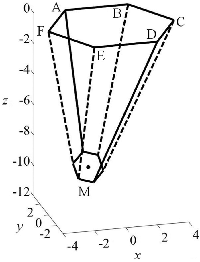
Equilibrium pose of the six-cable-driven parallel mechanisms with different cable lengths.
Example 3: irregular six-CDPMs
It is obvious that the more irregular the platform, the more difficult to converge to the global optimal point. To check the robustness of our proposed method, we tried to solve problems with this kind of challenge. In this case, the static platform and mobile platform are changed to be irregular by randomly modifying the length of
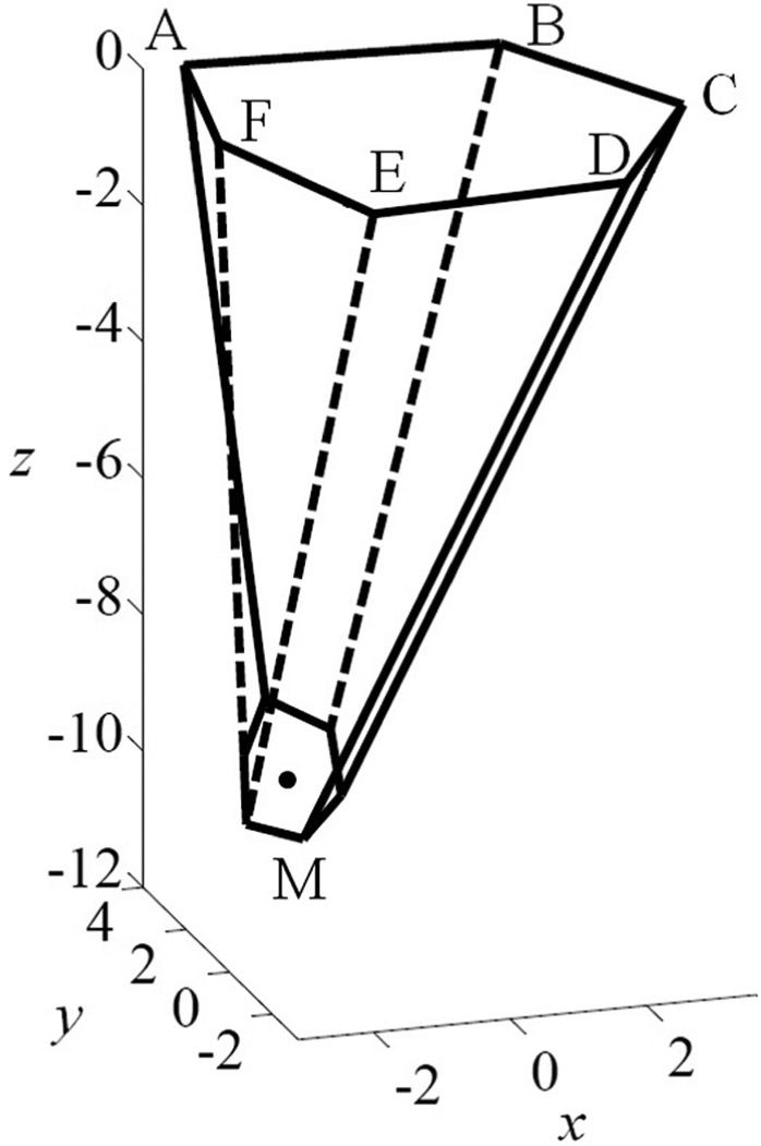
Equilibrium pose of an irregular six-cable-driven parallel mechanism.
In summary, the fully constrained problems in this section were solved by our method effectively and efficiently. We can get the same optimal results as literatures within less iteration and shorter computing time. All of these examples clearly testified the feasibility of our proposed method.
IKP of a spatial four-CDPM
An important function of FKA is error supervision, namely, contrasting the required pose with the actual pose. Usually, the IKP is solved by directly computing distances between two attachment points based on pose information. However, sometimes with the cable lengths of inverse kinematic solution, we cannot get required pose. This is an important difference between CDPM and rigid-body parallel mechanism. The phenomenon is mainly due to the cable’s feature that it can only bear positive tension forces.
To illustrate the effect of our method in supervising IKA error, a spatial four-CDPM will be analyzed. As shown in Figure 7, the static platform is a rectangle, whose length l = 120 m and width w = 80 m; the mobile platform is a square with side length s = 10 m and M is the centroid. First, several required poses will be given, based on which cable lengths are to be calculated with IKA. Second, FKA will be carried out with our proposed method on the basis of these cable lengths. Then, corresponding pose will be presented. Four of these examples are depicted in Figure 8, wherein the thin dashed lines represent the required platform configurations and corresponding cables, the thick solid lines represent the actual platform configurations and the cables with positive tension, and the thick dashed lines represent the cables with negative tensions.

Sketch of a spatial four-cable-driven parallel mechanism.

Comparison of required poses and actual poses at four configurations: (a) initial pose is [0, 0, −80, 0, 0, 0], (b) initial pose is [40, 20, −80, 0, 0, 0], (c) initial pose is [0, 0, −80, π/4, −π/4, 0], and (d) initial pose is [−40, −20, −80, π/4, −π/4, π/6].
It is not hard to see that a majority of required poses do not coincide with their actual poses; this may be due to the fact that this CDPM is under constrained. To study the influence of end-effector size s on these errors, we carried out groups of examples and obtained the following results shown in Figure 9. Evidently, there is a close relationship between s and position errors, that is, the smaller the end-effector, the smaller the position error. However, there is no clear influence for s on orientation errors. Therefore, for a spatial four-CDPM, we can control the end-effector’s position accurately if its size is relatively smaller to the static platform. To apply this mechanism in practice, the orientation errors should be compensated by adding other mechanical device, such as an A/B axis. 20

Influence of end-effector size s on position errors and orientation errors at four configurations, where |Δx|, |Δy|, |Δz|, |Δα|, |Δβ|, and |Δγ| are corresponding absolute values of the difference between the required coordinates and the actual coordinates: (a) initial pose is [0, 0, −80, 0, 0, 0], (b) initial pose is [40, 20, −80, 0, 0, 0], (c) initial pose is [0, 0, −80, π/4, −π/4, 0], and (d) initial pose is [−40, −20, −80, π/4, −π/4, π/6].
Workspace analysis of a planar four-CDPM
Workspace analysis is very important for the practical application of CDPM. Usually, workspace is calculated with the search method. 20
First, the force equilibrium equations of a CDPM at every searching point is solved and corresponding tension of cables is obtained. Then, those points which satisfy positive tension constraint will be included into workspace. However, for over constrained CDPM and under constrained CDPM, the number of variables is not equal to the number of equations. Thus, it is difficult to obtain the accurate solution of the force equilibrium equations. In this article, we propose a search-iteration method to execute workspace analysis of CDPM, which avoids solving the force equilibrium equations. Figure 10 shows the flowchart of the search-iteration scheme.

Flowchart of workspace analysis with the search-iteration scheme, where ε is the allowable error between the required pose and the actual pose, N is the iteration limit and is set to 50 here.
The core idea of the search-iteration method is to compare the difference between the required pose and the actual pose. If there is little distinction between them, then the latter one can be included into the workspace. Otherwise, the searching point will be excluded. The FKA here is carried out with the method we mentioned before, and its advantage of high computational efficiency is fully exploited. Note that we just update orientation coordinates before every new iteration and keep position coordinates as its original value. This is due to the fact that we only need to confirm that there is available orientation at the search position. If there exist available orientation coordinates at the required position, although it may not coincide with its original orientation, we can still include this position into the workspace. If we simply apply a search strategy to find the workspace, some positions actually available may be ignored due to the discretization of a search region that are always far sparser when compared with the iteration strategy. Thus, we propose to combine these two methods together to realize the workspace analysis of CDPM.
To testify the feasibility of the above-mentioned method, a planar four-CDPM shown in Figure 11(a) is analyzed. The workspace is shown in Figure 11(b), wherein arrows represent the allowable orientation range of the mobile platform at corresponding point. One single arrow means the platform just has a unique available configuration at this position. The workspace figure indicates that the freedom of the mobile platform is larger when it stays below CD than that of the mobile platform that stays between AB and CD. The feasible angle scopes of points between 8 and 12 at x axis, and between −40 and −30 at y axis at the same time, almost reach π, where region thereby can be utilized as the dexterous workspace.
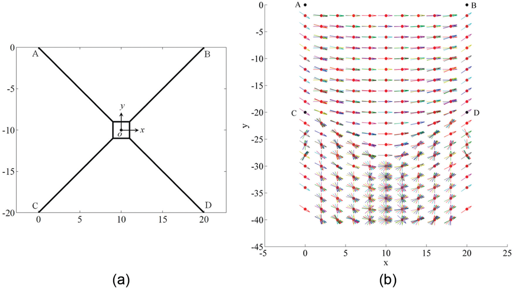
(a) Sketch of a planar four-cable-driven parallel mechanism and (b) workspace of a planar four-cable-driven parallel mechanism.
Conclusion
In this article, we proposed to conduct the FKA of CDPM with the principle of minimum potential energy. In practice, it is always the most stable pose of the end-effector that is utilized, where pose can definitely be found with our method. Therefore, the proposed method makes sense from the perspective of practical application.
After adding some constraints to design variables, the solution uniqueness of this optimization problem is guaranteed. This point is proved by an analogous strategy with a four-bar linkage. Thus, the optimization problem can be solved even with simple MP algorithms, such as SQP. Our method remarkably simplifies previous researchers’ mathematical model, which is non-convex and must be solved with a global optimization algorithm.
The efficiency, effectiveness, and robustness of our proposed method in performing FKA are validated with three spatial six-CDPMs. All resulting poses are the same with those in the literature, but the cost time is far shorter than theirs. In addition, this method is further introduced to execute the error supervision of IKP and the analysis of workspace, and it presents perfect behavior at both fields. It is worth mentioning that the examples in this article include both spatial CDPM and planar CDPM in terms of mechanism dimension, which includes over constrained CDPM, fully constrained CDPM, and under constrained CDPM in terms of constraining feature. No matter which kinds of CDPM, the idea of minimizing the end-effector’s potential energy is always available in performing kinematic analysis. This to some extent reflects the generality of the proposed method.
In further research, we should try to prove the assumption in section “Problem formulation” with more rigorous mathematical proofs, so that we can provide solid theoretical supports for the proposed method. In addition, we will validate the real-time ability of our proposed method with practical experiments, which verifies the practical value of our proposed method.
Footnotes
Academic Editor: Yong Chen
Declaration of conflicting interests
The author(s) declared no potential conflicts of interest with respect to the research, authorship, and/or publication of this article.
Funding
The author(s) disclosed receipt of the following financial support for the research, authorship, and/or publication of this article: The investigation in this paper is supported by the National Science & Technology Major Project (grant no. 2014ZX04014031), which is gratefully appreciated.