
Abstract
The 3-RRRS mechanism (RRRS refers to kinematic pairs of a branched chain consisting of three R pairs (Rotational pairs) and one S pair (Spherical pair), successively) is used between a moving platform and a static platform, through which six-dimensional motion of the moving platform relative to the static platform can be achieved. Selecting six independently drivable joints from nine active joints makes it problematic to deal analytically with the kinematics of the 3-RRRS mechanism. In this article, a novel computer-aided geometric method for kinematic analysis is developed. This method can automatically detect the independently drivable joints for arbitrary kinematic chains. This method can be easily implemented compared to the analytical method of the forward kinematics. Based on the constraint relationship of the 3-RRRS mechanism, a general 3-RRRS mechanism digital model is built in the SolidWorks Application Program Interface embedded Visual Basic environment, in which the platform sizes and active driving angles are driven by the parameterized model, to make the moving platform move to the corresponding pose. After the pose of the moving platform is confirmed, the coordinate system is built in a preliminary sketch. The parameters are measured by the SolidWorks measuring functions, and the pose of the moving platform is obtained by combining homogeneous matrices. Using the computer-aided geometric method, the detailed kinematics formula is not required. The accuracy and efficiency of the computer-aided geometric method were assessed with some examples of kinematic analysis for the 3-RRRS mechanism. The results showed that the proposed method obtained competitive precision and calculation time to the analytical method and is beneficial as a convenient solving process. By using Visual Basic programming, a reachable poses analysis of the mechanism can be merged into the kinematics analysis system of the computer-aided geometric method. The computer-aided geometric method could be widely applied to kinematics analysis of mechanisms.
Keywords
Introduction
To achieve variations of a pose between the platforms above them, several studies have been carried out on the movement of branched chains connecting the moving and static platform. Regarding branched chains, for example, Hunt 1 proposed a 3-RPS mechanism (RPS refers to kinematic pairs of a branched chain being a R (Rotational pair) pair, P pair (Prismatic pair), and S pair (Spherical pair), successively) to realize two rotations and a translation. Fang et al. 2 studied the differential kinematics problem of a 3-RPS parallel mechanism and analyzed the instantaneous motion characteristics of the parallel mechanisms, such as 3-RPS and 3-RRS. Based on the symmetric structure of 3-RSR parallel robot, Fang et al. 3 studied a position display analytical solution of a three degrees of freedom (DOF) mechanism. Luo et al. 4 studied a 3-SRR/SRU (SRU refers to kinematic pairs of a branched chain being an S pair, R pair, and U pair (Hooke pair), successively) 3-DOF coupling parallel mechanism. Research on the Stewart parallel mechanism is a very typical and in-depth method to form a mechanism with branched chains. 5 In our research, to form the 6-DOF motion of the moving platform, a new 3-RRRS branched chain connecting a moving platform and a static platform is proposed, which has the characteristics of a redundant drive.
When the mobility of the mechanism is increased up to the required DOFs of the moving platform, the manipulator is a kinematically redundant parallel manipulator. 6,7 On the other hand, a parallel manipulator is a redundantly actuated manipulator when the number of actuators is greater than the mobility of the mechanism. 8,9 In general, it is believed that the redundancy can usually improve the ability and performance of the parallel manipulator, for example, by avoiding kinematic singularities, increasing workspace, improving dexterity, and increasing load capability. 6 –9 Lee et al. 10 presented a novel energy-saving method of a robotic system using a parallel mechanism by redundant actuation that can reduce the peak torque of the actuating joints. Shin et al. 11 investigated how to remove parallel singularities through redundant actuation. Moreover, it has been reported that a redundant parallel manipulator has a better rigid dynamic performance than that of its nonredundant counterpart. 12
Research on the 3-RRRS mechanism has proven that it is very difficult to select six independently drivable joints from nine active joints in the forward kinematics analysis as the other parallel robot mechanism because forward kinematics analysis on the 3-RRRS mechanism may lead to a univariate 16th order polynomial equation that is difficult to solve.
Forward kinematics analysis of the parallel robot mechanism is very typical on a Stewart platform. Various studies 13 –15 have suggested that forward kinematics analysis on a Stewart platform eventually causes a univariate 16th order polynomial equation to solve. To solve the direct kinematics of a 3-RS parallel mechanism, Kim et al. 16 used Sylvester’s dialytic elimination method; the direct kinematic problem is simplified to the solution of a 16th order polynomial equation with a single variable.
Deducing the univariate 16th order polynomial equation is rather complex, requiring both the variable substitution and the Bezout method, and thus efficiently solving such a high order polynomial equation is even more challenging. Ku 17 proposed a numerical iterative algorithm based on the Newton–Raphson method for the position positive solution of the 6-3 type Stewart platform mechanism. Song et al. 18 analyzed three kinds of common methods for position positive solutions on the Stewart platform based on the polynomial method, the numerical iterative method, and the additional sensors method. 19
Since the solving procedure involves a complex computer program, the requirements of parallel mechanism real-time control are difficult to meet, and finding the solution is highly time-consuming. Therefore, finding better forward solutions for the parallel mechanism remains an ongoing challenge up to now.
For the kinematics analysis of the 3-RRRS mechanism, the most commonly used method to solve robot kinematics is based on the Denavit–Hartenberg notation. Yu et al. 20 proposed an effective approach to solve the inverse displacement analysis for a class of modular three-legged parallel robots by Paden–Kahan subproblems. Liu et al. 21 discussed the forward and inverse displacement analyses of the 3/3-RRRS parallel manipulator, a novel geometrical method referred as equivalent mechanism was proposed for the forward displacement analysis of the manipulator. Derived from the basis of screw theory, Goutham et al. 22 studied a new improved inverse kinematic approach for a 6-DOF 3-RRRS parallel manipulator. Along with Paden–Kahan subproblems, a new and improved subproblem is used.
We proposed a novel dimensionality-reduction method to improve forward kinematic analysis of a reptile-like four-legged walking robot with 4-RRR motion chain. 23 For the reptile-like four-legged walking robot, the basis of forward kinematics analysis and solving workspace of the robot was acquisition of the subordinate driving angles. For solving these angles, a set of 16 nonlinear equations was obtained by Professor Chen Xuedong 24 after complex deductions in the analysis of forward kinematics of the robot. Abel theorem shows that quintic equations of higher order have no general algebraic method of obtaining solutions and that they can be solved only by numerical method. As the robot uses redundant drives, forward kinematics analysis using analytical method is difficult. 24 We proposed a computer-aided geometric (CAG) method for forward kinematics analysis of the robot to solving the stable workspace of quadruped bionic robot with hand–foot-integrated function. 25,26
In our further research, we recognized that the forward kinematics analysis of the 3-RRRS mechanism needs the completed derivation of the kinematics equations. Solving the equations of motion is very complicated; however, using computer software to model the mechanism is a very effective way to simplify the task.
For a configuration of the reptile-like four-legged walking robot, a motion branch chain of each leg is a RRR open chain, which is not quite the same as the 3-RRRS mechanism. When using a CAG method for forward kinematics analysis of the reptile-like four-legged walking robot, we have not considered a motion range of each branched chain, especially, the motion range and position change of S pair. The other problems, such as the forward kinematic analysis of the velocity and acceleration, singular (or special) configuration of the mechanism, have not been studied, also. We need to further improve and systematize the previous work to developing a CAG method to analyze the motion of the 3-RRRS mechanism. 25,26
Developing a CAG method to analyze the motion of the mechanism for reducing the difficulty of the analysis process and reducing the solving time is our research goal.
Many scholars have researched robot movement analysis using geometric methods. For example, Lin et al. 27 adopted a geometric method mixed with an analytical method algorithm to solve the inverse kinematics of a modular manipulator robot with shoulder offset. Yang et al. 28 presented a geometric method for solving the inverse and forward kinematics of a Delta robot. The forward kinematics are simplified as solving the intersection point of two circles and then transforming the coordinates system to obtain the final solution.
The geometric method is also used in the study of redundant drive mechanisms. Shim et al. 29 proposed a novel optimal torque distribution method for a redundantly actuated 3-RRR parallel robot using a geometric approach, and a geometric analysis based on screw theory was carried out to calculate the stiffness matrix of the 3-RRR parallel robot.
In most instances, the geometric method has been used as an auxiliary method in the analysis of the mechanism motion. Using the CAG method, which establishes a three-dimensional digital driven mechanism model and combines with a variety of software technologies, the mechanism motion pose is not directly involved.
In this article, a CAG method for analyzing the 3-RRRS mechanism is developed. Based on the constraint relationship of the mechanism, a SolidWorks digital model of the mechanism is established, and a general digital model of the 3-RRRS mechanism is formed by using the SolidWorks program from the Visual Basic (VB) environment. The main innovative points include: By using the digital model, the platform sizes and independently driving angles are driven by a parameterized model. The parameterized model can automatically detect other drivable joint angles for arbitrary kinematic chains to make the moving platform move according to the corresponding pose. The parameters are automatically measured with the measure functions in SolidWorks. The pose of the moving platform is obtained by combining homogeneous matrices, and the forward kinematics of the mechanism can be solved. The CAG method makes it so that the detailed kinematics formula is not needed, which provides a heuristic thought for motion analysis of the mechanism. By using VB programming, a velocity analysis, an acceleration analysis, a singularity analysis, and a reachable poses analysis of the mechanism can be merged into the kinematics analysis system of the CAG method. These can greatly facilitate the characteristics analysis of the mechanism.
This article is organized as follows: In the second section, the configuration of the 3-RRRS mechanism is described. In the third section, the difficulty of the analytical method of forward kinematics for the 3-RRRS mechanism is reviewed, and the CAG method is proposed in the fourth section. In the fifth section, some examples of the analysis are presented. Some issues about the velocity and acceleration analysis, the singularity of the mechanism, and the application of the CAG method in a real system are discussed in the sixth section. Conclusions are drawn in the seventh section.
The configuration of a 3-RRRS mechanism and its application
A configuration schematic diagram of a 3-RRRS mechanism connecting the moving platform and the static platform is shown in Figure 1. The motion axis of the R pair, which connects to the moving platform, is vertical to the moving platform. The motion axes of the two R pairs in the middle are parallel to the moving platform. An S pair of the RRRS branched chain is connected to the static platform. Each R pair of the three branched chains has a drive motor. The moving platform can form six-dimensional movement. Due to the 6-DOFs of the moving platform, nine driving pairs in the three branched chains exist, and only six of these pairs are independently driving pairs.
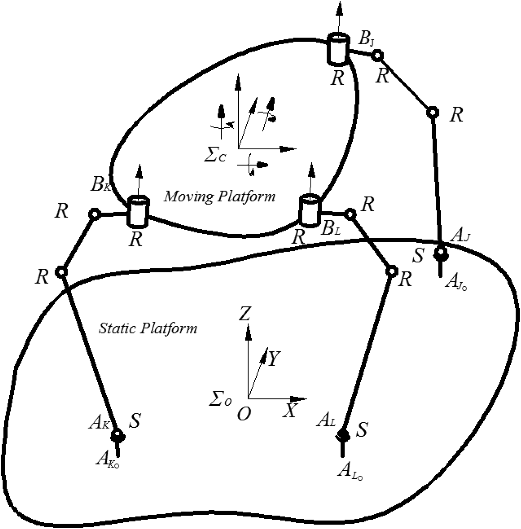
A configuration schematic diagram of a 3-RRRS mechanism.
Applications of the 3-RRRS mechanism are very extensive. For example, if remove the elements contacting the static platform from the S pairs, the S balls of the S pairs will contact the static platform directly. Another RRRS branched chain is added to connect the moving platform, and the moving platform is transferred as a body installing controllers, and thus a typical configuration of the reptile-like quadruped robot can be formed.
Yu proposed that there are two kinds of configurations for three-legged parallel robots. One is 3-RRRS type whose active joints are all revolute joints, another one is 3-RPRS type whose active joints include both revolute and prismatic joints. 20 Yang et al. 30 researched a self-calibrated three-legged (6-DOF, RRRS) parallel robot. Yu et al. 31 designed a bionic robot, by 3/3-RRRS parallel mechanism driving teeth up and down, which achieved full chewing of food to study a masticatory movement of mankind for food processing.
The forward kinematics of the mechanism need complex derivation of the kinematic equations and six independently drivable joints are selected from nine active joints. Solving the kinematic equations is very complicated. A deeper understanding of kinematics analysis is of universal significance.
The difficulty of the analytical method of forward kinematics for a 3-RRRS mechanism
A kinematic sketch of a 3-RRRS mechanism is shown in Figure 2. The connection points between the S pair and the static platform are

A kinematic sketch of the 3-RRRS mechanism.
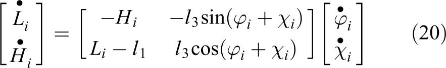
The distance between the sphere center of the S pairs and the static platform is hL
, and it is the same and perpendicular to the static platform in the three branched chains. The link lengths of each branched chain (from top to bottom) are l1
, l2
, and l3
, respectively.
Because the points


where
A schematic of part of the three branched chains (from Ai
to Bi
(i = J, K, L)) is shown in Figure 3. The variables A schematic of part of the three branched chains.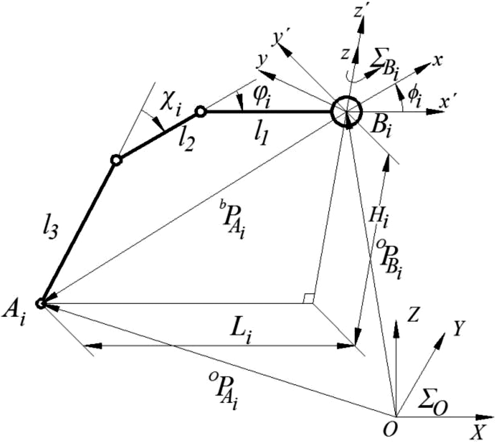

The projection of 3-RRRS mechanism in the x–y plane of


The projection of the mechanism in x–y plane of
where i = J, K, L.
Because the distance between the centers of the sphere of the S pair are the same in both

where (i = J, K, L), (j = J, K, L, and i ≠ j),
The moving platform has six DOFs. In total, nine driving joints in three branched chains exist, and only six of the joints can be independent driving joints; the remaining are subordinate driving joints. Without any loss of generality, it can be assumed that the joint variables
By substituting equations (3) and (4) into equation (5), the following equations can be obtained

Using equation (6), we obtain

where ai , bi , and ci are functions of known variables and they are expressed as follows


For solving the variables of the subordinate driving joints in equation (7), let
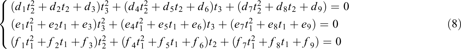
where di
, ei
, and fi
are functions of the known variables. Their detailed expressions are expressed as follows:
At this step, variables t 2 and t 3 can be eliminated from equation (8) using the Bezout method. The final equation only has the variable t 1, which is expressed as follows

where vi (i =1, 2,…, 17) are the coefficients which are functions of the known variables, and their specific expression are omitted here. It should be noted that the solving process and the coefficients are very complicated. Equation (9) is a 16th order equation, and according to Abel’s theorem, there exists no universal algebraic solution for this equation. Only numerical solutions for fifth order or higher polynomial equations exist. In other words, solving the equation of the 3-RRRS mechanism is challenging in practice.
As stated in the first section, many methods have shortcomings for solving this kind of equation, and the computational efficiency of many methods is very low. Sometimes, for a 16th order equation, only 16 imaginary roots can be obtained with a longer calculation time, and there is no real solution. A goal of this study is developing a novel method for solving this kind of problem. After using a relevant method to obtain the subordinate driving variables
where (i = J, K, L), (j = J, K, L), and i ≠ j.
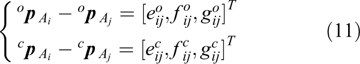
where (i = J, K, L), (j= J, K, L), and i ≠ j.

Considering the features of the standard orthogonal matrix
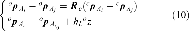
Then, the moving platform’s trajectory (shown by the motion locus of origin C in

By substituting equation (10) into equation (13), we obtain

where
Note that the solving of equation (9) using the analytical method is cumbersome. A CAG method for the mechanism kinematics is proposed below.
A CAG method of 3-RRRS mechanism kinematics
In a kinematic analysis system based on the CAG method, a VB program was used to join the SolidWorks system for constructing a 3D parameterized model of the mechanism. Different parameters of the mechanism were input using the VB program to drive the model to change its dimension, position, and posture in SolidWorks.
Using the CAG method for mechanism kinematic analysis, the parameterization technology is used .The parameterization technology means that a model size of the mechanism will automatically change when a user input different the mechanism parameter. That is, if a user changes a parameter, the system can update the mechanism’s geometry model automatically and configuration to maintain consistency of the model.
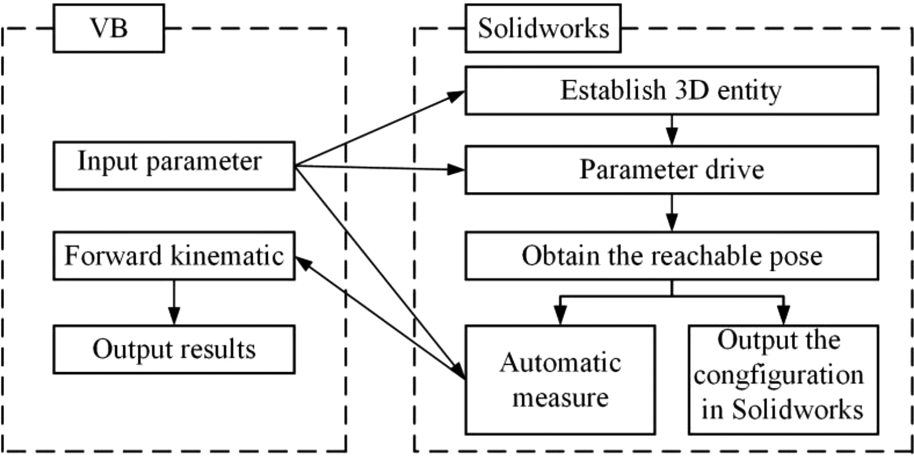
The flow chart for the kinematics analysis of the mechanism is shown in Figure 5. The independently driven angle was driven by this parameterized model to make the moving platform move to the corresponding pose. After the pose of the moving platform was confirmed, the coordinate system was built in a preliminary sketch. The parameters were automatically measured using SolidWorks functions, and the pose of the moving platform was obtained by combining homogeneous matrices; the reachable poses of the platform can be shown in SolidWorks if need be. The kinematics analysis of the mechanism was then achieved.

The CAG method flow chart. CAG: computer-aided geometric.
Principle of the CAG method
Achieving the passive drive of the incompletely constrained components in SolidWorks is important for developing and applying a digital model of the mechanism. In the assembly of SolidWorks, except for the fixed part, each active part has six DOFs, and the number of DOFs of the parts is reduced as the constraints increase. When part A increases with the cooperative relationship to change its position or posture, part B, which has constraint relationship with part A, also passively changes its position and posture with the new increased cooperative relationship. However, if part B has been fully constrained, then no matter how it moves to a position or lays out in whatever kind of posture that cannot meet the new increased cooperative relationship, then the SolidWorks system shows a warning. In addition, the relationship between the original position and posture of the part remains unchanged in the whole system.
In our 3-RRRS mechanism’s analysis system, developed by the VB program driving SolidWorks software, a 3D model of each part is established. Based on the theoretical model of the 3-RRRS mechanism, the 3D model of the mechanism is assembled in the assembly file. At this time, the assembly model of the mechanism only has a basic cooperative relationship, that is, the motion of the kinematic pairs, including the R pair and S pair, of each module is a pure rotation. For the whole mechanism model, it has six DOFs, and the most basic constraint relationship is formed on the structure. After structural constraints establish the independently driven angles and the positions of the spherical pair S, all six DOFs of the mechanism model are subject to constraints.
For the 3-RRRS mechanism, the structural parameters of the mechanism model include the length 2m and the width 2n of the moving platform; the link lengths l1
, l2
, and l3
of the branched chains; and the height hL
and positions
The digital model of the overall mechanism structure is formed. Without a loss of generality, suppose the rotation angles
The technology of the application software
In the developed kinematic analysis system, the data access between the VB environment and SolidWorks can be visualized as shown in Figure 6.
The application software.
The API function feature of SolidWorks
The modeling process mainly adopts design features of a 3-D entity model based on the characteristic parameters and an assembly model based on constraints in SolidWorks. This software has hundreds of Application Program Interface (API) functions that are Object Linking and Embedding for SolidWorks or a Component Object Model (COM) Interface, which support a Windows application program to operate other Windows procedures by acquiring object control. In this design, the API functions are used to develop the program. In the API help manual, SolidWorks provides API objects at all levels as well as the parent–child relationships.
When using an API function, before controlling a sub_object, the control right of its father_object must first be taken; a control right of each sub_object belongs to its father_object. Each object has its specific functions or attributes. Most of the functions of normal operation in SolidWorks are encapsulated in the object at all levels. Programmers who gain the control right of the object can modify the attributes of the object or perform its function to realize the basic process.
Using the VB environment to call the API function
In the application of the mechanism modeling, the VB environment and Windows application program are used to build an interface for calling the SolidWorks API function and developing the required functionality.
Detailed technology of CAG method
Establishing a 3-D model of the 3-RRRS
According to the theoretical model of the 3-RRRS, the 3-D model is first established and it is mated in SolidWorks. Figure 7 depicts an assembly with the basic cooperating relationship. During assembly, the position of a spherical pair is set on the ground; the center of the ground coincides with the center of the assembly, and each reference plane coincides between the ground and the assembly.

A 3-D assembly model of the 3-RRRS mechanism.
A fixed coordinate system is set as the acquiesced coordinate system of the assembly. At this step, positions of the spherical pairs in the fixed coordinate system and in the acquiesced coordinate system of assembly coincide. The position control for the spherical pair controls the distance between the point and each reference plane in the acquiesced coordinate system of the assembly, which belongs to a cooperative control of distance type.
Positions
The parameterization of the parts
Parts parameterization means automatically changing part models size following the different input parameters.
To establish the universal digital model of the3-RRRS mechanism, the length of the mechanism’s link; the sizes of the moving platform; and the positions
If the sizes of the moving platform and positions
For the system developed in this article, first, a suitable range of the moving platform size and points
Stretching the length is used to control each link’s size of the mechanism model when using parameterization technology to drive the length of a link. In achieving parameterization of parts, the SolidWorks API function is needed. First, it is necessary to obtain control rights for the superior object of the function. There are two methods for acquiring the control rights of the highest level object of API function in SolidWorks (i.e. the control rights of SolidWorks). For a more detailed method, see the SolidWorks user’s guide. 32 After gaining the control rights of the highest level application object, the controlled object can be opened and handled. In the design, it is the 3-D assembly of a theoretical model of the 3-RRRS mechanism.
In the system built using the CAG method, the draft dimension or characteristic dimension are driven to realize the parts’ parameterization. Details about realizing parts’ parameterization are given in Appendix 2.
A certain cooperative relationship of the structure should be controlled whether the mechanism model is formed and the sizes are confirmed or not. It is very important for the CAG method to successfully control the cooperative relationships of the mechanism’s independent driving angles and the cooperative relationship of the spherical pair’s position.
The key functions of adding a cooperative relationship in SolidWorks are used to control the cooperative relationship of the defined components. Details regarding adding a cooperative relationship are discussed in Appendix 3.
When the programs are used to control the position of the spherical pair and the independently driven angles, the sequence of the drive should be considered. In the forward kinematic analysis, the independently driven angles are coopted first, and then the spherical pair’s positions are coopted. On the contrary, assembly errors are prone to occur.
All coordinate relations between components in the mechanism model are the angle component and distance coordination.
Using the VB program to input parameters
The parameters of the variable are input using the VB program after the digital mechanism model is set by secondary development of Solid Works. Figure 8 shows the interface of the forward kinematics system of the mechanism using the VB program to input the parameters.
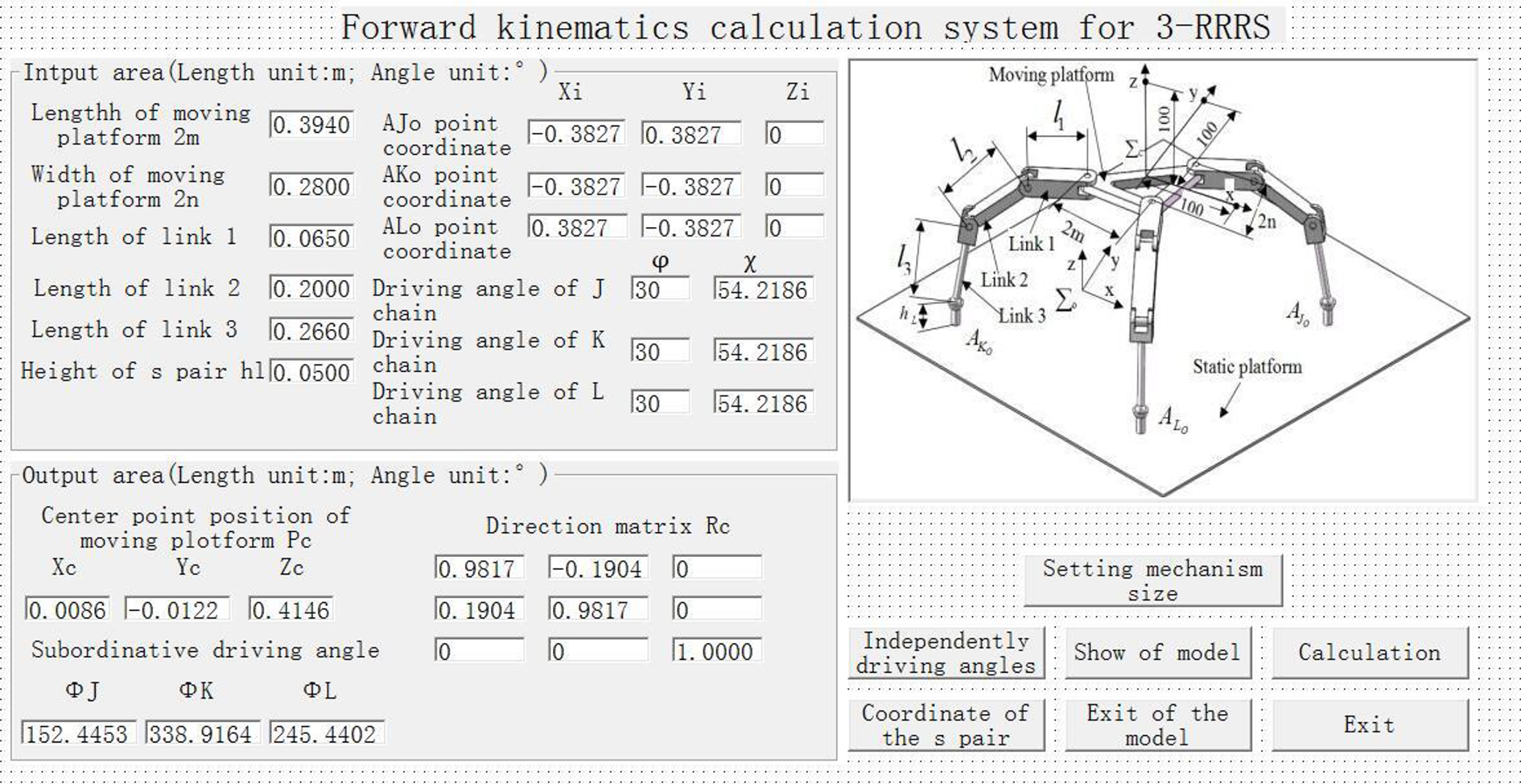
The interface of the forward kinematics system of the mechanism for Example A.
Driving the 3-D assembly model of the 3-RRRS mechanism
Dimensions and positions of the components change along with the different input value by using the VB program to call the digital model of the mechanism. The adoption of the corresponding method confirms the mechanism model’s six independently driven angles and the three fixed positions of the spherical pair. The assembly of the mechanism model can form the position and the pose of the moving platform which matches the given conditions.
Measurement of the related parameters
When the mechanism model moves to the specified pose under the SolidWorks’ drive, the mechanism kinematics relationship is formed with a specified cooperation relationship. The related parameters are measured, and results are obtained as output.
In the proposed analysis system, the internal measurement system in SolidWorks is used. In Figure 7, the default coordinate system in SolidWorks is set as a fixed coordinate system. The reference coordinate systems are set in the center point C of the moving platform. Specific implementation processes are given below.
Using SolidWorks, a “static platform” part is inserted in the mechanism’s assembly. The default coordinate system of the “static platform” part and the mechanism’s assembly are set to coincide by the cooperative relationship of the assembly so that the “static platform” part is fixed. The center of the “static platform” in a default coordinate system is the geometric center. In measurements, the default datum plane in the “static platform” is used as a reference, and the vertical distances from points to each datum plane are measured. These are the coordinate values of the points in the fixed coordinate system.
The floating coordinate systems (i.e. coordinate system
Assume that
Calculation of the mechanism’s pose
The vector expressions of the floating coordinate system in the fixed coordinate system are

In equation (15)

The physical meaning of equation (15) is shown in Figure 9.
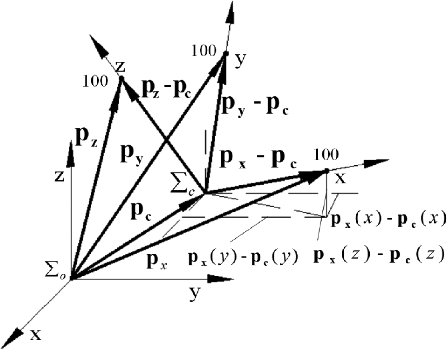
The physical meaning of equation (15).
Equation (15) can be changed as follows

Vector P has a transformation relationship between the coordinate system

From equation (17), we have

Let
Obviously, using the CAG method eliminates a complicated formula derivation, and obtains the same results as using the analytical method.
Using the SolidWorks API functions to measure position coordinates of the relevant points, each element of
The development of the computing system
Based on the above ideas, after the mechanism’s digital model is established, the sizes of the links and the moving platform, and the spherical pair’s positions can be changed and controlled. The cooperative relationship in the mechanism model is controlled based on the mechanism’s independent driving angles and the position of the static platform, which makes the mechanism model form the posture and position under all restrictions. Because the VB program automatically calls the SolidWorks measure function to measure the position of points and calculates the homogeneous coordinate matrix of the two coordinate systems, the posture of the moving platform is obtained. The forward kinematics solution of the mechanism can be obtained by the output functions of the VB program. Figure 8 shows the interface of the VB program of the developed forward kinematics system.
Calculation examples and discussion
Example A
The structure and motion parameters are as follows (see Figure 2):
Calculation using the analytical method
From equation (10), we have:
As shown in Figure 2, we can obtain

According to equation (2), we have:
According to equation (3), we have
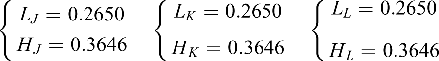
Using the above results and equation (4) yields

Using the above results yields the equations the same as in equation (6).We obtain the equations the same as in equation (7). Considering the structure of the mechanism, the motion ranges are given for
Example A: The subordinate driving variables.

The function ‘fsolve’ in MATLAB can be used to solve the equations the same as in equation (7).
33
Subordinate driving variables
Calculation using the CAG method
Using the VB program to input the parameters into the system, the interface is shown in Figure 8 and the output calculation results are shown in Figure 8

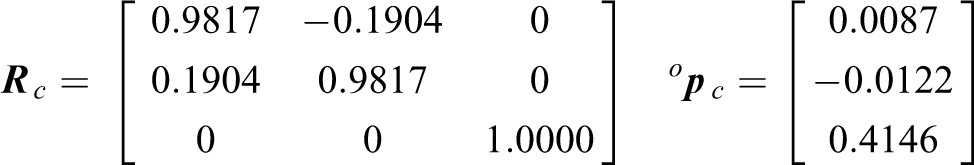
Example B
The structure and motion parameters are as follows (see Figure 2):
Calculation using the analytical method
The details of this example are omitted here since it is like Example A. The outputs of the subordinate driving variables are summarized in Table 2.
Example B: The subordinate driving variables.

The final calculation results are

Calculation using the CAG method
Using the VB program to input the parameters into the system, the interface and the calculation results are shown in Figure 10.

The interface of the forward kinematics system of the mechanism for Example B.
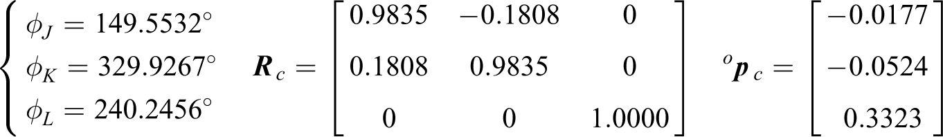
Example C
The structure and motion parameters are (see Figure 2):
Calculation using the analytical method
Since this example is similar to Example A, the details are omitted here. The outputs of subordinate driving variables are summarized in Table 3.
Example C: The subordinate driving variables.

The final calculation results are
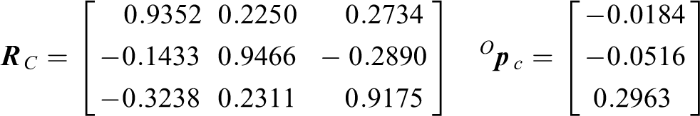
Calculation using the CAG method
Using VB program to input the parameters into the system, the interface and the calculation results are shown in Figure 11
The interface of forward kinematics system of mechanism for Example C.

The reachable poses of the platform can be shown in SolidWorks if need be. Here, we output the reachable poses of the platform for Example C using the output button “Show of model” in the interface of forward kinematics system of mechanism, shown as Figure 12.

The reachable poses of the platform for Example C.
Discussion
To compare the accuracy of both methods, equation (7) can be rewritten as follows

The calculated values of the variables
Table 4 compares the results of the two methods for Examples A, B, and C, through which the precision of the mechanism motion obtained by the CAG method is not lower than that of the analytical method. The reason for this is that the calculation using the analytical method requires multiple mathematical transformations and data transfers of the intermediate variable while calculation using the CAG method is concise and visual. Table 4 shows the calculation times are observably less when using CAG method than using analytical method, which is very meaningful for meeting the requirements of the mechanism real-time control.
Comparison between the calculation precisions and calculation times of the two methods.

Discussions on relevant issues
In this section, some issues about the analysis of the velocity and acceleration, the singularity of the mechanism, and the application of the CAG method in a real system are discussed.
Forward kinematic analysis of the velocity and acceleration of the 3-RRRS mechanism
Forward kinematic analysis of the velocity and acceleration of the 3-RRRS mechanism is to determine the motion velocity and acceleration of the moving platform, based on analyzing the position and attitude of the mechanisms and giving the velocity and acceleration of independent driving joint. The proposed forward kinematic analysis of a 3-RRRS mechanism using a CAG method is focused on solving the complex derivation of the kinematics equation and the solving process in the pose analysis. In the forward kinematic analysis of the velocity and acceleration of the 3-RRRS mechanisms, the relevant expressions of the velocity and acceleration analysis need to be deduced. The obtained joint variables using the CAG method are substituted into the velocity and acceleration analysis equations of the mechanism, and then the velocity and acceleration of the moving platform are solved. Here, the velocity analysis of the moving platform is used as an example, and the relevant expressions are given.
The velocity analysis of the moving platform is to determine
The velocities of the subordinate driving joints can be obtained by differentiating with respect to time for equation (6), and then we have

where


According to the joint variables of the three branched chains, it is easy to solve
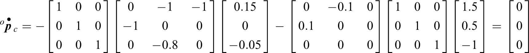
Firstly, by differentiating with respect to time for equation (10) and considering

Differentiating with respect to time for equations (3) and (4), then they can be combined to obtain


Then according to the basic definition of velocity, we have

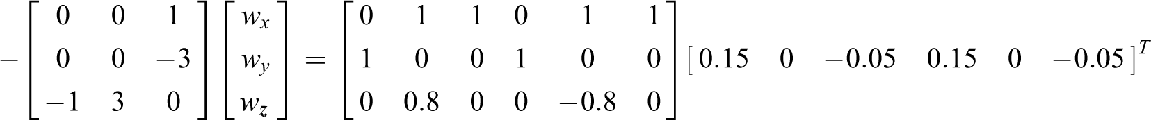
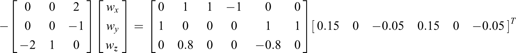
By using equations (22) to (25), let


The above equation can be determined according to the position and pose solutions obtained previously. Equation (26) can be rewritten and we have
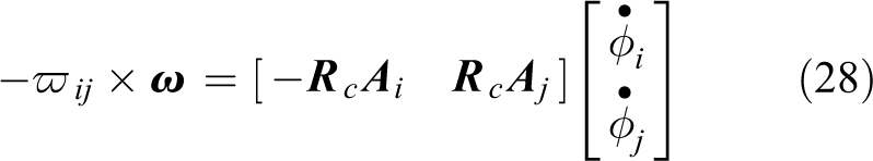
The following antisymmetric matrices are established:

Therefore, equation (28) can be rewritten as follows

If

It should be noted that if
Then, differentiating with respect to time for equation (13), we have

Similarly, the following equation is easy to obtain

Thus far, using equations (31) and (33),
The derivation process of acceleration expression for the moving platform is like that of the velocity. The specific expressions are omitted here.
By using VB programming, these calculation equations and the solving process can be merged into the kinematics system of the mechanism, as shown in Figure 8. More specific research will be conducted in our future work.
Here, we use a computational example to illustrate the problem how to construct a full rank matrix to solve
The structure and motion parameters are (see Figure 2):
From equation (10), we have:
As shown in Figure 2, we can obtain

According to equation (2), we have:
According to equation (3), we have

Using the above results and equation (4), yields

Using the CAG method, yields
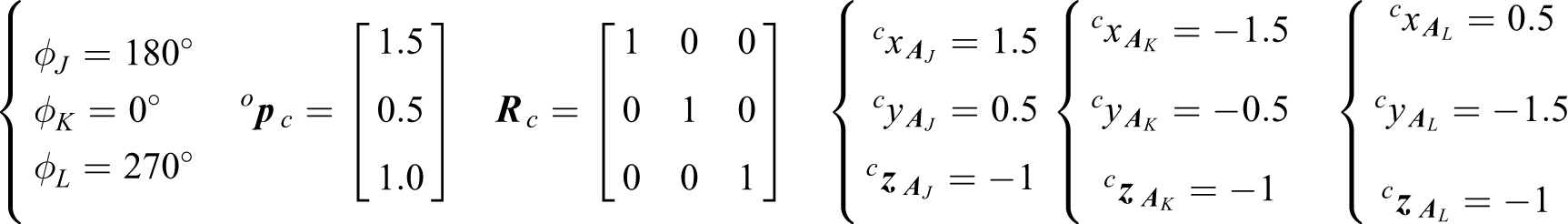
According to equations (20) and (21), we can get
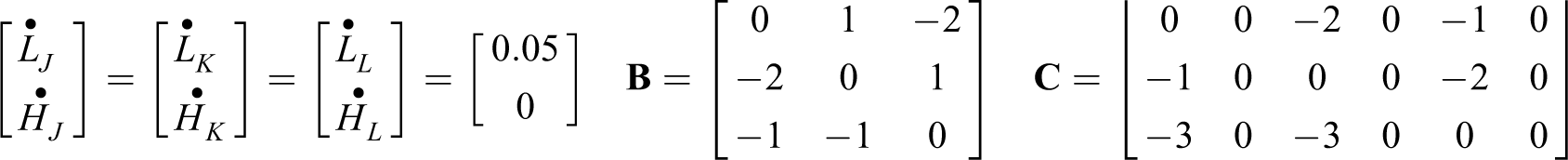
Then from
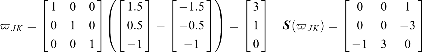
Since

According to equation (24), we can obtain

Therefore, according to equation (30), when i = J, i = K, and i = J, i = L, we can get
Using the above results, yields:
Namely, wx
= 0, wy
= 0, wz
= 0.1 (unit: rad/s),
Accordingly, when i = J, the following results can be obtained from equation (33). (unit: rad/s)
Singularity analysis
Singular (or special) configuration is a complex problem in the study of a closed-loop mechanism, especially a parallel mechanism. For a long time, there have been many scholars that have given much attention to the study of singular configuration. 34
Singularities can be divided into three forms: boundary singularity, local singularity, and structural singularity. Singular configuration is an inherent property of a mechanism, which has a serious impact on the working performance of the mechanism. When the mechanism is in a specific configuration, its velocity Jacobian matrix is a singular matrix, that is to say, the determinant value of the velocity Jacobian matrix is zero, infinite, or uncertain. At this time, the configuration of the mechanism is called the singular configuration. Boundary singularity: When the determinant value of the velocity Jacobian matrix is equal to zero, then the mechanism is in the boundary singular configuration. Local singularity: When the determinant of the velocity Jacobian matrix tends to be infinite, then the mechanism is in a local singular configuration. The local singularity means that there is an uncontrollable DOF at the end of the mechanism. Structural singularity: When the determinant of the velocity Jacobian matrix tends to be zero, then the mechanism is in a structural singular configuration. The structural singularity is also a unique characteristic of the parallel mechanisms. Only when the special sizes of the mechanisms are satisfied can the structural singularity be generated.
For this study, a CAG method is used to analyze the motion of the mechanism. When the structure and motion parameters of the mechanism are input, then the forward kinematics system could automatically form and display the real-time structure of the mechanism. It is more convenient for researchers to judge the singular configuration of the mechanism and improve the structural and motion parameters of the mechanism in the design and control of the mechanism by calculating and analyzing the determinant value of the velocity Jacobian matrix and observing the real-time configuration of the mechanism.
Specifically, the determinant values for the coefficient matrix If the determinant value of the left coefficient matrix If the determinant value of the left coefficient matrix If the determinant values of the left coefficient matrix
By using VB programming, these criteria can be merged into the kinematics system of the mechanism, as shown in Figure 8. The system can automatically prompt and display the real-time configuration of the mechanism when the mechanism configurations meet the above conditions. Researchers can observe and judge the singularity configurations of the mechanism more intuitively.
More systematic and specific research on this will be conducted in our follow-up work.
The implementation of the proposed method in a real system
When the structure of each component of the mechanism is determined and assembled for a real structure of the 3-RRRS mechanism, then the structural parameters of each component are determined. After the three branched chains are connected to the static platform, the coordinates of the connection points in a global reference
As a specific application for the 3-RRRS mechanism (the kinematic sketch is shown as Figure 2), let hL = 0. That is, removing the elements contacting the static platform from the S pairs, the S balls of the S pairs will contact the static platform directly, another branched chain is added, and the moving platform is transferred as body installing controllers; the reptile-like, quadruped MiniQuad-I robot was developed by Huazhong University of Science and Technology. Figure 13 shows the structure.

The structure of the MiniQuad-Irobot.
Conclusions
This article presented a 3-RRRS mechanism with subordinate drive characteristics. A CAG method was developed for the kinematics analysis of this mechanism. Based on the CAG method, the forward kinematics system of the mechanism was implemented by using a VB program to make a secondary development of SolidWorks. When using the proposed method for kinematics analysis of the mechanism, the detailed derivation of the kinematics formulas is not required. Only the constraint relationships of the mechanism should be explicit, and the active and passive constraints should be determined. When the mechanism’s digital model is established and the cooperated relations are considered, then the position and posture of the mechanism can be expressed clearly by the proposed forward kinematics calculation system for the 3-RRRS mechanism. The logic of this method could be widely applied to the motion analysis of mechanisms with subordinate drives, and when using the analytical method, it overcomes the difficulty in the forward kinematics.
Footnotes
Declaration of conflicting interests
The author(s) declared no potential conflicts of interest with respect to the research, authorship, and/or publication of this article.
Funding
The author(s) disclosed receipt of the following financial support for the research, authorship, and/or publication of this article: This work is supported by the Key Science and Technology Research Project of the Henan Province (182102210159), China, and Doctoral Research Funded Projects of Zhengzhou University of Light Industry (2016BSJJ009).