
Abstract
According to the energy consumption characteristics of hydraulic actuator, the valuable foot trajectory characterized by using segmented cubic spline interpolation curve in the swing phase is proposed firstly to reduce the energy consumption of quadruped robots, which is implemented by using controlling parameters tf to change the duration of leg raising and falling in one gait cycle, and then realized the directly control to the time ratio between the piston extension and retraction. Then, the total energy consumption of the hydraulic actuated quadruped robot SCalf-II is modeled. Meanwhile, the parameters of the foot trajectory that have a large impact on the energy consumption are determined. Finally, simulation analysis and verification experiments of the robot moving with constant speeds at the key parameters are performed. The results show that for the given foot trajectory, the optimization ranges of the gait cycle and duration of leg lifting from the lowest to highest are determined in which the energy required for the robot locomotion is at a relatively low level.
Introduction
Energy efficiency is an important index that has attracted increasingly more attention in modern engineering, and the development of quadruped robots is no exception. As a legged robot that is relatively simple in terms of structure and control algorithms, 1,2 the quadruped robot has become an object of more focus. Currently, however, energy efficiency is still the main bottleneck restricting its development. 3 By comparison with Cheetah, the electrical driven quadruped robot designed by MIT, the COT (Cost of transport) of BigDog, the hydraulically driven quadruped robot, is up to 15, which is near to 30 times of the former.
To improve the energy efficiency of a quadruped robot, many methods have been proposed by numerous researches. The most direct and effective way is the passive dynamic walking. The robot with this feature 4,5 does not depend on any energy input or active control and can realize walking on a shallow slope only with the movement inertia of components. Although with high energy efficiency, the passive dynamic walking do not have motion flexibility terrain adaptability, what greatly limits its application. Another efficient method for improving energy efficiency is using the elastic elements, such as the series elastic actuator 6,7 and variable stiffness actuator, 8,9 the driving devices that directly locates some elastic devices between the load and the output terminal of the actuator. Through direct force control or active impedance control, these actuators not only can reduce the consumed energy against angular inertia but also can improve contact compliance between the ground and robot feet and reduce energy consumption during contact impact. 10,11 However, the quadruped robot actuated by these actuators also has adaptability limitation to a certain extent because of their structure, mechanical properties of the material or the difficulty in component design, especially for the robot actuated by the actuator with straight movement.
The motion optimization, which do not rely on elastomers, is another effective method in improving the robot’s energy efficiency. Yang et al. 12 propound a practical foot trajectory planning method that uses the Fourier series to express the position, velocity, and acceleration of the joint, and parameters of mathematical functions are obtained by Pattern Search Method. Compared with other similar method, the energy consumption of the quadruped robot is dropped by 7.55% in experiment. The dephased gait generating method is proposed by Deng et al., 13 which can improve the walking speed simultaneously to reduce the energy consumption. Gao et al. 14 use the fifth-order and six-order polynomials to express trajectories of the trunk body in forward and normal direction, respectively, and the foot trajectory is obtained by the kinematics of the robot. The results of the experiment confirm that this trajectory planning algorithm is better on reducing the impact force and improving the energy efficiency of the robot. Among the achievements by Kim et al., 15 the angle between robot’s feet and the ground is planned as a characteristic curve of trigonometric function. Compared with the traditional method characterized by fixed contact angle, this method can effectively reduce energy consumption of the robot by reducing swing amplitude of all rotary joints. In addition to the first method mentioned above, the rest can ensure the smooth transition of velocity and acceleration during phases switching, and the energy conservation of the last one is the best. However, due to the fact that the high energy efficiency depends mostly on the contact angle of robot’s feet with the ground, the adaptability of robot to the environment is weaken even with the last one.
Compared with quadruped robots driven by torque motors, the throttle loss, relief loss, pressure loss, and other issues make hydraulically driven quadruped robots more unsatisfactory in terms of energy efficiency. Although many hydraulic servo systems have excellent energy-saving performance, complex structures, lack of high dynamic performance, and strict requirements of matching load characteristics make them difficult to apply to legged robots field. 16 So up to now, the valve-controlled system with relatively lower energy efficiency 17 is still widely used in hydraulically driven robot design. Not only can the system exhibit high stability but also can improve the dynamic response of the robot. Although with high-performance hydraulic components that the energy efficiency of the system can improve effectively, 18 this, however, comes at the expense of increased design cost.
In this work, for traditional foot trajectories with symmetrical property that are commonly used in quadruped robot, a foot trajectory with lower energy consumption characterized by using segmented cubic spline interpolation curve in the swing phase is studied. The time tf
of the foot which is measured from the ground to the highest point is always introduced into the foot trajectory equations by the way of the piecewise programming in the swing phase to change the time ratio between the piston extension and retraction. Then, on the basis of the energy consumption model of the hydraulic actuator, the complete energy consumption equation of the hydraulic actuated quadruped robot SCalf-II is obtained, and the sensitive parameters that have a great influence on the energy consumption are determined. Finally, the energy consumption of SCalf-II using the common foot trajectory is calculated. The influence of the gait cycle and the time of leg lifting in the swing phase on energy consumption is determined, which provides principle for the selection of controlled parameters for robot locomotion. In summary, contributions about this article are listed as follows: In view of the fact that most of the current foot trajectory generation methods with low energy consumption may easily make the robot to lose the adaptation to the environment or trajectory smoothing, a highly energy-efficiency foot trajectory characterized by using segmented cubic spline interpolation curve in the swing phase is proposed, which is implemented by using controlling parameters tf
to change the duration of leg raising and falling in one gait cycle, and then realized the directly control to the time ratio between the piston extension and retraction. The effect of tf
on energy consumption of quadruped robot is verified by the computer simulation and experiment, which offer the possibility for legged robot to be used in unknown terrain for stable and high energy-efficiency walking.
The remainder of this article is organized as follows. In the second section, the energy consumption model for the hydraulic actuator is described. In the third section, based on the above model, the energy consumption model for SCalf-II is built. In the fourth section, the gait trajectory is proposed and some gait parameters that affect energy consumption are studied by simulation. Finally, the comprehensive experiments are presented in the fifth section. The conclusions are drawn in the sixth section.
Energy consumption model for actuator
For the general description of the pressure characteristics in working chambers of the actuator, the following assumptions should be given: Density and bulk modulus of oil can be considered constant. The internal and external leakages of the hydraulic cylinder are ignored. Meanwhile, the internal leakage and dynamic characteristics of the servo valve are not considered. The pressure loss in pipes and working chambers is ignored.
For the hydraulic actuator, the energy consumption can be classified into two parts: the useful work and the rest which has been converted into heat, and based on the schematic diagram shown in Figure 1, their mathematical formulations 19,20 can be described as follows
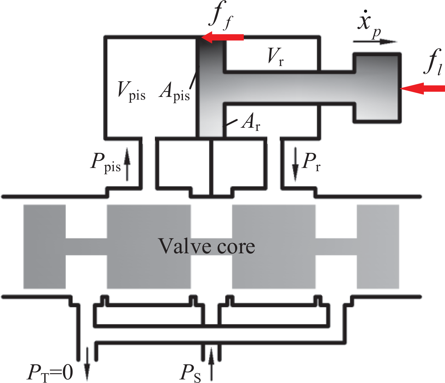
Asymmetric hydraulic cylinder controlled by symmetrical servo valve.

where subscripts p and n represent the extension and retraction of the piston, respectively. PS
and PT
represent the oil supply pressure and returning oil pressure, respectively.
Taking into account that the part has been turned into heat is difficult to quantify and denote, the power consumed by the hydraulic actuator can be denoted as

The force balance equation is given by

where fl is the external load, and ff represents the friction and damping inside the hydraulic cylinder and can be denoted as 21
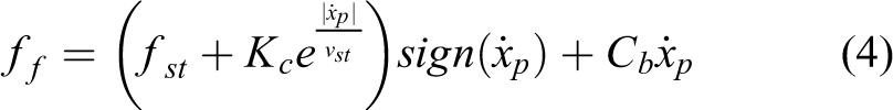
where Kc
and
Taking into account equations (2) and (3), the simplified form of the power consumed by the hydraulic actuator can be deduced as

Through integrating equation (5), the energy consumption of the actuator can be expressed as
Energy consumption model for SCalf-II
According to equation (5), load forces (

Hydraulic actuated robot SCalf-II. (a) Robot prototype; (b) front-left leg of SCalf-II.
Load force acting on actuator in supporting phase
Considering the symmetries of leg structure geometry designing, the front-left leg can be only used to establish corresponding models. In general, the swaying of hip assembly is not a rhythmic movement and has light contributions to the foot trajectory implementation. Accordingly, the rotating joints of thigh assembly and calf assembly are only considered in leg kinematics modeling. 12 With variables of front-left leg defining in Figure 3 and the corresponding values shown in Table 1, the foot position (Of ) in the reference coordinate system (O 0) at the rotating joint of hip can be described as

Definition of variables for front-left leg.
Leg specifications.


where joint angles

respectively.
Since the stability of the robot motion is not considered, the robot can be simplified to a planar model, as shown in Figure 4(a). In each gait cycle, the legs on two diagonals are either in the swing phase or supporting phase. Thus, the interaction force between the foot endpoint and the ground should be calculated during the supporting phase. Assuming no relative sliding and constant speed of the robot, the following relationships can be obtained by referring the two-dimensional (2D) planar model shown in Figure 4 (b) Simplified model of SCalf-II. (a): 3D translated into planar model; (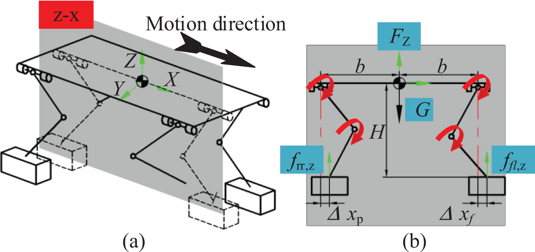

where b represents the length from the center of mass of robot’s torso to the hip joint. G is the weight of the torso, and
Then, taking equations (7), (8), and (9) into account, the torques on the joints can be calculated as

Taking the front-left leg as an example, the load forces on the piston can be calculated by equation (10)

where
Load force acting on actuator in swing phase
Again taking the front-left leg as an example, based on the Lagrange method, 23 the dynamics model of the leg can be written as follows

where the torque
And the load forces acting on actuators also can be calculated by equation (11).
Taking into account equation (14) and the robot structure shown in Figure 2, beside the gravity force, in the swing phase the load force acted on the actuators still includes the inertial force caused by rotation of leg components, and both of them manifest as a force that opposes motion during leg uplift stage. However, the gravity force manifest as a force that provides motive during leg falling.
Robot energy consumption modeling
Owing to the rhythm of the robot’s locomotion, the energy consumption of the legs on the diagonal in a gait cycle can be only considered and used to reflect the energy efficiency of the robot. Then, taking equations (6) to (12) into account, the energy consumption model of the robot can be deduced as follows

with the energy consumption of hip and knee actuators being expressed as follows
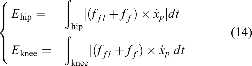
where the velocity of the piston
Gait parameters analysis
For the hydraulic servo actuator used on the quadruped robot, the piston diameter and oil supply pressure (PS ) are mainly determined by the weight and load capacity of the robot. The choice of the diameter of the piston rod also must consider the robustness of the structure. Once the structure is made certain, the parameters described above are also determined. Thus, from the energy conservation standpoint, the most effective way to reduce the energy consumption of the robot is to adopt the appropriate gait and foot trajectory with low energy consumption.
Foot trajectory of trotting gait
With larger adaptation range of the motion velocity and better energy efficiency, the dynamic trotting gait 24 is always an optimal choice for the motion of the quadruped robot. A gait cycle is composed of the swing phase and supporting phase, and the major controlling parameters in gait expressing equation are the step height, step length, and gait cycle.
A foot trajectory is planned with the goal of maintaining stabilization and continuation of the travelling speed of the robot, so it need to be representative and versatile. To assure the stability of torso’s traveling speed, the velocity of the foot trajectory along the direction travel should be formulated as constant during the entire gait period. Meanwhile, to acquire a better coordinated movement, the velocity and acceleration at the switching points of phase switching should be set to zero and of course include the highest point of the swing phase. Regarding the research on trajectory planning, many scholars have designed numerous functions such as curve-fitting, 25 cycloid functions, 26 and Bezier-curve functions. 27 Because of its better controllability of parameters and simple calculation, the curve-fitting method is the most commonly used.
For the foot trajectory planned by the curve-fitting method, the main controlled parameters include the step height, step length, and gait cycle, and step height has no contribution to the speed of the robot. On the basis of the above analysis and the study on the motion law of each actuators 28 in prior work, it can be concluded that the workable way to further change the energy consumption of SCalf-II is to control the velocity of leg uplifting and falling. To this end, the traditional curve-fitting method should be improved by adding another important controlled parameter. To meet this requirements, in the swing phase a piecewise continuous fitting curve is used in the z-axis and the equation can be written as follows

where H, L, and T represent step height, step length, and gait cycle, respectively. tf
is the time at which the step height is raised to the highest.
According to the description of stability and continuation of robot motion mentioned above, the constraint formulations are summarized as follows
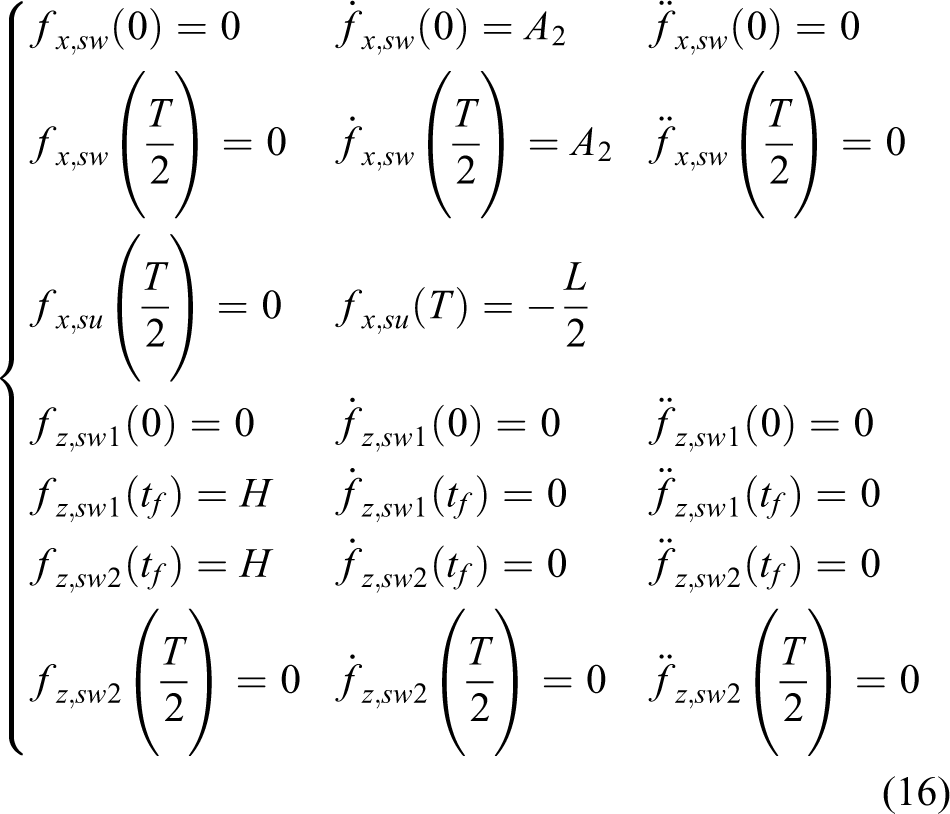
where formulas in the first and second lines are used to define the displacement, velocity, and acceleration of the foot endpoint along x axis in the swing phase with the time of 0 and
Simulation and analysis
Simulation setup
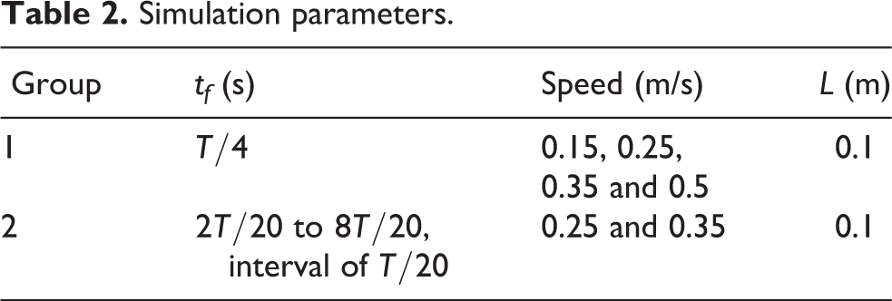
To obtain the variety of the energy consumption with different parameter combinations and find more ideal value range of the controlled parameters, two different simulation experiments were performed. The simulation settings are shown in Table 2. The computation time of each group is 10 s.
Simulation parameters.
Group 1 simulation results
Considering that two diagonal legs perform the same trajectory, the energy consumption of front-left and rear-right legs is only considered. The energy consumption of actuators at different parts of the legs is shown in Figure 5, parts of which are enlarged. The curves are drawn with the gait cycle T as the abscissa and the range of T between 0.1 s and 1 s is calculated. It can be seen from the results that as the gait cycle increases, the energy consumption of the actuators at the corresponding position of the front and rear legs is monotonically decreasing. Increase in gait cycle is always accompanied by decrease in the step length. Thus, the above data show that for the same speed, the model of low gait cycle and large step length consumes less power.

Energy consumption of actuators in group 1.
Figure 6 shows the total energy consumed by the robot. It can be seen from the results that the energy consumption decreases sharply with increasing the gait cycle when T is less than 0.6 s, while the change rate remains roughly constantly from 0.6 to 1 s. Thus, for the given foot trajectory, the ideal gait cycle should be greater than 0.6 s and the specific parameter can be determined according to the movement requirement of the robot.
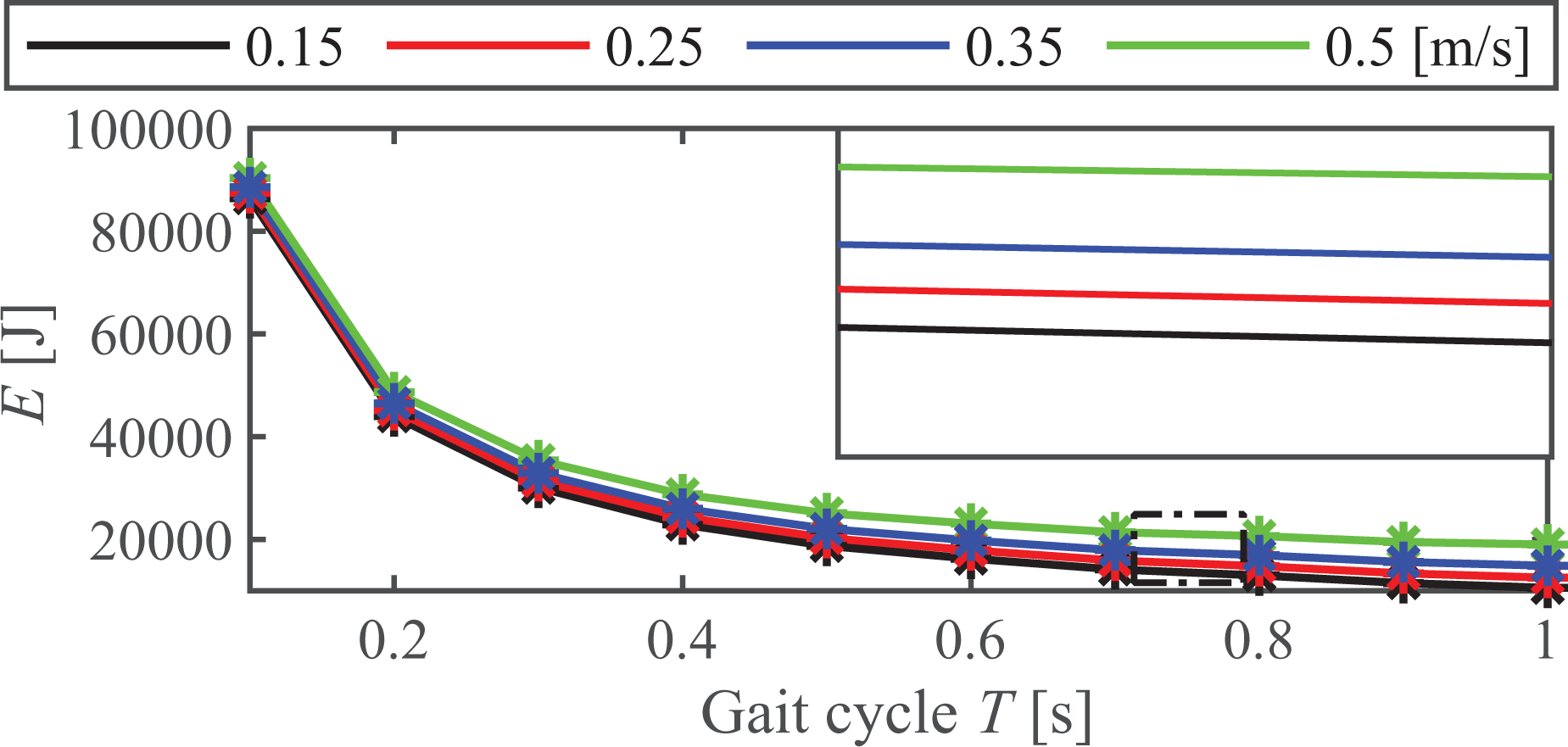
Energy consumption of robot in group 1.
Taking the speed of 0.15 m

Velocity of actuators in group 1.
Simulation results of group 2
In group 2, the foot trajectories with different tf values are shown in Figure 8. The gait cycle is set to 0.8 s, and the simulation results are drawn with the step length as the abscissa. As can be seen from Figures 9 and 11, with the exception of the hip actuator mounted on the rear-right leg, the energy consumption of the remaining actuators keeps monotonically decreasing. This phenomenon can also be explained by the velocity curves of the actuators.

Foot trajectories in group 2. A and B represent separation point and contact point between the ground and foot.
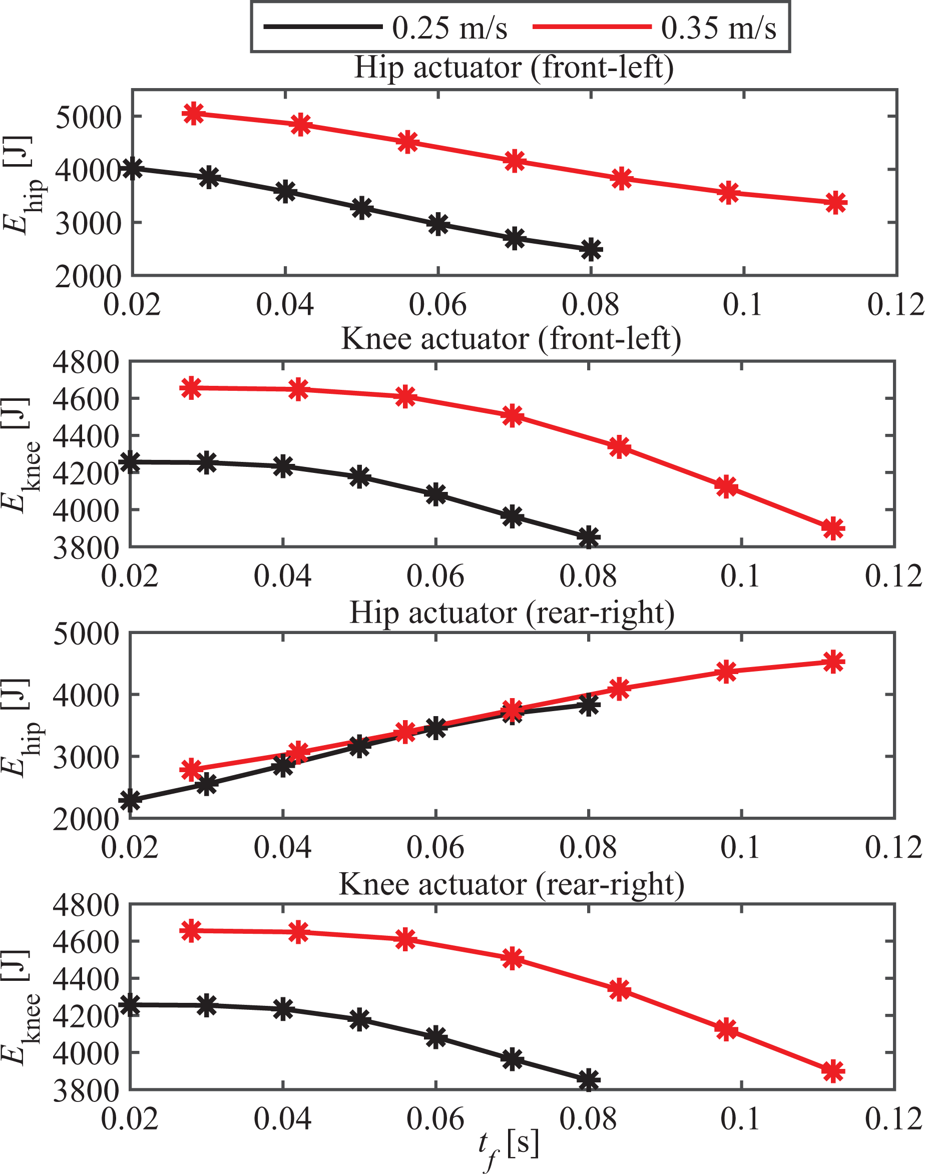
Energy consumption of actuators in group 2.

Velocity of actuators in group 2.

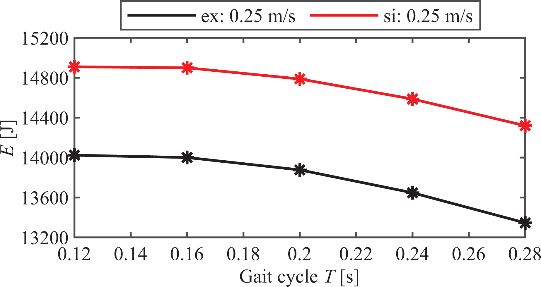
Energy consumption of robot in group 2.
Figure 10 shows the velocity of the actuators with different tf
values when the speed of the robot is 0.25 m
From the results of discussion, it is shown that when the gait cycle and the step length are determined, to further reduce the energy required during the locomotion of the robot, the process of leg lifting in the swing phase can be extended for as long as possible. Then a shorter time of leg lowering means that the foot may be in contact with the ground at a greater speed (especially in unstructured terrain), thereby increasing the impact and affecting the stability of the robot. Thus, the actual parameters of the foot trajectory still should be determined according to the movement requirement of the robot.
Experimental verification
Experimental setup
The power of SCalf-II is provided by a single cylinder petrol engine with a constant rotational speed of 10000 rpm. The flow supplied by the combination of the petrol engine and a variable displacement piston pump with a displacement of 4 ml
The load forces acted on the actuators can be obtained by the force sensor mounted on the piston, and the velocity of the piston can be calculated by differential of the data collected by the displacement sensor.
The experiment was also divided into two groups and carried out sequentially with reference to the simulation setup process. Considering the stability of SCalf-II in the movement process, the experimental settings are detailed in Table 3. In group 2, five gait cycles are adopted: 0.4, 0.5, 0.6, 0.7, and 0.8 s. To ensure a high trajectory tracing accuracy, position control is adopted.
Simulation parameters.

In the experiment, each test was repeated three times for a duration of 10 s each time. The average value of the three experiments is used for comparison and analysis.
Experimental results
Figures 12 and 13 show the experimental results in group 1. In each images, the simulation results are also drawn for comparison.

Experimental results of actuators in group 1. Solid line and dotted line represent the experiment results (

Experimental results of robot in group 1. Solid line and dotted line represent the experiment results (
As can be seen from the results, the energy consumption of SCalf-II obtained using the energy calculation model expressed in equation (14) is very close to that of the experimental results, which indicates that the model has high reliability for predicting the energy consumption of a hydraulic actuated quadruped robot. Owing to the limitation of the stability of SCalf-II, the tests under the remaining gait cycles were not carried out. However, from the comparison with simulation results, the law of energy consumption concluded in the section of the group 1 simulation results is still met. The experimental results are smaller than the simulated values with the same conditions. The reason for this is that the data of the displacement and velocity applied in the calculation are provided by the linear displacement sensor, which has a static error (less than 1 mm) with the theoretical value. Moreover, the mathematical modeling is an approximation of the realistic robot system, so the error is inevitable.
The experimental results of group 2 are shown in Figures 14 and 15. The predicted results of the mathematical model accord well with the observed data, and the law concluded in the section of group 2 simulation results is also met.

Experimental results of actuators in group 2.
Experimental results of robot in group 2.
The above experiments show once again that, for hydraulic actuated quadruped robots with a similar structure to SCalf-II, the larger the gait cycle adopted, the less energy is required by the robot with the trotting gait at a constant speed. When the proper gait cycle is determined, energy consumption can be further reduced by extending the time of leg lifting in each cycle.
Conclusions
In this work, based on energy consumption model of the hydraulic actuator, the energy consumption model of the quadruped robot, SCalf-II, is established firstly. Then, combining the analysis on load characteristics and of the actuators and the previous research, the foot trajectory characterized by using segmented cubic spline interpolation curve in the swing phase is proposed, which is to reduce the energy consumption of the robot through introducing the controlled parameters tf
to change the duration of leg raising and falling in one gait cycle. Eventually, the variation of energy consumption affected by the controlled parameters of gait cycle and tf
is obtained by simulation and the corresponding experiments for verification are also carried out. The results provide principle for the selection of controlled parameters for robot locomotion. For instance, the theoretical value of the gait cycle should be greater than 0.6 s, and for tf
the theoretical value should be greater than
Footnotes
Declaration of conflicting interests
The author(s) declared no potential conflicts of interest with respect to the research, authorship, and/or publication of this article.
Funding
The author(s) disclosed the receipt of the following financial support for the research, authorship, and/or publication of this article: This work is supported by the Nature Science Research Project of Anhui province (NO. KJ2020A0287), the National Natural Science Foundation of China [Grant No. 91748211, 61973135, 62072191, 91948201], the Opening Project of Shanghai Robot R & D and Transformation Functional Platform [Grant No. k2020468].
Appendix 1
The velocity of piston can be obtained by differentiating equation (7), which yields
where
The actuator’s length can be expressed as the function of the joint angle, and the expressions are defined as follow
where auxiliary angles
respectively.
Then, the effective lever arm of the actuator is deduced as
where auxiliary angles
respectively.
The 2
where mu and md represent the mass of thigh an calf of the robot, respectively. Iu and Id are the moment of inertia with respect to its center of mass, respectively.
The 2
and
where g is the gravity acceleration.