
Abstract
This article presents a mechanical design structure for hydraulic actuators using the principle of series-elastic actuator, considering the restriction of mechanical structure, weight and size, as well as the requirement of high joint torques due to the large payload. An articulated leg was designed to incorporate with two of these elastic elements symmetrically for each joint. Further, for the hydraulic system with a position servo loop, a force control algorithm was particularly proposed and developed for joint torque tracking and Cartesian impedance control. Finally, a number of experiments were carried out on the leg platform, and the experimental results validated the effectiveness of the force control algorithm and the performance of the overall system.
Keywords
Introduction
With good adaptability to new environments and flexibility of movements, quadruped robots have the capability of agile, stable manoeuvre and traversability in uneven and rugged terrains. Thus, they have broad application prospects. 1 –3 In particular, hydraulic quadruped robots, such as BigDog, 4 HyQ 5 and LS3, 6 powered by hydraulics are commonly developed to carry heavy payloads due to the high power-to-weight ratio. It is of vital importance for quadruped robots to walk stably in unknown environments by selecting proper force-controlled actuators and adopting appropriate force control algorithms.Because of incompatible problems of force/energy density and output impedance of the traditional rigid actuators, a type of force-controlled actuator – series-elastic actuator (SEA) is selected to be applied to the articulated legs of legged robots. 7 –9 It is well known that SEA has good mitigation effects on impacts, capacity of energy storage and release, precise and stable force tracking control and can effectively deal with the foot–ground interaction for legged robots. 10,11
In the literature, there are lots of researchers dedicated into development of SEAs. SEA was first proposed by Pratt and Williamson has shown remarkable impact tolerance and small mechanical joint impedance. 12 Based on this, a compact rotary SEAs and related force control have been designed for human assistive devices. 13,14 Kalouche et al. has proposed a set of modular SEAs and then developed them into SEA Snake. 15 Later, a multi-modal legged robot platform Snake Monster has been reconfigured. 16 agile and dexterous robotics lab (ADRL) at Swiss Federal Institute of Technology (ETH) has designed a serial elastic compliant quadruped robot StarlETH and showed that SEA not only protects the motor from impact, but also temporarily stores energy. 17,18 Subsequently, the team has applied a highly integrated SEA – ANYdrive into a quadruped robot ANYmal. 19
Valkyrie, a humanoid robot with many series elastic degree-of-freedoms (DoFs) has been designed by NASA-JSC. Then, a decentralized torque control architecture has been proposed, which demonstrated torque control capability on Valkyrie. 20 Hutter et al. summarized and compared legged prototypes – FerrETH with SEA and ScarlETH with series damping actuation. The cascaded control structure has also been applied to the compliant legs that can achieve precise joint torque and position control performance. 21
However, as far as we know, few SEAs are used in hydraulic quadruped robots over 150 kg. The research in this article aims to address this challenge. As shown in Figure 1, we present a two-DoF planar articulated leg unit for hydraulic quadruped robots. 22,23 According to the required joint torques of quadruped robots, the elastic elements and an articulated leg have been designed to meet these specifications. Moreover, based on kinematic parameters of the articulated leg, the position servo of the highly integrated valve-controlled cylinder (HIVC) is used for the joint torque tracking using the SEA principle. The joint torque tracking and impedance control algorithm in Cartesian space have been formulated and implemented. Finally, a series of experiments including impact tests have been carried out, and the effectiveness of the force control algorithm and reduction of ground impacts were fully validated.

Articulated leg with SEA for a hydraulic quadruped robot. The angle sensors are assembled on each joint. Force and position sensors are on a HIVC. SEA: series-elastic actuator; HIVC: highly integrated valve-controlled cylinder.
The remaining of this article is organized as follows. The second section presents the mechanical design of the SEA-based articulated leg and specifications of the elastic element design. The third section elaborates the details of force control scheme for the articulated leg with SEAs. The fourth section provides experimental results of joint torque tracking and Cartesian impedance control tested on the articulated leg. Finally, the conclusion and future work are drawn in the fifth section.
Design of an articulated leg with SEA
Based on the previous quadruped robot design, 24,25 we choose a sagittal two DoFs articulated leg structure, as shown in Figure 2. The corresponding kinematics parameters are illustrated at the Table 1.
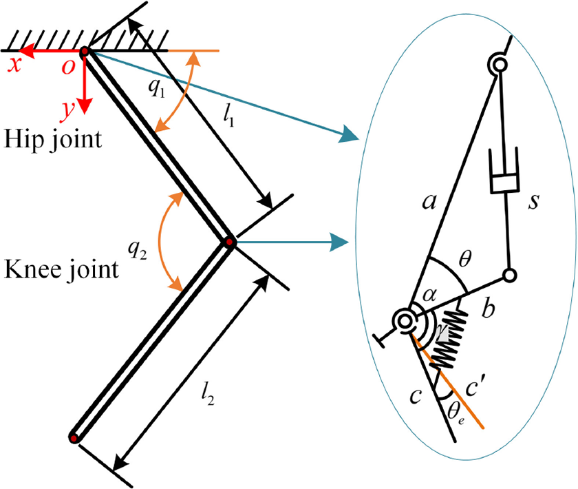
The simplified model of an articulated leg with two revolute joints.
Kinematic parameters.

According to Figure 2, the joint angle α can be obtained as follows

where θ indicate the angle between drive rod (b) and fixed link (c); γ represents the initial constant angle value between the drive rod (b) and the initial load link (c) as shown in Figure 2,
In general, hydraulic quadruped robots are usually developed designed for carrying heavy loads, so each joint has to bear a large torque. Based on the weight and joint configuration of hydraulic quadruped robots, assuming the maximum bearing torque and torsion angle of each joint can up to 100 Nm and 10°, respectively. According to the requirement of maximum bearing torque of each joint and torsion angle range of the elastic element, the double spring design 26 (see Figure 1) is a better choice than other elastic elements. 27 –29 Therefore, the elastic elements required for each joint are as follows

where
To design the required elastic elements, we use SolidWorks to carry out 3D mechanical design and import it into the finite element analysis software ANSYS Workbench. Through finite element analysis, the key parameters, such as maximum stress and torsion angle of the elastic element under static load have been mainly studied.
According to the relevant knowledge of material mechanics, it can be known that the stiffness coefficient can be changed by adjusting the width of the spiral groove and the overall thickness of the elastic element. The material chosen for the elastic element is 60Si2Mn spring steel, which is a widely used silico-manganese spring steel with yield strength σs = 1175 MPa and elastic modulus E = 190 GPa. Combined with simulation analysis, we design several elastic elements with different thickness to select the required stiffness gain.
Elastic element stiffness measuring platform, as shown in Figure 3, is mainly composed of four parts: SEA wheel, shaft support, angle measuring device and weight plates. The torques on the elastic elements are loaded by some grip plates with a mass of 2.5 kg. Loading experiments have been carried out by means of average measurements for several times.
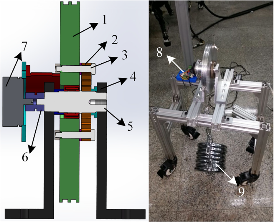
Mechanical structure and platform of the SEA stiffness measuring prototype: (1) pulley, (2) elastic element, (3) pin, (4) shaft support, (5) spindle, (6) coupling, (7) angle sensor, (8) angle measuring device and (9) grip plates. SEA: series-elastic actuator.
The stiffness gains of the elastic elements can be determined by Hooke’s law

where Ke is the stiffness gain of the elastic element, Vm is the range voltage value of the angular sensor sensor, δτ indicates the measured torque and δV indicates the measured voltage.
From the measurement results (see Figure 4), the hysteresis phenomenon of stiffness curve is not obvious. It can be seen that the difference between loading and unloading does not significantly affect the stiffness of elastic elements.

Torque–voltage profiles for measuring SEA stiffness gain. Left chart shows the forward loading and unloading result, and right chart shows the reverse loading and unloading result. Blue ‘+’ represents a GI in load, red ‘×’ indicates a GD in load and black solid line ‘–’ indicates LSF curve. SEA: series-elastic actuator; GI: gradual increase; GD: gradual decrease; LSF: least squares fitting.
By measuring elastic elements with different widths via SEA stiffness measuring platform, the elastic element with a width of 15 mm is finally selected. The forward stiffness of the elastic element is 5.14 Nm/° and the reverse stiffness is 4.83 Nm/°. To meet the design requirements, we assembled two pieces of the elastic elements symmetrically in each revolute joint. Thereby, the stiffness gain of the joint is close to 10 Nm/°. Table 2 displays the parameters of the elastic elements.
Parameters of the elastic element.

HIVC: highly integrated valve-controlled cylinder.
The mechanical structure of each revolute joint with SEA is shown in Figure 5. The drive rod is connected with the spindle via a square key, which converts the force transmitted by the hydraulic rod into joint torque and transmits it to the spindle. The inner ring of the elastic element is connected with the square key of the spindle, and the outer ring is connected with the lower limb of the joint through the pin. Angle sensor is connected with the spindle via an elastic coupling for measuring the relative rotation angle between the lower limb and the joint axis. That is, the torsion angle of the elastic element. Voller pin bearings and self-lubricating gaskets are also assembled for reducing friction. On the basis of SEA joint design, a new prototype of an articulated leg is manufactured as shown in Figure 1.

CAD model of a hydraulic leg’s joint with SEA built in SolidWorks. (a) Front and side view of 3D CAD model of a single joint with SEA. (b) Cross section of the CAD model of SEA joint of the leg: (1) angle sensor, (2) coupling, (3) elastic element, (4) pin, (5) thigh link, (6) spindle, (7) drive rod and (8) crus link. CAD: computer-aided design; SEA: series-elastic actuator.
Force control algorithm
Generally speaking, an articulated leg with SEA is used for compliance quadrupedal locomotion for reducing impact and improving force tracking control. Due to the introduction of SEA, the joint torque could be tracked via controlling the angle of the elastic element. Therefore, in this section, we use a position servo controller of the HIVC for tracking the joint torque.
As shown in Figure 6, a reference torque of the revolute joint with SEA can be tracking via HIVC position servo and measured angle signals. The actual joint torque can be obtained by measuring the deformation of the elastic element

Block diagram of joint torque tracking controller.
where
Similarly, the desired joint torque is determined as follows

where
To track the desired torque, the deviation angle between desired and actual torque is as follows
with

According to Figure 2, the reference angle between the drive rod and the fixed link can be calculated

with

where s indicates the position of the HIVC. a and b as shown in Figure 2.
Based on cosine theorem, the reference position of the HIVC is as follow

The reference position control signal is obtained from the joint torque deviation, so that the joint torque error can be compensated for realizing reference torque tracking.
In the simplified linear model of flow valve-controlled hydraulic cylinder, the output flow of the valve is proportional to the input control current signal. And the output flow of the valve enters the two chambers of the hydraulic cylinder to drive the piston to move. Therefore, position-based servo control performance of the HIVC can be well controlled by choosing flow servo valve. Position-based servo control signal of the HIVC adopts proportional–integral control

where kp and ki indicate proportional gain and integral gain, respectively. sd and sa are desired and actual position of HIVC.
Based on the previous study, the joint torque tracking bandwidth between 1 Hz and 1.5 Hz can meet the locomotion requirement. From the principle of SEA torque servo control, it can be concluded that the position response frequency of the hydraulic actuator is consistent with that of joint torque response frequency. Thereby, we carried out several experiments to validate the response frequency and position servo accuracy of the HIVC with 1 and 1.5 Hz.
Figure 7 shows the position tracking error of the HIVC is about ±0.3 mm for 1 Hz and ±0.4 mm for 1.5 Hz, respectively. Position tracking accuracy is within the control tolerance, which can be used for joint torque tracking controller.

Results of the position tracking of the HIVC. (a) Profile of the HIVC tracking position signal with 1 Hz. (b) Profile of the HIVC tracking position signal with 1.5 Hz. HIVC: highly integrated valve-controlled cylinder.
Based on the motion planning of quadrupedal locomotion, the trajectories of each foot are generated by walking pattern generation in task space, namely Cartesian space. 30 Therefore, we use an impedance model in Cartesian space to deal with foot–ground interactions. 24,25
The desired forces fd in Cartesian space generated by the Cartesian space impedance model can be calculated by

where Kp
and Kd
indicate stiffness and damping coefficients of the impedance model in Cartesian space.
Therefore, desired joint torques of the articulated leg can be obtained via Jacobian transposition

Then reference torque can be realized by a joint torque tracking controller. The block diagram of the force controller for an articulated leg with SEA is shown in Figure 8.

Block diagram of force controller for an articulated leg with SEA. SEA: series-elastic actuator.
Results
In this section, we have implemented a set of experiments to validate the effectiveness of the force control algorithm. The experiments were carried out on an articulated hydraulic leg platform as shown in Figure 9. The results of joint torque tracking and Cartesian impedance control are presented and analysed for evaluating the performance.Joint torque tracking
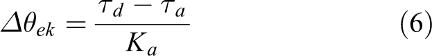
Through the analysis of the control algorithm in the previous section, it can be concluded that the control accuracy of the joint torque tracking depends on the position servo accuracy of the HIVC. Through a numerical analysis based on theoretical model of SEA torque control, the relationship between the joint torque error and the position deviation of the HIVC can be obtained by equations (6), (7) and (9)

Articulated leg platform of a hydraulic quadruped robot.

with

where
Assuming the position control error along the cylinder of the HIVC is Δs = ±0.3 mm, the corresponding joint torque errors caused by rotational deflection of the elastic element in hip and knee joints are numerically analysed as follows.
According to kinematic parameters of the articulated leg, the common HIVC range of motion of hip and knee joints are both 245 ± 25 mm. As shown in Figure 10, the mapping between the joint torque and the linear position deviation is non-linear, and the maximum joint stiffness (hip and knee) that can be achieved 4 Nm and 5.5 Nm, respectively.

Profile of the HIVC position and torque errors of (a) hip joint and (b) knee joint with SEA. HIVC: highly integrated valve-controlled cylinder; SEA: series-elastic actuator.
Moreover, joint torque tracking experiments were also implemented. The dynamic torque tracking performance for large range motion of joints were tested. Joint torque tracking signal, joint angle and position tracking error of the HIVC were illustrated in Figure 11.

Profile of zero-torque tracking of hip and knee joints. (a) Zero-torque tracking curves of hip joint. (b) Zero-torque tracking curves of knee joint.
From the zero-torque tracking curves, it can be seen that the torque tracking errors of two joints are within 2–3 Nm; from the position error of the HIVC, the average position errors of the hip and knee joints are within ±0.6 and ±0.4 mm, respectively. Compared with the conservative theoretical derivations and numerical analysis (Figure 10), the experimental results have better performance of joint torque tracking accuracy.
The reason is the incorporation of elastic elements in all joints reduces the vibration of joints and the HIVC position servo. In addition, the elastic element reduces torque variation, given the same position error, and, therefore, improves the accuracy of torque tracking, which is also the advantage of the SEA.
Besides, we also implemented a constant 30 Nm joint torque tracking experiment. The results are shown in Figure 12. Comparing the joint torque tracking experiments of 0 and 30 Nm, the torque error of two joints at 30 Nm is basically the same as that of the two joints at 0 Nm. Static joint torque servo accuracy is approximately 2% that is within the control tolerance.

30 Nm torque tracking of hip and knee joints. (a) Joint torque tracking of hip. (b) Joint angle of hip. (c) Joint torque tracking of knee. (d) Joint angle of knee.
Impedance control in Cartesian space
To validate the effectiveness of the Cartesian impedance control algorithm, we carried out experiments of the articulated leg without force sensors on foot. Based on the Jacobian relationship of joint torques and contact forces, we set horizontal and vertical stiffness gains to be 1 Nm/°. In the experiment, position disturbances are applied to the foot manually with the articulated leg fixed in air.
As shown in Figure 13, joint torques can accurately track the desired references of hip and knee joints, and errors of joint torques are within ±2 Nm. From this, the tracking accuracy of joint torques is calculated to be less than 5%, which meets the system requirements.

Experimental results with horizontal and vertical stiffness of 1 Nm/°: (a) and (b) illustrate foot position of x- and y-axes; (c) and (d) illustrate the torque tracking curves of hip and knee joints and (e) and (f) are torque tracking errors of hip and knee joints.
Moreover, we choose different Cartesian space impedance parameters. During stance phase, a larger vertical stiffness gain is needed to support the torso than horizontal stiffness gain. This is because horizontal contact forces are provided by friction, while the friction force is much smaller than that in the vertical direction. Therefore, we choose horizontal stiffness gain of 0.5 Nm/° and vertical stiffness gains of 5 Nm/° (test 1) and 20 Nm/° (test 2), respectively.
The experimental results of these two set-ups are shown in Figures 14 and 15 with the foot position of x- and y-axes and torque errors of the hip and knee joints. We can see that the tracking accuracy of hip and knee joint torques are nearly 10% and 5%, respectively.

(a to f) Experimental results with a horizontal stiffness gain 0.5 Nm/° and a vertical stiffness gain 5 Nm/°.

(a to f) Experimental results with a horizontal stiffness gain 0.5 Nm/° and a vertical stiffness gain 20 Nm/°.
In addition, one important advantage of articulated legs with SEA is to improve the compliance of leg and mitigate the ground impact. Therefore, we carried out one more free-fall experiment with a foot height above 100 mm. Figure 16 shows the experimental results with three impacts on the foot and ground with a horizontal stiffness gain of 0.5 Nm/° and a vertical stiffness gain of 10 Nm/°.As can be seen from Figure 16, the force control in hip and knee can track the desired torques effectively. In other words, in the situation of large impact, the joint torque tracking performance is still quite well. Figure 17 depicts the snapshots of the impact experiment. Experiments show that the hydraulic leg still preserved the expected impedance characteristics during a large impact, which validates the effectiveness of our proposed force control algorithm and its robustness against the unknown external disturbance.
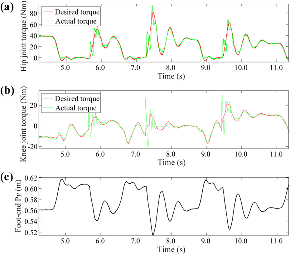
Results of three foot–ground impact experiments show that the height of foot fell freely from above 100 mm (horizontal stiffness gain 0.5 Nm/° and vertical stiffness gain 10 Nm/°). (a) and (b) Show the desired and actual hip and knee joint torques, respectively and (c) shows the foot position in y-axis.
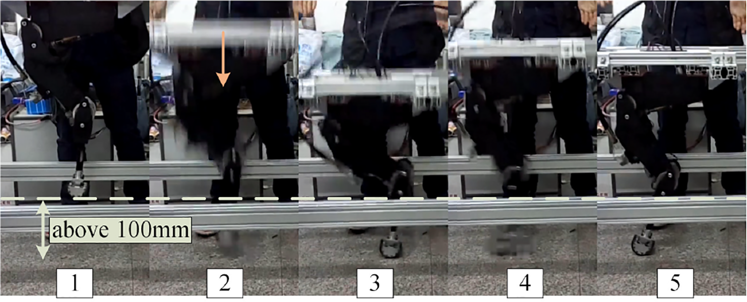
The snapshots of foot–ground impact experiments.
Conclusions and future work
This article studies an articulated leg with hydraulic SEAs for a quadruped robot. Aiming at the requirement of joint torque control of hydraulic quadruped robots, elastic elements with a large payload and high stiffness gain were designed by a stiffness measuring set-up using the existing elastic materials. Based on that, a revolute joint with two SEAs and an articulated leg of the hydraulic quadruped robot have been designed.
Furthermore, the force control algorithm of the articulated leg is particularly researched. Experiments, such as joint torque tracking, impedance control in Cartesian space at foot and ground impact test of the leg, validate the rational design choice of using SEA joints and the effectiveness of the force control algorithm. The study lays a good foundation for the application of hydraulic SEA on hydraulically powered quadruped robots.
However, there are some limitations in this study. Because the joint torque requirements of hydraulic quadruped robots are exceptionally high, the size of elastic elements and the hydraulic joints becomes larger, and the structure is more complicated. In the future, we would like to choose different materials with higher strength and greater elastic modulus, so we can re-optimize the mechanical design of the joint structure. In addition, we will further establish the system models of HIVC and analyse the control characteristics of the hydraulic system to provide a theoretical basis for the force control system of quadruped robots.
Footnotes
Declaration of conflicting interests
The author(s) declared no potential conflicts of interest with respect to the research, authorship, and/or publication of this article.
Funding
The author(s) disclosed receipt of the following financial support for the research, authorship, and/or publication of this article: This work was supported by Natural Science Foundation of China [No. 61773139], Shenzhen Special Fund for Future Industrial Development [No. JCYJ20160425150757025], Shenzhen Science and Technology Research and Development Foundation [No. JCYJ20190813171009236] and Shenzhen Science and Technology Program [No. KQTD2016112515134654].