
Abstract
Topology optimization is an effective method for the lightweight of collaborative robots. The extreme working conditions of the robot for the existing topology optimization approach are usually determined by design experience, which may cause mismatch between the chosen load boundary condition of the parts to be optimized and the actual maximum one. In this article, a kind of topology optimization method based on orthogonal experiment was proposed to avoid this mismatch. For this method, the extreme working condition of robots was determined by finding out the combination of robot joint angles when the stress of the part was maximum based on orthogonal experiment. And then, the structure of the part was optimized with the objective of minimizing mass and the constraint of the maximum end displacement of the robots. Finally, the proposed method and the existing method were applied to the lightweight design of a 7 degree of freedom upper limb powered exoskeleton robot, and the results demonstrated that the presented approach can reduce 6.78% maximum end displacement of the robot on average compared with the existing one. It can be concluded that the proposed method in this article is more reasonable and applicable to the structure optimization of collaborative robots.
Keywords
Introduction
With the rise of the new working mode of human–robot collaboration in health care, services, and other unstructured unknown scenes, 1 –4 the safety of the robots has caused much attention. Safety can be increased by reducing the mass and inertia of robots because the harm of the collision between machine and human body 5 could be weakened when the mass and inertia of robots become smaller. Therefore, the lightweight design plays a significant role in improving the safety of robots, 6,7 which can be achieved using new lightweight materials or optimizing the structures of parts. 8 –10
To reduce the mass of robots, many researchers employed new lightweight materials in their designs. Albuschaffer et al. replaced the traditional metal materials with high-strength carbon fiber as the material of the robot link to reduce the quality of the DLR lightweight robots. 1 Schrock et al. designed the wheelchair-mounted robot with the new materials of polycarbonate and carbon fiber to achieve the purpose of lightweight design. 11 Considering that new lightweight materials are usually expensive and difficult to be machined, 8 structure optimization including size optimization, shape optimization, and topology optimization has become the main way to achieve lightweight design due to the advantage of low cost and sophisticated technology. 12,13
In the work of Zhang et al., a lightweight, high stiffness, and compact robot was designed by the integrated modular structural design approach based on dynamic and finite element method. 14 Yin et al. proposed a structural optimization method for the lightweight design of robotic arms by parameterizing the structural dimensions and drive trains as design variables, and the validity and advantage of the method were illustrated by a design example. 15 These two studies were carried out based on size optimization and shape optimization. Comparing to the above two methods, topology optimization does not simply modify the existing structures but gives new layouts, which can effectively shorten the development cycle of the products and means greater design freedom. 16 For this reason, topology optimization has been widely applied in aircraft, automobile, and robot areas. 17,18
Many topology optimization approaches have been proposed for the lightweight design of robots. Albers and Ottnad applied topology optimization to the lightweight design of the ARMAR III humanoid robot by minimizing the mass of the robot’s thorax under compliance constraints. 19 Lohmeier et al. reduced the mass of humanoid walking robot Lola using a similar method. 20 Kim et al. 13 employed a kind of topology optimization approach based on part-level metamodels for the lightweight design of industrial applications of serial robots by reducing the mass of a robot’s base frame, upper frame, and lower frame. Huang et al. optimized the Motorman-HP20 robot’s L-shape arm by defined the rotation with the maximum acceleration of it in horizontal attitude as topology optimization extreme working condition of the parts based on experience. 21 Bai et al. optimized the structure of the SR-165 robot’s upper arm based on horizontal lifting posture, which was also determined by experience. 22 The topology optimization extreme working conditions of these studies mentioned above, composed of the robot joint angle combination and external load, were usually determined by design experience. We defined this kind of method as experience-based working conditions topology optimization (EWC-TO).
However, before the material removal, the stress distribution of the parts to be optimized needs to be achieved by finite element analysis (FEA) based on these conditions in topology optimization. 6 And these extreme working conditions in EWC-TO may be different from the actual ones as the motion of collaborative robots achieved by the angle variation of its multiple joints is complex. It will cause that the load boundary conditions of the parts deviate from the real maximum one, which would eventually affect the performance of the parts. To solve this problem, a new topology optimization method defined as orthogonal experiment-based working conditions topology optimization (OEWC-TO) was proposed, where the extreme working conditions were determined by orthogonal experiment. 23,24
The rest of the article is organized as follows: Firstly, the basic principles and steps of the OEWC-TO method were described in the second section. And then, this method was applied to the lightweight of a 7 degree of freedom (DOF) upper-limb powered exoskeleton (ULPE), and the results were compared with those obtained by the EWC-TO method in the third section. Finally, the conclusion was shown in the fourth section.
Introduction of the robot lightweight design method based on OEWC-TO method
The introduction of FEA and topology optimization
The stress distribution of parts to be optimized can be calculated by applying FEA on the robots under extreme working conditions. Firstly, the finite element mesh of the model is generated for analysis, and the element is connected by nodes. Then, the element stiffness matrixes

where

where
The topology optimization of the part for the lightweight design of the robot can be carried out based on FEA, of which the equation (2) is used as the boundary condition during optimization, with the objective of the minimized mass of the structure to be optimized. The mathematical model of topology optimization can be built based on the Solid Isotropic Material with Penalization method, 25 shown as following equations:
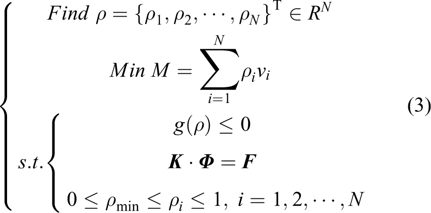
Where
Thus, the load boundary conditions, determined by the extreme working condition of the robots, are the main difference between OEWC-TO and EWC-TO. The extreme working conditions of the OEWC-TO are determined by acquiring the specific joint angle combination of robots based on orthogonal experiment, with which the stress of the part is maximum, while the EWC-TO is determined by experience, which will lead to the load boundary conditions being less than the actual one. As a result, the redesigned structures of the parts based on OEWC-TO are better than those based on EWC-TO.
For the sake of simplicity, the FEA and topology optimization of lightweight design were conducted by the software ANSYS Workbench (ANSYS, Canonsburg, PA, USA) in this article.
The basic steps of OEWC-TO method
For the lightweight design of a serial robot-like ULPE, the process of OEWC-TO can be described as follows: 1. Establish orthogonal table of joint angle of robots
Theoretically, the FEA of the parts for topology optimization should be carried out based on every joint angle combination of robots throughout the whole workspace. Considering that the FEA results of the parts under all working conditions are too hard to be obtained, it is necessary to determine the specific joint angle combinations of robots which make the stress of the corresponding part maximum, using orthogonal experiment based on the joint angles in the range of motion including initial, end, and other representative angles. And the orthogonal table of the orthogonal experiment is established with the factors (joint angles of the robots) and levels (the value of the joint angles). Based on the joint angle combinations of robots obtained by orthogonal experiments, extreme load boundary conditions of the parts for topology optimization can be determined.
2. FEA based on orthogonal table
The FEA of the parts is carried out with the joint angle combinations of robots in the orthogonal table determined in step (1). The joint angular acceleration and end load are set as the maximum values. The steps of FEA also contain simplifying model, adding material, generating the mesh, setting constraints and load, and post-processing. Then, the extreme load boundary conditions of the parts to be optimized for topology optimization could be obtained by analyzing the results of FEA.
3. Topology optimization of the parts based on the extreme load boundary conditions
The optimization of the parts can be conducted based on the extreme load boundary conditions obtained in step (2) with the objective of the minimized mass of the structure. Considering that the ULPE robot is designed for rehabilitation training, the end displacement of the robots is set as the constraint of optimization to avoid the negative influences brought by large end displacement.
According to the process above, the lightweight design of the robots can be realized by the optimization of the parts.
Application of the OEWC-TO method
Establishment of orthogonal table of robot joint angles
The 7 DOF ULPE robot was designed for the upper limb rehabilitation training of wearers with the 5-kg rated load and 905-mm maximum reach, and the OEWC-TO method was applied to the robot to achieve the lightweight design. The joint distribution of the robot is shown in Figure 1(a), and the parts to be optimized for the lightweight design of the robot are determined based on engineering practice. The models of parts are demonstrated in Figure 2. In this article, we only considered the angle changes of the shoulder and elbow joints of the robot when the topology optimization of the parts was carried out because the influence of wrist joints’ motion on the load boundary conditions could be ignored. The range of the joint angles is shown in Figure 1(b), and the specific kinematics and dynamics parameters are listed in Table 1.

Solid CAD model and joint motion range of the 7 degree of freedom upper limb powered exoskeleton: (a) joints of the model, (b) range angles of the shoulder and elbow joints of ULPE robot.

The parts to be optimized of the robot: (a) J1base, (b) J3-4C1, (c) J3-4C2, (d) J3-4C3, and (e) J4-5.
The kinematics and dynamics parameters of ULPE’s shoulder and elbow.

DOF: degree of freedom; ULPE: upper-limb powered exoskeleton
According to the data listed in Table 2, L16(44) is selected as the orthogonal experimental table in this orthogonal experiment, as shown in Table 3.
Factors and levels of orthogonal experiment.*
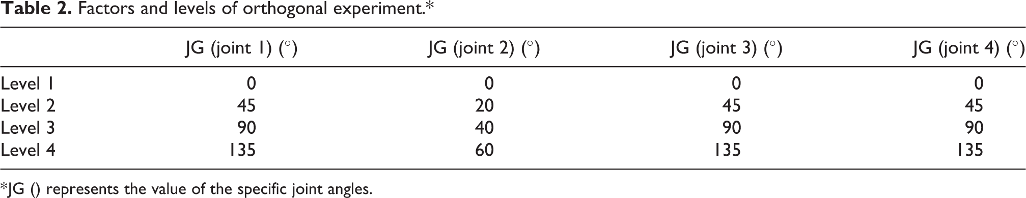
* JG () represents the value of the specific joint angles.
Orthogonal experimental table.*
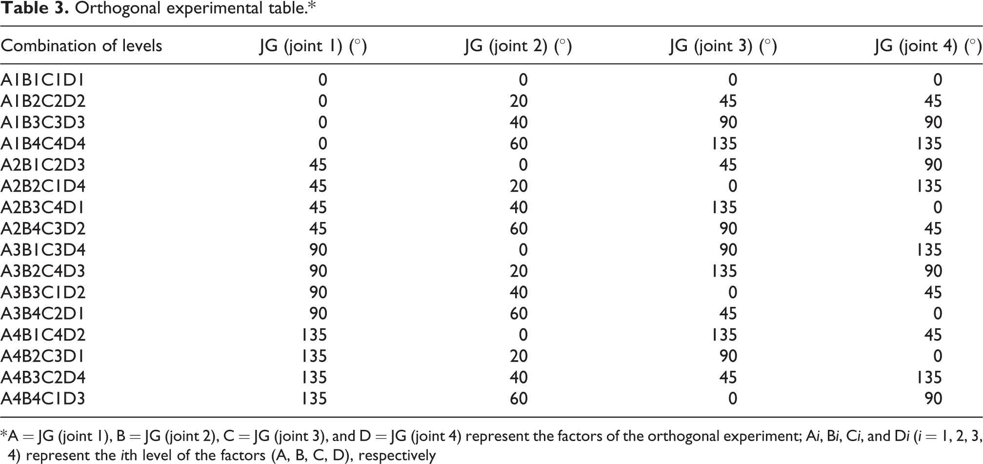
* A = JG (joint 1), B = JG (joint 2), C = JG (joint 3), and D = JG (joint 4) represent the factors of the orthogonal experiment; Ai, Bi, Ci, and Di (i = 1, 2, 3, 4) represent the ith level of the factors (A, B, C, D), respectively
FEA of parts based on orthogonal table
Firstly, the FEA of the parts to be optimized is carried out based on the orthogonal table, and then, the joint angle combinations of the robot can be screened out by the results, resulting that the extreme load boundary conditions of parts are consistent with the actual maximum one when the topology optimization is carried out. The results were obtained by calculating after the following steps: simplifying the model of the robot, defining the material of the parts, generating the mesh of the model, and setting the load and constraint boundary condition. The mesh model of the ULPE robot with the joint angle combination of A2B4C3D1 is shown in Figure 3, and the stress and deformation are shown in Figure 4.

Mesh model of the upper limb powered exoskeleton robot of which the joint angle combination is A2B4C3D1.

The finite element analysis results of the upper limb powered exoskeleton robot with the joint angle combination of A2B4C3D1: (a) stress of the assembly and (b) deformation of the assembly.
The range analysis of the results of FEA was carried out to determine the joint angle combinations of the robot for topology optimization of parts. The range analysis data of the maximum stress of J1base are listed in Table 4 and shown in Figure 5. A2B4C3D1 was screened out as a joint angle combination for optimization of the J1base. The joint angle combinations for optimization of the parts were determined, as listed in Table 5.
Range analysis data of the maximum stress of J1base.*

* Kmi is the average value of the factor m (m = A, B, C, D) at the ith (i = 1, 2, 3, 4) level, which is used to determine the optimal level for each factor. *Rm is the range between the maximum and minimum value of Kmi in each factor (Rm = max (Km1, Km2, Km3, Km4)–min (Km1, Km2, Km3, Km4)), which is used to evaluate the importance of the factors, and the larger Rm means greater importance.

Range analysis of the maximum stress of the parts to be optimized: (a) J1base, (b) J3-4C1, (c) J3-4C2, (d) J3-4C3, and (e) J4-5.
Joint angle combinations for the topology optimization of the parts to be optimized.

Topology optimization of the parts based on the extreme load boundary conditions
Based on the joint angle combinations of the robot determined by orthogonal experiment, the topology optimization of the parts was carried out with the maximum value of external load and acceleration, and the objective is minimizing the mass of the structures to be optimized. The end displacement constraints of topology optimization have to be set during the process. Because the connected parts of some joints may be not parallel to each other when the robot is kept in the specific postures, the model of the 7 DOF ULPE robot was simplified as the cantilever model with two links, as shown in Figure 6. Meanwhile, by referring to the maximum end displacement of a robot in relevant literature, 6,26,27 the end displacement constraints could be calculated based on the mechanics of materials(formula(4)), 28 and the results are listed in Table 6. In addition, the design region of the parts should be set, which is usually the region of the parts except for some connection features (hole, key, groove, etc.). Figure 7 shows the design region of J1base with the joint angles combinations A2B4C3D3.

Simplified cantilever model with two links of the upper limb powered exoskeleton robot.
End displacement constraints for the topology optimization of the parts to be optimized.


Design region of J1base for topology optimization.

where
Furthermore, to contrast with the method proposed in this article, referring to the literature, 27 we also redesigned the same five parts of the ULPE robot by EWC-TO (the joint angle combinations of the robot is A1B1C3D1).
Results and discussions
Based on the same external loads and constraints, the structures of the optimized parts obtained by OEWC-TO and EWC-TO are shown in Figure 8, and there are obvious differences between them. In addition, the redesigned structures have to be modified to ensure their machinability, and the results are demonstrated in Figure 9.

Redesigned structures of the parts based on OEWC-TO and EWC-TO, the parts from left to right are J1base, J3-4C1, J3-4C2, J3-4C3, and J4-5. (a) OEWC-TO and (b) EWC-TO. OEWC-TO: orthogonal experiment-based working conditions topology optimization; EWC-TO: experience-based working conditions topology optimization.

Reconstruction model of the optimization results based on OEWC-TO and EWC-TO, the parts from left to right are J1base, J3-4C1, J3-4C2, J3-4C3, and J4-5. (a) OEWC-TO and (b) EWC-TO. OEWC-TO: orthogonal experiment-based working conditions topology optimization; EWC-TO: experience-based working conditions topology optimization.
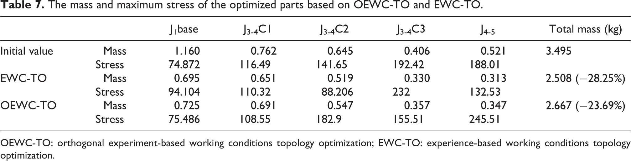
For each chosen part, once the structure of the part was redesigned, the new one would replace the original one, and then the FEA was carried out to obtain the stress of the optimized part and the end displacement of the robot. Table 7 lists the mass and maximum stress of redesigned parts based on OEWC-TO and EWC-TO, respectively. Figure 10 illustrates the trend of mass and maximum stress of the optimized parts based on both the designs, respectively. Compared with the results of EWC-TO, the total mass of the five selected parts optimized based on OEWC-TO was increased by 6.35%. While, as listed in Table 8, the end displacement of the robot optimized increased by 6.78% on average compared with the referenced design. Furthermore, as shown in Figure 11, the end displacement of the robot optimized by EWC-TO has exceeded the constraint, which did not appear in the proposed method.
The mass and maximum stress of the optimized parts based on OEWC-TO and EWC-TO.
OEWC-TO: orthogonal experiment-based working conditions topology optimization; EWC-TO: experience-based working conditions topology optimization.

The mass and maximum stress of the optimized parts based on OEWC-TO and EWC-TO. OEWC-TO: orthogonal experiment-based working conditions topology optimization; EWC-TO: experience-based working conditions topology optimization.
The end displacement of the robot optimized by OEWC-TO and EWC-TO.

OEWC-TO: orthogonal experiment-based working conditions topology optimization; EWC-TO: experience-based working conditions topology optimization.

The end displacement of the robot optimized by OEWC-TO and EWC-TO. OEWC-TO: orthogonal experiment-based working conditions topology optimization; EWC-TO: experience-based working conditions topology optimization.
Therefore, it can be concluded that the OEWC-TO can avoid the excessive mass reduction, which exists in the conventional EWC-TO, in lightweight caused by load boundary condition mismatch. And this mismatch may lead to the end displacement of the robot exceed the constraint, which could influence the effectiveness of rehabilitation and safety. Finally, based on the parts optimized by OEWC-TO, the prototype of the robot was completed as shown in Figure 12.

The prototype of 7 degree of freedom upper limb powered exoskeleton robot.
Conclusion and future work
Topology optimization is an effective method for the lightweight design of collaborative robots. In this article, a topology optimization method based on orthogonal experiments was proposed. For this method, the extreme working conditions of the robot for the FEA of parts to be optimized are determined by orthogonal experiments, which may ensure the load boundary conditions of the parts to be optimized closer to the actual maximum one. And this match could avoid the excessive material removal of the parts caused by the existing approaches of which the extreme working conditions were usually chosen based on designers’ experiences. Finally, the OEWC-TO method was compared with a referenced optimization approach (EWC-TO) to conduct the lightweight design of the 7-DOF ULPE, and the results demonstrated that the proposed approach was more reliable.
In this work, the objective and constraint condition of topology optimization were minimizing mass and the maximum end displacement, respectively. The studies about improving the reliability and effectiveness of this structure optimization method by considering more objectives (compliance, volume, etc.) and constraints (stress, natural frequency, etc.) will be carried out in the future. In addition, computational expensiveness is also a challenge to apply topology optimization techniques to the lightweight design of the collaborative robot, and we are trying to explore an effective method to improve the calculation speed. Corresponding research results will be reported after we break through these difficulties.
Footnotes
Author contribution
BL and LS contributed equally to this work and should be considered as co-first authors.
Declaration of conflicting interests
The author(s) declared no potential conflicts of interest with respect to the research, authorship, and/or publication of this article.
Funding
The author(s) disclosed receipt of the following financial support for the research, authorship, and/or publication of this article: This work was supported in part by National Key R&D Program of China (no. 2020YFC2007402, no. 2020YFC2007404, and no. 2020YFC2007400), Science and Technology Plan of Jiangsu Province (no. BE2021011, no.BE2021011-3, and no. BE2021053), and Special project of basic research on frontier leading technology in Jiangsu Province (no. BK20192004C).