
Abstract
Additive Manufacturing (AM) opens new possibilities for the production of lightweight, high-performance gears with complex internal geometries. This study proposes a novel design workflow that combines multiple software tools across computer-aided design (CAD), finite element analysis (FEA), topology optimization, lattice generation, and AM build preparation to achieve weight reduction in cylindrical gears. Two different approaches are analyzed: one based on topology optimization for removing non-critical material, and another one involving the insertion of lattice structures into the gear core. To evaluate the mechanical performance of the proposed designs in terms of stress distribution and deformation, FEA was used under representative operating conditions. To assess manufacturability, a lattice-based gear was fabricated in metal using laser power bed fusion, and a topologically optimized prototype was produced in polylactic acid (PLA) using fused filament fabrication. The results confirm that both strategies enable significant reduction in material use while maintaining suitable mechanical behavior, and validate the feasibility of manufacturing such lightweight gear designs using AM technologies. Collectively, these workflow elements deliver manufacturable, lightweight gear designs that preserve strength and structural integrity, as confirmed by simulations under operating conditions and validated through AM prototypes.
Keywords
Introduction
Mechanical devices have been created to facilitate the circular transmission of motion, power, and force from a driving element to a receptor. Belts, chains, gears, and friction wheels are among the most used devices. 1 These mechanisms help maintain a constant angular velocity ratio, ensuring efficient and accurate movement transmission between system components. 2
Although chains and transmission belts are quiet and cost-effective solutions, gears stand out as the optimal choice for many applications, owing to their versatility, compact design, fewer limitations, and ability to transmit substantial amounts of power. Furthermore, gears are standardized, meaning their dimensions and characteristics adhere to international standards, making them easy to integrate and ensuring compatibility across various industrial applications. 3
Within the vast array of gears, straight cylindrical gears are particularly notable for their simple design and efficient transfer of energy between parallel shafts. These gears play a crucial role in many industrial applications, from simple machinery to highly complex systems such as vehicles and industrial machines, offering a reliable way to transmit rotational power.
It should be noted that the design of efficient gears presents several challenges, with an important one being the need to minimize the vibrations and noise caused by gear meshing. 4 These vibrations not only affect the system’s performance but can also contribute to wear and reduce the lifespan of components. Modifying the geometry of gears can significantly alter their frequency response, influencing both the amplitude and phase of vibrations. 5
Optimization techniques are often employed to address these challenges. Such techniques can be broadly divided into two categories: shape optimization and size optimization. 6
Shape Optimization focuses on modifying the gear geometry while ensuring that the required performance standards are met. In this type of optimization, parameters such as the radii, edges, and dimensions are adjusted to achieve lighter components without compromising structural efficiency. For example, adjusting the tooth profile can reduce unnecessary contact between gears, leading to reduced vibrations and improved power transmission efficiency. 7
Size Optimization involves adjusting parameters such as the thickness or material properties. This optimization aims to reduce weight while maintaining the required strength and stiffness, and can be particularly useful in minimizing material usage without compromising gear performance. 8
Topological optimization refers to the arrangement of structural elements and their connections. In discrete structures, it involves generating or removing structural elements between existing joints and defining new connections. In continuous structures, topological optimization may involve the separation or joining of elements, which requires determining the geometry of cuts that define the new structural layout. 9
Another advancement in optimization is the development of lattice structures. These are specific material distributions that form a three-dimensional network through nodes and bars. Lattice structures offer exceptional mechanical properties, allowing for weight reduction without sacrificing rigidity and strength. These structures represent an evolution of topological optimization because they create regular cell patterns that can be adjusted to enhance component performance.6,7,9,10,11
Recent studies support the viability of this approach for AM metal gears. Tunalioglu and Torun 12 analyzed the wear behavior of 3D-printed steel spur gears and reported that surface quality and wear resistance are strongly influenced by post-processing strategies. Tezel et al. 13 compared AM gears with conventionally manufactured gears under identical conditions and concluded that, despite their slightly increased wear, AM gears can match traditional designs in terms of functionality and efficiency. Complementing these findings, Basak et al. 14 demonstrated that gears manufactured using bound metal deposition followed by machining exhibit lower wear and reduced noise emissions, particularly when printed with fine layer heights.
Expanding beyond gears, Huang et al. 15 applied topological optimization to periodic lattice structures for crash and static loading scenarios, confirming the structural efficiency and adaptability of these designs in demanding applications. Malik et al. 16 conducted a parametric evaluation of dimensional accuracy in polymer lattice gears manufactured using vat photopolymerization and material extrusion, underscoring the critical role of process parameter tuning for geometric fidelity. Collectively, these studies reinforce the potential of lattice-optimized AM components for lightweight, high-performance mechanical applications.
This paper details a training activity within a Euroregional collaboration project focused on design optimization for 3D printing at two university centers, introducing a novel design workflow that combines multiple software tools. Tecnun at University of Navarra uses Creo (PTC Inc., Boston, MA, USA) for gear parametrization and Ansys (Ansys, Inc., Canonsburg, PA, USA) for kinematic/contact and strength analyses, while the Public University of Navarra (UPNA) employs SolidWorks Simulation v2024 (Dassault Systèmes) for topology optimization.
This paper presents the analysis and optimization of straight cylindrical gears using topological optimization and lattice structures to enhance their performance. Gear mechanisms were reviewed, followed by an analysis of gear interactions using Ansys and Creo. Then, topology optimization techniques were applied in Ansys and SolidWorks Simulation v2024 to create lighter, more efficient gear designs without compromising strength. These tools integrate additive manufacturing (AM) constraints to ensure feasibility. Additionally, lattice structures were investigated to reduce material usage in 3D-printed gears without affecting mechanical properties. Collectively, these elements deliver manufacturable, lightweight gear designs that preserve strength and structural integrity, as confirmed by simulations conducted under operating conditions. The training provides both theoretical and practical knowledge, promoting the use of advanced simulation and AM tools in an international collaborative setting. Participants gain skills in innovative technologies aimed at improving mechanical performance and sustainability in industrial systems.
Case study
This study examined two spur gear cases with straight-tooth profiles, commonly used in mechanical transmissions for their efficiency and ease of manufacturing. The first case, developed at Tecnun, involves a commercially available spur gear, namely, SFA-4036 from AOKI SEIMITSU KOGYO, Kawaguchi City, Saitama Prefecture, Japan, and the use of Creo and Ansys for topological optimization to reduce weight while maintaining performance. The second case, from UPNA, involves the analysis of a custom-designed Mn5 Z50 spur gear for high-power applications. This 50-tooth gear, supplied by Engranajes Pamplona (ENPA), was optimized using SolidWorks Simulation v2024 to enhance its precision and durability. This gear, made of 316L stainless steel, underwent surface hardening to improve wear resistance. The properties of both gears are summarized in Table 1, highlighting their dimensions, materials, and applications.
Gear properties.
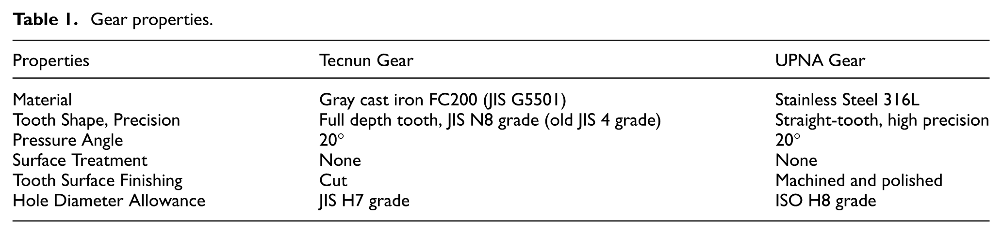
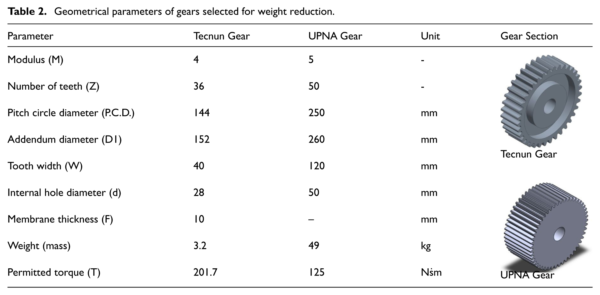
Table 2 summarizes and compares the key design parameters of two spur gears, one developed at Tecnun and the other at UPNA. Each row lists a specific parameter, with the corresponding values for the Tecnun Gear and UPNA Gear provided side by side. The “Unit” column indicates the measurement unit used. The table is organized by the relevant sections of the gear. The parameters include the modulus, number of teeth, pitch circle diameter, addendum diameter, tooth width, internal hole diameter, membrane thickness, weight, and permitted torque. Notably, some parameters, such as the membrane thickness for the UPNA Gear, are not applicable or were not provided.
Geometrical parameters of gears selected for weight reduction.
Methodology for gear optimization
Optimization approach for Tecnun Gear
The optimization process began with the creation of a 3D model of the gear in Ansys Workbench. The baseline design was derived from conventional gear geometry with consideration to standard mechanical requirements. The model was imported into the finite element analysis (FEA) environment, where the material properties, boundary conditions, and loads were defined. To ensure accurate results, a high-quality mesh was created as follows: the gear was discretized using tetrahedral and hexahedral elements, with a refined mesh in regions expected to undergo high stress concentrations. Adaptive meshing was employed to optimize computational efficiency while maintaining accuracy. Convergence studies were performed to ensure that the mesh density could provide reliable results without excessive computational cost. To reduce the gear weight while maintaining structural integrity and performance under operating loads, topology optimization was conducted using the built-in Ansys Workbench tools. The optimization process consisted of the following steps:
(1) Definition of design space: The full volume of the gear was initially considered as the design space. Constraints were set to preserve critical functional features such as the hub, tooth profiles, and key interfaces.
(2) Load and boundary conditions: Operational loads, including torque and tangential forces, were applied. The boundary conditions ensured realistic constraints, simulating the gear’s interaction with its mating components.
(3) Objective function: The primary objective was mass reduction while ensuring that stress levels remain within allowable limits. A compliance-based objective function was employed to optimize stiffness.
(4) Manufacturing constraints: Constraints such as symmetry and minimum feature size were imposed to ensure manufacturability using conventional or AM techniques.
(5) Optimization execution: The solver iteratively removed low-stress material, refining the topology. This resulted in an optimized material distribution, highlighting non-essential regions.
(6) Post-processing: The optimized shape was analyzed to verify its mechanical performance. The stress distributions, factor of safety, and deformation levels were evaluated to confirm compliance with the design criteria.
In Creo, the reconstruction and refinement of computer-aided design (CAD) involved the process of creating and improving 3D models using advanced tools and techniques within the software. The process involved the following steps:
(1) Importing optimization results: The Ansys-generated topology was used as a reference to create a parametric model.
(2) Geometry refinement: The optimized structure was manually refined to remove irregularities and ensure manufacturability. Smooth transitions and rounded edges were introduced to improve structural performance.
(3) Feature definition: Standard engineering features such as fillets, ribs, and reinforcements were added to enhance durability and manufacturability.
(4) Parametric modelling: A fully parametric model was created, allowing for future design modifications and iterative improvements.
(5) Validation analysis: The refined model underwent a final FEA to confirm that the performance targets can be achieved under the specified operating conditions.
This methodology ensures that the optimized gear design can balance weight reduction with mechanical robustness, making it suitable for real-world applications while maintaining manufacturability within industrial constraints.
Optimization approach for UPNA Gear
The methodology followed at UPNA involved several key steps to fabricate the first prototype using polylactic acid (PLA) and observe the final geometry of the design. The process began with the creation of the initial 3D model, followed by its optimization using topology optimization in SolidWorks, and the fabrication of the final prototype.
(1) Initial design: The first step involved designing the 3D model of the component, which could either be an entirely new design or an existing piece subject to optimization. In this case, the existing model was selected for optimization, aiming to reduce material usage without compromising functionality.
(2) Topology optimization in SolidWorks: The model was imported into SolidWorks, where optimization was carried out. This stage consisted of the following steps:
Defining material properties: The material to be used for the component was specified. Setting boundary conditions: Critical areas that needed to remain unchanged were defined, along with the loads and constraints to be applied. Refining the mesh: A mesh was generated to divide the model into finite elements. The mesh quality and density were adjusted to balance accuracy with processing time. Choosing optimization objectives: The main objective was to minimize material usage while achieving the required strength and performance. Running the topology optimization simulation: SolidWorks applied FEA principles internally to remove material iteratively from non-critical areas, optimizing material distribution and refining the design through multiple iterations. Evaluation of results: The optimization results were analyzed, and adjustments were made to highlight key stress areas that are critical to component functionality. Exporting the optimized model: The final optimized geometry was exported in STL format for the next step in the workflow.
(3) Slicing in UltiMaker Cura: The optimized model was imported into the UltiMaker Cura software, where several print settings were configured:
Printer selection: The Prusa i3 MK3S+ printer was selected for printing. Configuring print settings: Settings such as the layer height, infill density (set to 100% in this study), and print speed were configured based on project requirements. Generating supports: Supports for overhangs or complex geometries were generated automatically by Cura as needed. Slicing the model: Cura processed the model and generated the corresponding G-code file, which directed the printer to construct the model layer by layer.
(4) 3D printing: The G-code was transferred to the Prusa i3 MK3S+ printer using an SD card. The printing process began after confirming that the PLA filament was loaded and properly set up. The printing process was closely monitored to ensure the correct adhesion of the first layers and maintain printing quality throughout the process.
(5) Post-processing and evaluation: Once the prototype was printed, the final geometry was assessed for accuracy, structural integrity, and adherence to design specifications. The PLA material, selected for its ease of use, low warping properties, and biodegradability, enabled quick prototype fabrication. This step validated the effectiveness of the optimized design and served as a demonstration of geometrical feasibility before considering further manufacturing steps.
This methodology, from initial design through topology optimization and fabrication, ensured the creation of a functional prototype that met the desired specifications while minimizing material usage and production cost.
Gear optimization objective function
The gear body was optimized through a solid isotropic material with penalization-based density formulation that minimized structural compliance, with objective
Here
In the SolidWorks workflow, the built-in “maximize stiffness-to-weight ratio” option was selected, combined with a target of 30% mass reduction. Boundary conditions were set to preserve the bore and keyway, and a distributed normal load of 1000 N was applied on each of the 50 tooth flanks, delivering a torque of 125 N·m at a pitch diameter of 250 mm.
Results
Tecnun Gear optimization results
The topological optimization of the Tecnun Gear aimed to reduce the gear’s weight while preserving its structural integrity and functionality. This process involved dividing the gear into three sections, namely, the teeth area, shaft area, and central ring, and applying specific constraints to ensure that material reduction did not compromise performance. Figure 1 illustrates the various stages and methodologies involved in the gear’s topological optimization, focusing on reducing weight while maintaining structural integrity. A central element of this process is the application of a cyclic repetition design constraint, as shown in Figure 1(a). This constraint ensures that material removal follows a cyclic pattern around the gear’s axis, which is essential to create a balanced gear capable of withstanding operational stresses evenly across its structure. By maintaining symmetry and uniformity, the optimized design retains its functionality despite material reduction.

Topological optimization of gear structures. a) Application of cyclic repetition design constraint in optimization software, ensuring uniform material removal around the gear axis to maintain structural balance. b) Optimized gear designs with varying mass retention percentages (50%, 40%, 30%, 20%, and 15%), illustrating progressive material reduction and impact on structural integrity. c) Lattice structure patterns (triangular, square, and hexagonal) integrated into gear’s central ring, demonstrating innovative approaches for further weight reduction while preserving strength and functionality.
Building on this foundation, Figure 1(b) presents the outcomes of the optimization process with varying levels of mass retention, ranging from 50% to 15%. Each design progressively reduced material, with strategic cut-outs aimed at minimizing weight without compromising structural integrity. These visualizations are crucial for understanding how the gear’s structure evolved as mass was reduced and for identifying the threshold at which structural integrity began to degrade. The images show that, while significant mass reduction was achieved with minimal impact on performance down to 20% mass retention, further reduction to 15% led to excessive deformation and stress, indicating a practical limit to mass reduction.
Complementing these approaches, Figure 1(c) shows the integration of lattice structures into the gear’s central ring, featuring patterns such as triangular, square, and hexagonal lattices. These innovative designs aimed to achieve additional weight reduction without sacrificing strength. Lattice structures offer a novel approach to material optimization in mechanical design, demonstrating how advanced engineering techniques can enhance efficiency. By strategically incorporating these patterns, the gear’s performance is maintained, even as its weight is significantly reduced.
Mass variation analysis (Figures 2 and 3) revealed that both optimization approaches effectively reduced the gear’s weight. Furthermore, the moments of inertia were analyzed to understand the gear’s resistance to rotational forces. The moments of inertia decreased with mass, indicating reduced resistance to rotation.

Variation of moments of inertia with respect to mass of topology-optimized gears.

Variation of moments of inertia with respect to mass of lattice-optimized gears.
Optimizing the central part of the gear (Figure 2) reduced the mass from 3.45 kg (solid gear) to 3.26 kg (5.51% reduction), and the mass moment of inertia from 9546.8 kg·mm2 to 8985.1 kg·mm2 (5.88% reduction). Figure 3 shows five lattice types: two beam-based lattices with hexagonal and octagonal cell types, and three sheet-based lattices with square, hexagonal, and triangular cell shapes. All lattice structures had a cell size of 10 mm. Beam-based lattices employed circular beams with a diameter of 1.5 mm, while sheet-based lattices used walls with a thickness of 1 mm. Figure 5 shows that, for the cell types and parameters used to define the lattice structures, the mass and mass moment of inertia reductions are similar across the considered lightweight gears. Using these lattice structures in the central region reduced the average mass to approximately 3.06 kg (reduction of 11.3% compared with solid gear), and the mass moment of inertia to 8540.5 kg·mm2 (reduction of 10.5% compared with solid gear).
The topology-optimized shapes were analyzed to assess the mechanical performance. The refined model underwent a final FEA to confirm that the performance targets were achieved under the specified operating conditions. The stress distributions, strain, and deformation were evaluated to confirm compliance with the design criteria. Figure 4 shows the finite-element mesh of the topology-optimized gear, with targeted refinement along the tooth flanks and multiple element layers across the contact width. The model employed second-order 20-node hexahedral (HEX20) and 15-node wedge (WED15) solid elements to accurately capture the curvature, relevant stress, and bending at the tooth root. For the lightweight gear with 15% retained mass, the finite-element model comprised approximately 72,000 elements. For load definition, a pressure angle of 20° and torque of 201.7 N·m applied at a pitch diameter of 144 mm were considered, with a tangential force of 2801.4 N.

Mesh view of topology-optimized gear showing targeted refinement along tooth flanks and multiple layers across contact width, using second-order 20-node hexahedral and 15-node wedge solid elements.
Figure 5(a) and (b) shows the von Mises equivalent stress distribution in the topology-optimized gears with (a) 50% retained mass and (b) 20% retained mass. For the 50% retained-mass gear, the maximum von Mises stress occurred in the tooth (Figure 5(a)). A comparison of the stress distributions revealed that the design with 20% reduction in weight transfers the maximum stress from the gear teeth to the central ring, indicating potential structural issues (Figure 5(b)). This effect becomes more pronounced as the retained mass decreases.

Von-Mises equivalent stress distribution in topology-optimized gear with (a) 50% retained mass and (b) 20% retained mass. Variation of (c) equivalent (von-Mises) stress, (d) strain, and (e) deformation as function of total mass percentage.
Figure 5(c) to (e) shows the variation in the von Mises equivalent stress, strain, and total deformation as a function of the retained-mass percentage for the lightweight gear designs. The trends show a slight increase in stress and strain (Figure 5(c) and (d)) as the retained mass decreases, with acceptable levels maintained down to 20% retained mass. At 15% retained mass, there is a significant increase in the maximum von Mises equivalent stress and strain. In contrast, deformation (Figure 5(e)) increases gradually as the retained mass decreases. Accordingly, the structural performance assessments indicate that the topology-optimized gears maintained their integrity at and above this 20% threshold.
UPNA Gear optimization results
The topological optimization of the Mn5 Z50 gear conducted at UPNA led to significant weight reduction, achieving a decrease of 51% without compromising functionality. This process played a crucial role in enhancing the component’s efficiency by reducing the amount of material used and, consequently, the manufacturing costs. The optimization was carried out in SolidWorks, applying specific constraints to critical areas of the gear, such as the tooth surface and rotation axis, to ensure structural integrity.
Figure 6 shows the process and results of the topological optimization of the Mn5 Z50 gear conducted at UPNA. Figure 6(a) shows the initial design phase in SolidWorks, where specific constraints were applied to the gear’s critical areas to ensure structural integrity during optimization. Figure 6(b) shows the optimized gear design, which achieved significant reduction in material usage while preserving functionality and structural soundness. Figure 6(c) shows a close-up view of the optimized gear, emphasizing areas where material was strategically removed to achieve weight reduction without compromising performance. The final optimized gear design, shown in Figure 6(d), complete with annotations that highlight the weight reduction of 51%, was validated by 3D printing a PLA replica to enable further experimental studies and mechanical validation. Notably, PLA was selected as the replica material because of its widespread use, low cost, and excellent printability, which make it particularly suitable for rapid prototyping and the early validation of complex geometries.

Topological Optimization of Mn5 Z50 Gear. a) Initial gear design in SolidWorks with constraints applied to critical areas such as the tooth surface and rotation axis. b) Optimized gear design exhibiting material reduction while maintaining structural integrity. c) Detailed view of optimized gear, highlighting reduced material in critical areas. d) Final optimized gear design with annotations indicating weight reduction and structural validation through 3D printing in PLA.
The initial analysis faced computational challenges owing to the gear’s size and complex mesh. To overcome this, the studies began with a single tooth, progressing to groups of five teeth, a quarter of the gear, and finally the entire component. This approach elucidated the gear’s behavior under contact forces and allowed for progressive optimization. Post-optimization, the gear’s weight in 316L stainless steel was reduced by 51% while maintaining structural integrity. A 3D-printed PLA replica weighing 1.80 kg was created for validation, enabling experimental studies without expensive materials. This process significantly improved design efficiency and manufacturing sustainability. The topological optimization and lattice integration strategies employed in this study align with previous research that has achieved significant weight reductions in gear components without compromising structural integrity. For example, a previous study on spur gears using honeycomb lattice structures achieved a 19% volume reduction while maintaining stress and displacement comparable to those of solid gears. 17 Similarly, the use of parameter and structural optimization has been shown to reduce the moment of inertia in heavy-duty gear drives by over 30%, validating the efficacy of combined optimization approaches. 18
Additive manufacturing of lightweight gear integrating strut-based lattice structures
To analyze the feasibility of manufacturing gears with a lattice structure in their core, a M3Z20 spur gear supplied by ENPA was considered. The weight of the spur gear was reduced using a strut-based lattice structure. The lattice employed a square cell shape with a 5-mm cell size and combined outer horizontal beams, outer vertical beams, and angular beams (Figure 7(a)). All beams feature a circular cross-section with a diameter of 0.9 mm. Compared with the solid gear, which has a mass of 5.56 kg and mass moment of inertia of 293.87 kg·mm2, the designed lightweight gear, with a mass of 2.28 kg and mass moment of inertia of 176.51 kg·mm2, achieves mass reduction of approximately 59% and mass moment of inertia reduction of approximately 40%, which can lower rotational energy requirements and improve acceleration. Several lightweight spur gear samples with a lattice structure were manufactured via Powder Bed Fusion–Laser Based/Metal (PBF-LB/M) using 316L stainless steel on a RenAM 500 Machine. The main manufacturing parameters are listed in Table 3.
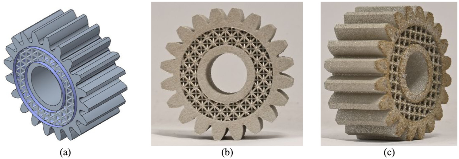
SS316L gear with strut-based lattice structure, fabricated using AM: (a) lightweight gear design with lattice structure; (b) front view and (c) side view of manufactured gear.
AM parameters employed for gear manufacturing.

AM: Additive manufacturing.
Figure 7(b) and (c) shows images of a metal gear manufactured via PBF-LB/M, demonstrating the feasibility of the proposed design. Figure 7(c) shows the rough surface finish that resulted from the removal of the support structure.
Beyond visual inspection and dimensional validation, the present study did not include mechanical characterization of the fabricated components. While this study focused on the design, topological optimization, and manufacturability of lattice-integrated gears, the experimental evaluation of mechanical properties, such as stiffness, strength, and failure modes, remains a key direction of future work, and is particularly important for assessing the structural performance of printed parts under realistic service conditions. This is particularly relevant, as previous studies have shown that integrating lattice structures into gear bodies enhances vibration damping and reduces noise levels, with experimental results indicating superior performance compared with solid gear counterparts. 19 Moreover, finite element method analyses have confirmed that lattice-based gear bodies can sustain comparable load-carrying capacities while achieving substantial mass reductions, thereby reinforcing the validity of the design strategies employed in this study.17,20
Conclusion
This paper presents an educational exploration of spur gear optimization at Tecnun at the University of Navarra and UPNA. Using advanced CAD software and topological optimization, significant weight reduction was achieved without compromising performance. The work with Creo and Ansys at Tecnun demonstrates effective optimization for commercial gears, while analysis using SolidWorks Simulation v2024 at UPNA highlights precision and durability in high-power applications. The integration of lattice structures with AM reduces material use and advances sustainable design. This activity equips students with skills in advanced simulation and manufacturing, fostering innovation and efficiency in engineering education. The findings provide a strong foundation for future advancements in mechanical design and sustainability.
Although the proposed designs exhibited structural integrity under static loading and were successfully manufactured with lattice-integrated features, fatigue testing has not yet been conducted. Future work will address this limitation by experimentally assessing the durability of AM gears under cyclic loading and characterizing the mechanical behavior of the printed SS316L. These efforts will improve model fidelity and validate the long-term performance of AM gears.
Footnotes
Handling Editor: Yuansheng Zhou
Funding
The authors disclosed receipt of the following financial support for the research, authorship, and/or publication of this article: This research was supported by Grant PLEC2024-011165 funded by MICIU/AEI/ 10.13039/501100011033. Additional support was received from “ERDF – A way of making Europe” by “ERDF/EU”. This study was also supported as part of the ADDILANZA and MMAM projects by the Euroregion Nouvelle-Aquitaine Euskadi Navarra under the “Euroregional Innovation” program.
Declaration of conflicting interests
The authors declared no potential conflicts of interest with respect to the research, authorship, and/or publication of this article.
Data availability statement
The datasets generated during and/or analyzed during the current study are available from the corresponding author on reasonable request.