
Abstract
In this article, the problem of video inpainting combines multiview spatial information and interframe information between video sequences. A vision system is an important way for autonomous vehicles to obtain information about the external environment. Loss or distortion of visual images caused by camera damage or pollution seriously makes an impact on the vision system ability to correctly perceive and understand the external environment. In this article, we solve the problem of image restoration by combining the optical flow information between frames in the video with the spatial information from multiple perspectives. To solve the problems of noise in the single-frame images of video frames, we propose a complete two-stage video repair method. We combine the spatial information of images from different perspectives and the optical flow information of the video sequence to assist and constrain the repair of damaged images in the video. This method combines the interframe information of the front and rear image frames with the multiview image information in the video and performs video repair based on optical flow and a conditional generation adversarial network. This method regards video inpainting as a pixel propagation problem, uses the interframe information in the video for video inpainting, and introduces multiview information to assist the repair based on a conditional generative adversarial network. This method was trained and tested in Zurich using a data set recorded by a pair of cameras mounted on a mobile platform.
Introduction
With the development of deep learning and computer vision technology, multiview vision system has become significant in the field of automation. 1,2 Due to the abundant image information provided by the multiview system, the multiview image acquisition system is widely used in navigation, 3 panorama, 4 the occlusion process and vehicle classification, 5 target detection, 6 –8 and tracking. 9,10,26 As shown in Figure 1, multiview vision target recognition and positioning is used for assisted driving systems, and multiview vision systems are also used for obtaining surround views around the car body. At present, the basis of autonomous driving is that the vehicle autonomously completes environmental perception, positioning, and mapping. In order to ensure the robustness and reliability of the system, most tasks require high sensor redundancy. Therefore, automatic driving systems generally use a variety of onboard sensors. Hardware modules can be roughly divided into five categories: exteroceptive sensors, proprioceptive sensors that monitor the state of the vehicle itself, communication units, actuators, and computing units. For positioning and mapping, the currently widely used methods are GPS-IMU fusion, SLAM, positioning based on prior maps, and so on. Perceiving the surrounding environment and extracting information for safe navigation is one of the cores of autonomous driving. And with the development of computer vision research in recent years, cameras including three-dimensional vision have gradually become the most commonly used sensors in perception. The main algorithms are image-based target detection, semantic segmentation, three-dimensional target detection, road and lane line detection, target tracking, and so on. In a word, in terms of environment perception and positioning and mapping, it is mainly through the fusion of information collected by various sensors such as cameras, lasers, and radars to achieve autonomous navigation and control of vehicles. Therefore, the interference or loss of video image signals throughout the method of signal acquisition, compression, translation, and decompression can have an effect on the system’s ability of perceiving the encompassing atmosphere. The aim of video inpainting is to fill the missing areas with content that is consistent in space and time for a given video sequence. This technology 11 –13 has been widely used in the field of autonomous driving.
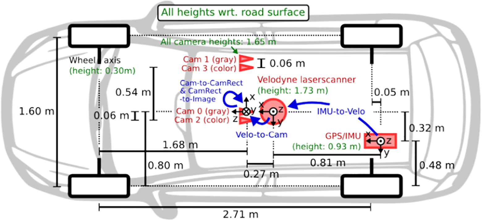
A self-driving vehicle with four cameras cam0-3.
Due to the motion of video image capture equipment and the complex movement of objects in the video, inpainting real-world HD video sequences is still challenging. Most existing video inpainting algorithms can be classified into two categories. The first follows the normal image inpainting pipeline that describes drawback as a patch-based improvement problem, which inpaints missing regions by sampling spacial or spatial-temporal patches of the well-known regions. Although some good results have been achieved, these methods have two disadvantages. First, these methods fill the missing regions by forward a sleek and homogeneous motion field within the missing region. Therefore, they cannot complete the repair of videos with complex motions. Second, these methods are mainly based on the idea of mathematical optimization. The optimization-based method has high computational time complexity and cannot meet the requirements of real-time processing. Recently, the method of video image restoration supported by deep learning 4,14 uses associate degree autoencoder to find out the content and linguistics expression of the scene, combined with the generative adversarial network (GAN) to perform video image restoration. The network trains the reconstruction loss of the autoencoder and the adversarial loss of the GAN and reconstructs a good image from the damaged image.
Autoencoder is an unsupervised neural network model. It can learn the hidden features of the input data, which is called encoding. At the same time, the learned new features can be used to reconstruct the original input data, which is called decoding. Autoencoder
15,16
performs feature extraction on the image to obtain a feature vector and reconstructs the high-dimensional image from the low-dimensional vector, which tries to obtain high-level semantic features of the scene. Pathak et al.
4
pioneeredly proposed an approach that combines the reconstruction loss of the autoencoder and generate the data learned by the adversarial loss to solve the problem of video image restoration. As shown in Figure 2(a), an encoder is employed because of the generator (G) of the GAN. The broken image (

Schematic diagram of different repair methods. (a) Context-encoder method diagram, (b) image-to-image method diagram, and (c) conditional generation adversarial networks method diagram.

Qualitative comparison of different image restoration methods. (a) Left camera destroyed image, (b) right camera nondestroyed image, (c) left camera inpainting target, (d) PatchMatch result, (e) image-to-image result, and (f) our result.
Although convolutional neural networks (CNNs) and GAN have significant effects in image restoration, 21 video restoration through deep learning methods is still a challenge. Even if the above methods are applied to the video inpainting process, it is difficult to merge the interframe information of the video sequence with the spatial information of the single-frame image. Using deep learning-based image inpainting methods to solve a series of problems in the video field is still challenging. On the one hand, an immediate application of a picture inpainting algorithmic rule to every frame of a video sequence separately cannot make full use of the information on time series. On the other hand, due to the large number of single-frame images of a video sequence, it is difficult to ensure consistency in timing when the entire video sequence is input into the CNN at one time. Furthermore, directly repairing the entire video sequence requires a large amount of graphics storage to store the subsequent processing operations of video image frames and video image processing result, which is computationally impractical.
Xu et al. 22 proposed a video inpainting method guided by optical flow. In this method, the interframe information in the video sequence is expressed in the form of optical flow, and the damaged optical flow is repaired instead of restoring original single-frame images in the video sequence. Compared with the original image method, using this method to complete the restoration of missing optical flow is easier than directly filling the actual pixels of an image. Making use of optical flow to propagate the pixels can maintain natural consistency in timing, which makes better use of the video sequence. Since the background and most object motions in the video are traceable, the pixel motion of the image is easy to obtain. This method can reduce the difficulty of video restoration by synthesizing a cross-frame optical field. Most of the pixels in the missing area can be made up by spreading from the visible area. This method can make full use of the interframe information of the images in the video sequence, and it is far easier to repair the single-frame image in the video sequence through the refinement of the optical flow field. However, for binocular systems, it is difficult to fuse multiview information. In addition, it is difficult to repair objects that are completely damaged in the video sequence.
We propose a video inpainting method that combines optical flow guidance and multiview scene. This method combines the consistency of the video sequence in the timing and the image information in the space of the multicamera system to perform video inpainting. The solution in this article is divided into two stages. The purpose of the first stage is to fuse the image information of the perspective that need to be inpainted and auxiliary perspective in the current multiview system and obtaining the preliminary restoration result of the image frames in the video sequence, which reduces the additional cost of the subsequent optical flow guidance inpainting process and makes full use of the multiview image information. The second stage utilizes the initial inpainting results from the first part to extract the optical flow of the video sequence and completes the refinement and inpainting process of the optical flow field from coarse to fine through the deep convolutional network. Finally, we can take advantage of the optical flow to propagate the pixels of visible areas. The innovations of the method in this article are as follows: A video inpainting method based on optical flow guidance and a multiview scene is proposed, which combines the timing information of video sequences and the spatial information of a multiview scene for video inpainting and explores new methods in the field of video inpainting. Due to the angle deviation of the multiview system, the spatial transformation network (STN) is introduced to complete the spatial alignment of the multiview images and better integrate the spatial information of the multiview image. A deep optical flow repair network is introduced, which can maintain time consistency for processing missing areas of arbitrary shapes and complex movements.
The whole method combines the temporal information of the video sequence and the spatial information of the multiview scene. Damaged image frames in a single-view video sequence can get accurate and clear results by this method that fuses spatial transformation, group convolution and features channel information exchange.
Proposed algorithm
This article proposes an efficient video inpainting method to deal with video signal abnormalities and damage resulting from the process of signal acquisition, compression, transmission, and decompression. This method utilizes the prior information provided by the multiview scene combined with the interframe information of the images in the video sequence to complete the restoration of the video sequence. Figure 4 describes the overall architecture of our video inpainting method. The approach consists of three steps. The first step aims to complete the inpainting of the damaged image frame from another view with the CGAN which introduces an STN, thus obtaining the preliminary repair result. The second step aims to complete a coarse-to-fine flow inpainting which is extracted from the preliminary repair result. Finally, the third step is to complete the pixel propagation guided by the optical flow to achieve the final repair result.
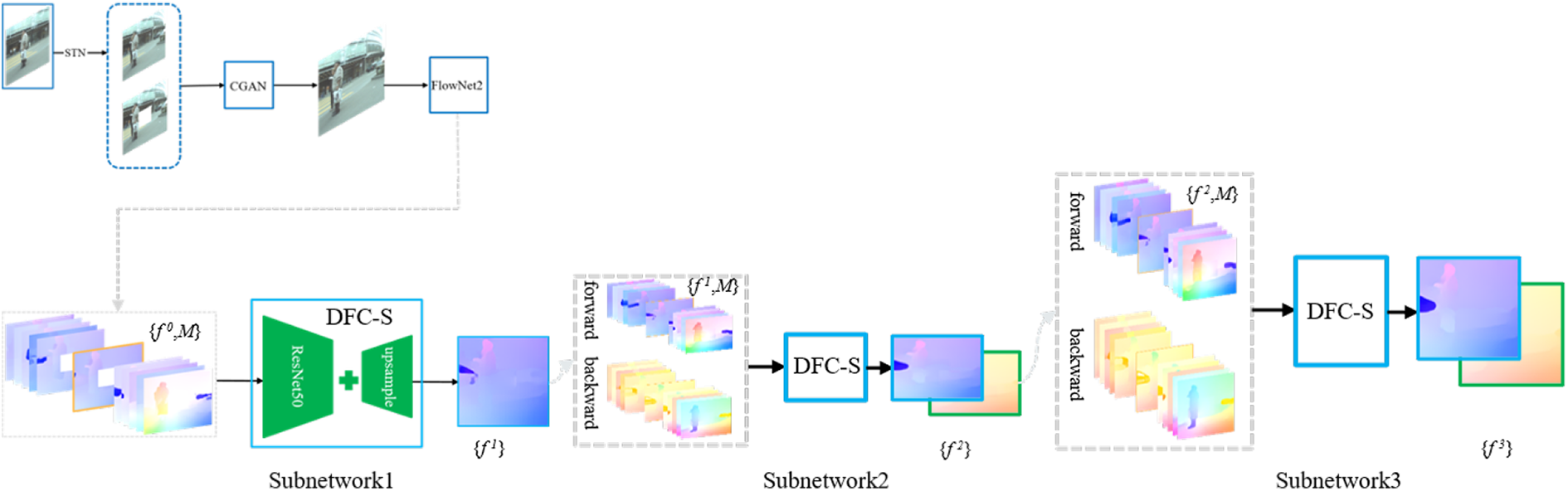
The pipeline of our video inpainting approach based on optical flow and multiview scene.
The CGAN of the primary step may be a structure composed of a generator and a discriminator, which is employed to be told the linguistics info and have distribution of image frames during a single-view video sequence. The data set we used consists of eight consecutive time series from two perspectives. The first step which integrates multiview scenes is to combine the damaged video image frames taken by the left camera and the intact right camera video image frames for preliminary restoration. The damaged left-view image frame and the right-view image frame which is aligned through the STNs are input in the generator. In the decoding part, the generator reconstructs the restored left-view image frame. The options of the discriminator are to verify whether or not the image frame input to the discriminator is that the generated distribution or the real distribution, resulting in generator generates a more realistic repaired image frame. In the encoder, we respectively perform feature extraction on the left-view damaged image frame and the spatially transformed right-view image frame through convolution. After convolution, we perform half-channel analysis on the feature maps extracted from the two perspective image frames, integrating the information of the two perspective image frames adequately. Since the images in the video sequence are partially damaged, a partial feature map of the encoder is additional to the decoder to scale back the loss of data within the uninjured space. In this way, the network focuses on the damaged area during the training process.
Encoder–decoder
The generator of the conditional generation adversarial network within the initiative is a straightforward encoder–decoder design. This architecture reconstructs the image after encoding the image into high-dimensional features. The image content and semantic information is learned through the generator.
15
–17
The context encoder
4
first combines the autoencoder with GAN for image generation. The image-to-image method
14
uses L
1 distance to constrain the gap between the generated image and the real image. However, the image-to-image method only encodes and reconstructs the damaged image to get the repaired image.
27
Because of the lack of prior information, this method cannot get a true and clear repaired image. The conditional generation adversarial network in this article introduces image frames (y) from the intact right-view video sequence to assist and constrain the repair of damaged image frames (

where x is the inpainting target of the left-view image,
Spatial transform network
Since the multicamera system has a certain angle in space, spatial alignment is achieved in the damaged area between the two perspectives. Before inputting the right-view intact image frame into the generator, it undergoes spatial transformation through the STN. A spatial transform network is a module planned by Jaderberg et al. 23 to boost the hardiness of neural networks. By introducing an STN, the network will mechanically align the pictures from totally different views in space, so that the network can better integrate spatial information from different perspectives. 25 In our work, the STN performs spatial transformation preprocessing on the proper perspective image to eliminate the sector of read deviation between the left and right views. Figure 5 describes the structure of the spatial transform network.

The structure of the spatial transform network.
The right-view image passes through the STN, and the network outputs six affine transformation parameters (

where

However, the pixel coordinates after the inverse transformation may be floating point data. We should use the neighborhood knowledge of the initial image knowledge for interpolation. Bilinear interpolation is employed here. Figure 6 shows that a floating purpose coordinate is found within the middle of four constituent coordinates.
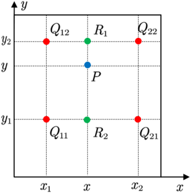
Bilinear interpolation schematic.
Conditional generative adversarial networks
Context encoder combines autoencoder and generative adversarial loss for image restoration. As shown in Figure 1(a), it rebuilds and repairs broken images (
By introducing conditional input to constrain the image generation process, it takes the damaged image (
Image-to-image solves these problems by introducing conditional input to constrain the image generation process. As shown in Figure 1(b), it takes the broken image (
In our method, GAN loss can be described as

where G tries to minimize this objective against an adversarial D that tries to maximize it

Previous work 4,14,24 tested that the mixture of reconstruction loss and adversarial loss will improve the smoothness of the generated image. This part utilizes image frames of multiple scenes, combined with reconstruction loss and counter loss to jointly train the network for multitask learning.
The final optimization goal is

where
Deep convolution optical flow repair subnetwork (DFC-S)
The second stage is to make full use of the interframe information about the image frames in the single-view video sequence to repair the damaged image frames. In order to avoid the degree of complicated calculation caused by directly filling the image pixels, the method proposed in the second step is to refine and repair the optical flow of the video sequence composed of the initial repaired image in the first step, and further spread through the optical flow to guide the video images between sequences are repaired. Figure 2 describes the main architecture of single-view video repair guided by optical flow. It mainly includes two parts. The first part completes the repair of the missing optical flow. Additionally, the second part completes the repair of the images in the video sequence under the guidance of the optical flow field.
In the first part, an optical flow refinement network (DFC-Net) from coarse to fine is mainly introduced. DFC-Net consists of three similar subnetworks (DFC-S). The first subnetwork estimates the optical flow at a relatively rough scale, and inputs the optical flow output by the first subnetwork into the second and third subnetworks for further refinement. In the second part, the propagation is guided by the optical flow from different frames, and the pixels in the damaged area are filled by the pixels in the known area. The theory of the second step method is as follows.
The inputs of the first subnetwork are the spliced tensor in the channel dimension of the optical flow map from consecutive frames of the video sequence and the binary mask image associated with each frame image. Each binary mask image represents an optical flow in the real area of the figure. The output of the network is the optical flow of the intermediate frame of the input optical flow.
Specifically, supposing
Optical flow refinement repair network (DFC-Net)
Figure 4 shows the overall structure of DFC-Net, which is stacked through three subnetworks (DFC-S). Generally, the smaller the actual part of the optical flow, the easier it is to repair the lost optical flow. Therefore, in the first subnetwork, the shape of the optical flow graph is reduced to obtain a good initial repair effect. Then, in the second and third subnetworks, the size of each input optical flow diagram is gradually enlarged to gradually complete the restoration from coarse to fine. Compared with the scale of the original image, the input sizes of the three subnetworks are 1/2, 2/3, and 1 of the original image, respectively.
The optical flow obtained by the first subnetwork is relatively rough repaired, and the second subnetwork focuses on the repair of the details of the optical flow. To better refine the optical flow, the second subnetwork will forward the optical flow, and it is combined with backward optical flow to complete the optical flow refinement and repair together. Supposing f
1 is the coarse optical flow generated by the first subnetwork. For each continuous image frame in the video sequence (ith frame and (
Finally, the output of the second subnetwork is amplified in scale and input to the third subnetwork, which strictly follows the same procedure as the second subnetwork to obtain the final results. The visualization is provided in Figure 7, which shows that the process of the flow field is gradually improved through the coarse-to-fine refinement.
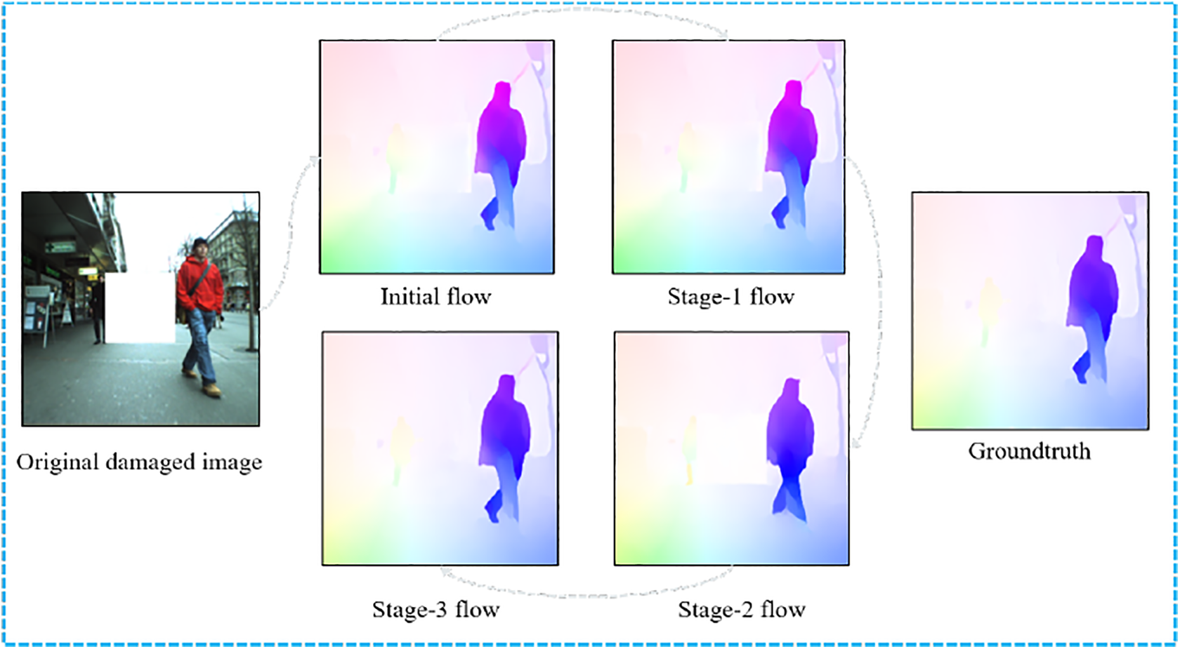
Visualization of different subnetworks outputs.
In the training process, the missing regions are randomly generated for each video sequence to train the three subnetworks. The goal of optimization is to minimize the distance between the predicted optical flow and the true optical flow. Specifically, the loss of each subnetwork is defined as

where
Flow-guided frame inpainting
The optical flow repaired by the optical flow repair network establishes the motion relationship between the pixels between the frames of the video sequence, and the propagation of the pixels can be carried out under the guidance of the optical flow. Figure 2(b) illustrates the repair process guided by optical flow.
Since the optical flow of some video frames predicted by the network has certain errors, the validity of the optical flow needs to be checked first. For a forward flow
Experiments
The GTX 2080Ti GPU was used for training and evaluation. GTX 2080Ti has 4352 cuda cores with a base frequency 1350 MHz and a boost frequency 1545 MHz. The PC has Intel i7-7800X CPU with 3.5 GHz and 32 GB of RAM. Ubuntu 16.04 for OS and PyTorch for deep learning framework were used. In order to evaluate our proposed method intuitively and quantitatively, we compare the previous methods PatchMatch, 20 context encoder, 4 and image-to-image. 14 To verify the effectiveness of video image frame restoration, an ablation experiment was carried out. The influence of various factors on the repair effect was analyzed. Figure 8 shows the repair effects of different repair methods. As shown in Figure 8(f), PatchMatch fills the space to be repaired with pixels around the broken area. When the target to be repaired is totally settled within the broken space and has completely different characteristics from the encompassing pixels, the repair cannot be completed. For example, the elongated tube in Figure 8(f) cannot be repaired by the repair technique. There are artifacts on the results repaired by the context encoder and pix2pix.

Compare different image inpainting methods. (a) Left camera damaged image, (b) right camera intact image, (c) left camera inpainting target, (d) spatial transform image, (e) our method inpainting result, (f) PatchMatch result, (g) context-encoder result, (h) image-to-image result, (i) our method without flow module, (j) our method without STN, (k) our method without GAN loss, and (l) our method without L 1 loss.
These two repair ways solely deem the linguistics data learned by the autoencoder from the scene and the information distribution generated by the GAN. The generation process of the repair results is difficult to control. Pix2pix’s method provides better results. Because jump connections are added to the pix2pix generator, there are more detailed features in the generated image. It is tough to reconstruct complete pictures and details solely by hoping on linguistics options. By introducing info from alternative views, there square measure a lot of constraints and steerage within the image generation method. Figure 8(e) shows the repair effect of this module. When the reconstruction loss is removed, the generation method of the multiview module is additional random and chaotic (Figure 8(l)). Additionally, if the adversarial loss is removed, the inpainting result shows a smoothing effect (Figure 8(e)). Finally, if the optical flow is removed, the inpainting result would be better than the results for other methods.
In order to quantitatively analyze the methods proposed in this article, we compared the previous methods from the three aspects of L 1 distance, L 2 distance, and peak signal-to-noise ratio (PSNR).
Where, the typical L 1 Loss is that the definite quantity of the typical constituent value distinction between the inpainted image and also the target image

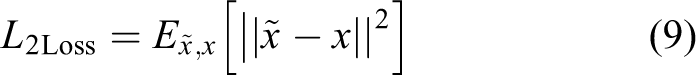
L 2 Loss is the square of the distinction between the typical pixel worth of the inpainted image and also the target image
Peak Signal to Noise Ratio (PSNR) is a standard used to measure the image distortion or noise levels. The unit is decibel, which is outlined as follows

Shows the quantitative results of the experiment. Our method shows good repair effects on L 1 loss, L 2 loss, and PSNR.
Table 1 shows the quantitative results of the experiment. Our method shows good repair effects on L 1 loss, L 2 loss, and PSNR. Experiments demonstrate that the method which combines the multiview scene and the information between frames in the video sequence is of significance on the improvement of the inpainting result.
Quantitative result for various inpainting strategies.

Note. L1 distance and L2 distance are the pixel-by-pixel difference between the restoration result and the target image, respectively, which measure the difference between the restoration result and the target image.
The larger the PSNR value between the two images,the more natural the inpainted image is.
In addition, we tend to additionally take a look at on broken areas with random areas, random traits, and random colors. As shown in Figure 9, the results show that the formula has sensible strength.

Damaged area image repair results with random areas, random shapes, and random colors. (a) Left camera damaged image, (b) right camera intact image, (c) left camera inpainting target, (d) result without multiview scene, and (e) our method inpainting result.
Conclusion
This article proposes a video repair method that combines multiview information under the guidance of optical flow. We combine the network model based on the conditional generation adversarial network and the optical flow information in the video sequence. Under the multiview scene model, we perform spatial transformation process on pictures from different views to eliminate viewing angle deviations. Through grouping convolution and channel exchange with feature fusion of multiview images combined with optical flow, the method makes full use of timing information in video sequences to repair the video. Finally, a qualitative and quantitative chemical analysis of the repair impact of the strategy was dispensed through ablation experiments, which verified the dependableness of the strategy adopted by the strategy. The method can be applied to scenes in which images are damaged due to the actual working environment and the influence of its own image acquisition equipment during the image acquisition process of the binocular robot and the automatic driving multiview system. Using this method to repair a video image from a certain perspective is convenient for the subsequent video image processing process and completes the subsequent autonomous environment perception tasks of the robot system and the autonomous driving system.
Supplemental Material
Supplemental Material, sj-pdf-1-arx-10.1177_17298814211053103 - A video inpainting method for unmanned vehicle based on fusion of time series optical flow information and spatial information
Supplemental Material, sj-pdf-1-arx-10.1177_17298814211053103 for A video inpainting method for unmanned vehicle based on fusion of time series optical flow information and spatial information by Rui Zhao, Hengyu Li, Jingyi Liu, Huayan Pu, Shaorong Xie and Jun Luo in International Journal of Advanced Robotic Systems
Supplemental Material
Supplemental Material, sj-pdf-2-arx-10.1177_17298814211053103 - A video inpainting method for unmanned vehicle based on fusion of time series optical flow information and spatial information
Supplemental Material, sj-pdf-2-arx-10.1177_17298814211053103 for A video inpainting method for unmanned vehicle based on fusion of time series optical flow information and spatial information by Rui Zhao, Hengyu Li, Jingyi Liu, Huayan Pu, Shaorong Xie and Jun Luo in International Journal of Advanced Robotic Systems
Footnotes
Declaration of conflicting interests
The author(s) declared no potential conflicts of interest with respect to the research, authorship, and/or publication of this article.
Funding
The author(s) disclosed receipt of the following financial support for the research, authorship, and/or publication of this article: This work described in this article was supported by the National Natural Science Foundation of China (grant numbers 61625304, 62073209, 61703181, and 61991415) and the Shandong Provincial Natural Science Foundation of China (grant number ZR2017BF021).
References
Supplementary Material
Please find the following supplemental material available below.
For Open Access articles published under a Creative Commons License, all supplemental material carries the same license as the article it is associated with.
For non-Open Access articles published, all supplemental material carries a non-exclusive license, and permission requests for re-use of supplemental material or any part of supplemental material shall be sent directly to the copyright owner as specified in the copyright notice associated with the article.