
Abstract
This article focuses on the topic of the structural design of surgical radioactive surgery robot for prostate cancer. To improve the weight-to-payload ratio of surgery robot end-effector, the energy consumption and stability of robot joint drive and reducing the displacement and deformation of needle insertion in soft tissue. This article discusses the new static torque balancing method and multi-needle insertion soft tissue stabilization mechanisms that may be used in previously articulated seed implantation robots. Compared with the existing balancing system schemes, we adopt the idea of mutual conversion of gravitational potential energy and elastic potential energy and establish a static balancing model. With preloaded displacement parameter of the spring α, the variable gravity torque balance of robot arm can be achieved. Torque and equivalent gravity balancing distribution with the spring balance system and the quantitative evaluation experiment were performed, and experiment results provide evidence that these spring balance devices can basically compensate the gravity torque of the robot arm. In addition, we used nonlinear spring–damper model to establish multi-needles insertion soft tissue force model. Then, a variable multi-needle insertion soft tissue stabilization device is designed with six working modes. The innovative design of this device is the use of the first four needles that are introduced simultaneously on either side of the midline. Initially completed displacement simulation of different numbers of needle insertion prostate tissue, experiment results indicate that multi-needle puncture mechanism could reduce prostate displacement in the y- or z-direction. By this method, the prostate may be fixed, thus this mechanism maybe reduces rotation of the prostate and enabling subsequent needles to be inserted accurately.
Keywords
Introduction
Brachytherapy (BT), also known as radioactive seed placement, may be used as the primary treatment for low-grade or slow-growing tumors. Related clinical studies have shown that BT offers dosimetric advantages with very sharp radiation dose gradients compared with conventional external beam techniques. 1 Low-dose-rate BT (LDR-BT) may be used alone as the primary treatment for prostate cancer (prostate cancer is slow-growing cancer, it occurs due to uncontrolled growth of prostate cancer cells, and cancerous cells present and may spread). In the modern prostate cancer BT procedure, the clinician has to implant 75–100 seeds, which are performed using manual insertion and low-quality two-dimensional ultrasound image tracking to observe the puncture needle. 2 Seeds implantation is not accurate and never follows exactly the treatment plan system (Varian Medical Systems, Inc., Palo Alto, California, USA), due to the issue of seeds placement accuracy, this leads to nonnegligible posttreatment side effects and further limits as well the possibility to research and implement new procedures. 3
A localized treatment requires seed placement of <4-mm 4 accuracy using the current BT procedure, and robotic systems developed for BT are expected to enhance the quality of care and improve the accuracy of radioactive seed placement. According to the report of Task Group 167, 5 there have been significant developments in the integration of robots for BT in the last decade. These systems aim to improve the current paradigm by executing higher precision and accuracy in seed placement, improving the calculation of optimal seed locations, minimizing surgical trauma, and reducing radiation exposure to medical staff. A majority of these systems are single-channel systems, that is, one needle can be inserted at a time, and typically, 3–5 seeds along a needle track are deposited in the prostate (typically, 15–20 needles are required). Figure 1 shows the quantified process of single-needle insertion prostate using ultrasound images. In the deformation phase, the prostate has large deformation and displacement after being subjected to needle force, and after full insertion, we can observe that the prostate average displacement is 10 mm (the green line and the white line). It is noteworthy that every time a single needle is inserted into the soft tissue if there is no auxiliary device or method to fix the soft tissue, it is very difficult to place the needle at the desired targeted position because factors such as tissue deformation and movement.
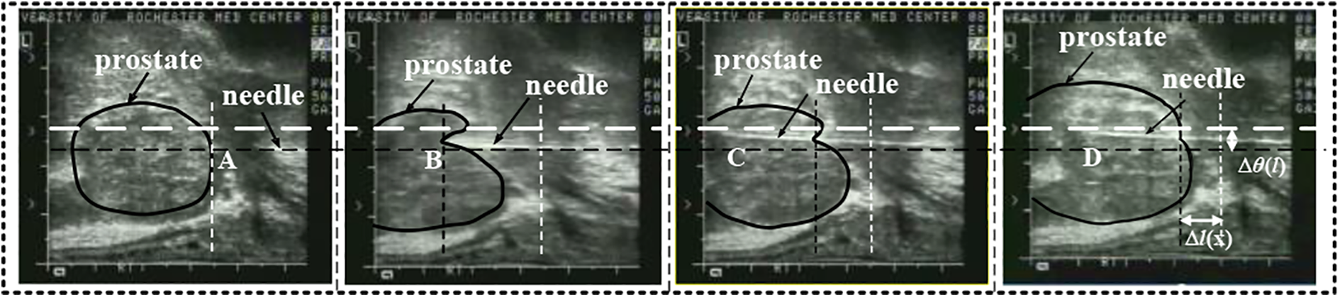
Single-needle insertion prostate process with TRUS. (a) Begin phase, (b) deformation phase, (c) full insertion phase, and (d) extraction phase. TRUS: transrectal ultrasound.
In LDR-BT, precise placement of needle and accurate delivery of radioactive seeds are very important and challenging. Some groups have adopted robot-assisted single-needle manipulation technology to improve the needle-targeted position. Majewicz et al. 6 presented a method for steering needle into soft tissue via bidirectional duty-cycled spinning and duty-cycled bevel flipping, through control of duty cycle time and direction to improve needle positioning accuracy. Tsumura et al. 7 studied the fast needle insertion method to minimize tissue deformation and damage. Khalaji et al. 8 proposed a vibration-assisted needle insertion technique to reduce needle–tissue friction. Our group 9 developed a piezoelectric vibration and rotation needle insertion device to improve positioning accuarcy to the template configuration restrictions. Above these approaches cannot use rigid needle body rotation drive to achieve the desired needle trajectory, that is, it is difficult to control rigid needle to compensate for target movements.
Due to the limitations of single-needle manipulation technology, some groups studied other assisted procedures (or soft tissue stabilization devices) combined with a separate needle drive mechanism to improve needle positioning accuracy in BT procedure. Podder et al. 10 proposed a method for prostate stabilization during transperineal LDR-BT, to effectively stabilize the prostate, one should either use needles possessing a retractable hook inserted in parallel or find the optimal angle for practical stabilization using regular BT needles. Because the needle insertion and seed delivery are performed manually, this group also developed multichannel robotic system that is capable of inserting a large number of needles concurrently and depositing seeds automatically, it is capable of inserting multiple needles and has the potential of reducing tissue deformation, edema, and maybe faster for seed implant. 11 The multi-channel system can overcome some of the drawbacks that may be encountered by the single-channel robotic systems; it is worth noting that the designed system can also be optimized to improve the ease of use by surgeons. Iranpanah et al. 12 designed a novel tissue stabilization device for magnetic resonance imaging (MRI)-guided breast biopsy; when combined with a separate needle drive mechanism, this stabilization device would enable in-bore MRI-guided breast biopsy. Pai et al. 13 proposed a simpler technique to improve prostatic BT seed placement, the first two needles are implanted simultaneously; through a prostatic BT grid, this reduces subsequent deflection of the prostate when using a seed implanter. In addition, there are some other studies showing that stiffer tungsten carbide needles, 14 modification of the transperineal grid reduce prostatic deflection, 15 the use of needles with incorporated electromagnetic fusion sensors, 16 mosquito proboscis-inspired needle, 17 a specially designed domed-cones template for needles fixation, and incline insertion in prostate implant BT, 18 this new technique can be further used on the soft tissue stabilization device.
Based on the investigation of the above literature, we adopt the scheme of robot control needle combined with tissue stabilization mechanism to improve the design of an articulated seed implantation robot. Aiming at the limitation of human body structure space and robotic kinematics dexterity requirements, our group developed a renal replacement therapy (RRT)-type cantilever articulated seed implantation robot for prostate cancer BT. 9 In the already designed RRT cantilever joint, we adopt high-power motors and speed reducers to improve the weight-to-payload ratio of robot end-effector. Surgical robots share the workspace with surgeons, and the use of such high-power motors may lead to a serious injury when a collision between surgeons and robots occurs due to surgeon misoperation or surgical robot malfunctions. 19 In this system, it is hard to achieve both low-power consumption, compact robot size, and safety using robotic cantilever at the same time. 20 We can address this issue by applying a gravity compensation mechanism to achieve the static equilibrium state passively in the entire workspace and improve the motion performance of cantilever joint drive. There have been several studies on the gravity compensation mechanism using springs. A mechanism based on springs and wires arrangement was suggested in Chung et al., 21 and a parallel four-bar linkage based on a pulleys and springs arrangement was suggested in Hull et al. 22 These studies show that springs can be used to provide a counterbalancing torque instead of a heavy external mass. One idea to reduce moving inertia is to use a novel springs mechanism, which is a feasible method for surgical robots. 23 By reviewing the topic of soft tissue stabilization mechanism and analyzing the shortcomings of previous design schemes of the robot, this study discusses the new static torque balancing method and multi-needle insertion soft tissue stabilization mechanisms that may be used in previously articulated seed implantation robots.
Counterbalance and multi-needles insertion soft tissue stabilization mechanism
In view of the above robot structural design problems, this article improves the RRT-type cantilever articulated seed implantation robot structure, mainly to complete the research work of robot arm with gravity torque counterbalance mechanism and multi-needles insertion soft tissue stabilization mechanism.
Counterbalance mechanism
The goal of the research is to design a balancing system that can produce appropriate torque and counteract the gravity torque of the robot arm. The flowchart shown in Figure 2(a) summarizes the procedure of solution of the balancing problem. The dynamic equations for robots with the balanced system are described as follows 19

where

Balancing system: (a) flowchart of the proposed procedure, (b) energy transfer, (c) gravity torque changes nonlinearly with θ, and (d) two types of springs with a 90° phase difference.
To simplify the analysis, we describe the design principle of the robot arm l 1 balancing system, while robot arm l 2 is similar. The robot arm l 1 rotates around the hinge pivot point O 0, θ 1 is rotation angle with the vertical line, m 1 the mass of the robot arm l 1, and the potential energy generated at the equivalent center of mass O 2 can be expressed as follows

Torque produced by gravitational potential energy

To fully compensate torque produced by the robot arm l 1 gravitational potential energy, we design the spring balance system at the hinge point O 2, two types of compression springs with a 90° phase difference, see as Figure 2(c). When the robot arm l 1 turn from the original position to the target position, spring displacement generated by a horizontal spring kv and a vertical spring kh can be expressed by the following equation

where lk is the straight-line distance from hinge point O 0 to hinge point O 1.
Then the elastic energy released by the horizontal spring and vertical spring is given by

Further solution, passive torque generated by the spring balancing system can be written as follows

Therefore, to realize the complete conversion of the elastic potential energy to the gravitational potential energy of the robot arm, equation (1) needs to be satisfied

Based on (3), (6), and (7), we can reach the following equation

Equation (8) is the static balancing equation of the robot arm’s gravitational potential energy and the balance system’s elastic energy, assuming Equation (8) conditions are met kv = kh = k,
Then

We finally reach the constraints of static balancing are as follows

If we want to achieve the gravity torque balance of robot arm l 1, we only need to meet equation (9), namely only to select spring with suitable stiffness coefficient and two types of springs are arranged on a 90° phase by using a cross-shaped slider and two restraint guidebars. This system can be extended for the robot arm l i case in the same way.
To adaptively balance the gravity torque of different robot arms, we improved the balance system. In the initial position of the robot arm, a preloaded displacement parameter α of the spring is introduced.
24
To add initial preload to vertical spring force at point O
2 and initial preload displacement is

According to equations (6), (9), and (10), the total torque generated by the spring balance system is as follows

where
Multi-needles insertion soft tissue stabilization mechanism
Without changing the existing clinical surgical equipment setting conditions, combined with the advantages of the above technology, this article studies the multi-needle insertion soft tissue stabilization technology and designs a simultaneous insertion of multi-needles fixation device.
The soft tissue is boiled down to viscoelastic materials, and the force is regarded as a combination of classical springs and dampers representing the elasticity and viscosity, respectively. 25
Thus, we used a nonlinear spring–damper model to establish multi-needles insertion soft tissue force model as shown in Figure 3.

Multi-needles insertion soft tissue force model: (a) nonlinear spring–damper system, (b) view of needle insertion in xy plane, (c) view of needle insertion in xz plane, and (d) force distribution and soft tissue displacement.
Multi-needles axial insertion force balance equation in the x-direction (Figure 3(d)) can be expressed as follows

where f insertion is the total axial insertion force in the x-direction, ffi is the friction force on each of the needle, i is the serial number of multi-needles, fni is the normal compressive force on each of the needle shaft, θ is the angle between bilateral needles, when θ=0°, four needles are inserted in a parallel configuration, and 0°<θ<90°, four needles are inserted into an angulated configuration, and fr is the resultant resistive force.
Because soft tissue follows nonlinear spring–damper behaviors, the resultant resistive force can be expressed as follows

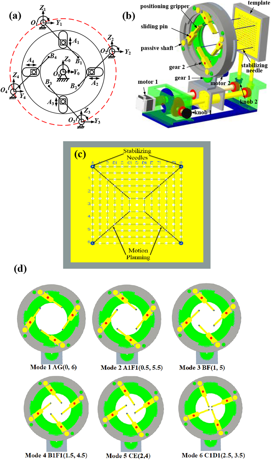
where m is the mass of prostate tissue, ci
is the equivalent nonlinear damping factor, ki
is the equivalent nonlinear spring factor, and
where k is the spring constant and c is the damping constant, x 0 is the initial displacement of prostate tissue, and p and m are negative real numbers.
It is assumed in equation (13) that the needle has sufficiently large values of v 0, the steady-state friction force can be obtained as follows

where μ c is coulomb friction coefficients, σ 2 viscous damping, and v 0 is needle insertion velocity. And fni is the normal compressive force on the needle which is a function of the needle diameter d, the length of the needle in the soft tissue l, and tissue property ξ.
Design of seed implantation robot with counterbalance and soft tissue stabilization mechanism
Our group has developed an RRT-type cantilever articulated seed implantation robot for prostate cancer BT in previous work. 26 For robot structural design problems, in this study, we improved the previous seed implantation robots, which are equipped with counterbalance and soft tissue stabilization explained in the second section as shown in Figure 4. We design a variable static torque spring balancing device under some conditions as shown in Figure 5. The mass of robot big arm m = 7.5–10 kg and link length l 1 = 0.166 m, r 1 = 0.04 m, and spring stiffness meeting conditions in equation (10) are calculated as follows


Improved design of a seed implantation robot.

The spring balancing system: (a) design of the robot big arm’s balancing device and (b) design of the robot small arm’s balancing device.
Then, at 0< θ <π/6, maximum spring displacement becomes

Similarly, the configuration parameters of the vertical spring and the horizontal spring of the small arm gravity torque balancing devices are calculated according to equations (17) and (18) as presented in Table 1.
Spring configuration.

1: robot arm l 1; 2: robot arm l 2..
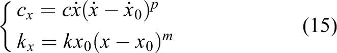
Figure 6 is designed as a variable multi-needle soft tissue stabilization insertion device with six working modes. It consists of a rotary table (gear 2), four chutes with uniform circumference distribution, four positioning gripper, four stabilizing needles, a pair of spur gear (gear 1 and gear 2), two drive motors, a template, and so on. The rotary table (gear 2) is connected with the positioning gripper through four sliding pins shaft and four chutes. Figure 6(a) shows its kinematic drawing using slider–rocker mechanism. Rotary table rotates around the X 0 axis. There are four equal circumferential distribution chutes on the rotary table. Positioning gripper is installed on the fixed table through the passive joint axis (X 1∼X 4). Positioning gripper (Oi−Bi, i = 1∼4) is connected with the chute through sliding pins shaft (Ai , i = 1∼4), and sliding pins shaft can slide and rotate in chute. A puncture needle is fixed at the end of positioning gripper (Bi , i = 1∼4). Four stabilizing needles in the YZ plane positioning by four groups of the slider–rocker mechanism. Figure 6(b) shows a more detailed design of the above scheme. Meanwhile, we provide clinicians with manual (two knob drive) and electric (two motor drive) two driving methods for the multi-needle insertion (back and forth X-motion). Furthermore, a guide template can be adjusted the Z-motion by manual knob drive 2.
Multi-needle insertion soft tissue stabilization device with six working modes: (a) four stabilizing needles kinematic drawing using slider–rocker mechanism, (b) design of the multi-needles insertion device, (c) different position coordinates of the four stabilizing needles in the YZ plane of prostate template, and (d) position coordinates of multi-needles tip in the template.
Figure 6(c) and (d) shows the design principle of the variable multi-needle soft tissue stabilization insertion device with six working modes. The six-working mode is determined based on six different position coordinates of the four stabilizing needles in the YZ plane of prostate template. The designed six different position coordinates basically cover the overall size of the prostate template, which is easy to adapt to insert the different sizes of prostate tumor volume. The corresponding relationship between specific position coordinates of multi-needle tip in the template and working mode are defined as follows
Mode 1: AG (0, 6)—y and z coordinates of the four stabilizing needles in the template;
Mode 2: A
1
F
1 (0.5, 5.5) —y and z coordinates of the four stabilizing needles in the template;
Mode 3: BF (1, 5); Mode 4: B
1
F
1 (1.5, 4.5);
Mode 5: CE (2, 4); Mode 6: C
1
D
1 (2.5, 3.5).
The switch of position coordinates in each working mode is realized by DC motor drive control. A pair of spur gear (gear 1 and gear 2) are driven by the DC motor. When gear 1 inputs different angular displacements, gear 2 rotates to the corresponding working mode. When precisely controlling the input angular displacement, each mode can be accurately positioned and adapted to stabilize the different sizes of prostate tumor volume. Once it is determined which work mode needs to be executed, the first four needles are introduced simultaneously on either side of the midline. By this method, the prostate is fixed, thus reducing rotation of the prostate and enabling subsequent needles to be inserted accurately.
Simulations and experiment
Simulations I—Torque and equivalent gravity balancing distribution with the spring balance system
Substitute the spring design parameters in Table 1 into equations (3) and (6) to obtain the relationship between τA and τB generated by the vertical spring and horizontal spring, respectively, in Figure 7 describes the relationship between τA , τB , and the robot arm gravity moment τg . Because the spring torque is converted to vertical force at the robot arm end, therefore the equivalent gravity to be balanced for is expressed as follows

where γ is the balancing coefficient (
Force wA borne by the vertical spring and force wB borne by horizontal spring are expressed as follows


Torque balancing distribution: (a) the robot big arm with the spring balance system and (b) the robot small arm with the spring balance system.
The numerical simulation results of torque and equivalent gravity balancing distribution are shown in Figures 7 and 8. When α = 1.25 or α = 2, when the weight of the robot arm becomes 1.25 mg or 2 mg, by adjusting the initial preload of the vertical spring kv
,

Equivalent gravity balancing distribution: (a) the robot big arm with the spring balance system and (b) the robot small arm with the spring balance system. 1—wG = 1 mg, 2—wG = 1.25 mg, 3—wA ′−κ = 1.25, 4—wA −κ = 1, 5—wB . 1—wG = 1 mg, 2—wG = 2 mg, 3—w A′−κ = 2, 4—w A−κ = 1, 5—w B.
Experiment II—Quantitative experiment of the spring balance system
To verify the effect of the designed robot arm’s balancing system, we adopt data acquisition window, angle sensor (TMCW8 TRIONS, Qingdao, China), digital dynamometer (CFG + 200, Mecmesin Inc., UK), electronic handwheel (MS106 -1 c—BCD, SECONA, Suzhou, China), robot prototype system, and spring torque compensation device completed the comparison experiment under two loads. The measurement results are shown in Figure 9. During the experiment, the robot big arm is controlled by the electronic handwheel within the range of θ∈[45°, 95°], hovering every 5°. With or without the spring balance system, the rotation angle displacement of the robot arm θi and the applied torque τi are collected at the same time. After the AD sensor conversion data and the RS232 serial port transmission, the original sensor simulation data are displayed and recorded under the developed data acquisition window. Each group repeats the measurement five times and takes the average value.
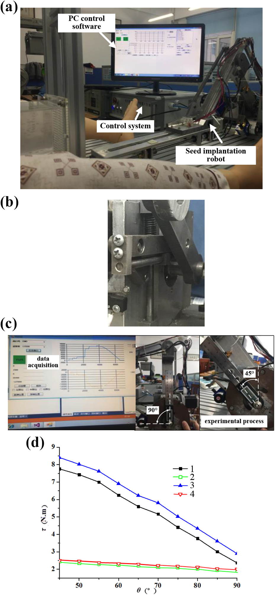
Quantitative experiment: (a) Robot prototype system, (b) prototype of spring torque compensation device, (c) experiment procedure, and (d) experimental measurement results. 1—under vertical load 1 kg, without the spring balance system, 2—under vertical load 1 kg, with the spring balance system, 3—under vertical load 2 kg, without the spring balance system, and 4—under vertical load 2 kg, with the spring balance system.
Figure 9 is a comparison of the performance of the spring balance system under two loads. τ is the rotation torque value. After installing the balancing device, during the process of increasing θ from 45° to 90°, the unbalanced gravity torque is about 2.2 N.m, which is mainly caused by the inaccurate friction and spring parameters. Under the vertical 1 kg load, the average load torque is reduced by 3.096 Nm and the torque fluctuation is reduced by 1.694 Nm; under the vertical 2 kg load, the average load torque is reduced by 3.638 Nm and the torque fluctuation is reduced by 1.406 Nm. Compared with other typical schemes of spring gravity torque compensation devices used in the robot arm, the results’ comparison is presented in Table 2. Since the year 2014 up until 2020, the experimental results in the literature showed that researchers were gradually trying to improve the structural arrangement of the spring compensation system for the robot. According to maximum torque percentage reduction, various spring gravity torque compensation systems have relatively good effects on industrial robots and service robots. It also shows good application prospects in medical robots. But the spring gravity compensation in our system is not able to compensate the friction torque of the robot’s motor and rotating joint during or prevent all the effects of external disturbances. An integrated active and passive gravity compensation method for our robot needs further research and evaluation. In general, the spring gravity compensation system can also reduce the fluctuation of joint drive torque, and combining this topic with the control system design to improve the stability of joint drive is also being studied. 27
Comparison of existing spring gravity torque compensation device for the robot.

Simulation III—Displacement of multi-needles insertion into soft tissue
In the displacement simulation process of multi-needle insertion prostate tissue, applied insertion force approximates a step function, that is,
Simulation parameters.

From the plots in Figure 10, the red line is a single-needle insertion displacement simulation, the blue line is multi-needle insertion displacement simulation, and it is observed that multi-needles insertion strategies have better effect on displacement in the y-direction or z-direction. In the x-direction, the maximal displacement is 15.84 mm, but in the z-direction, it is approximately 0.22 mm.

Displacement simulation of different numbers of needle insertion prostate tissue.
Compared with typical single-needle insertion prostate tissue, the results’ comparison is presented in Table 4.
Maximum displacement comparison of needle insertion prostate tissue.
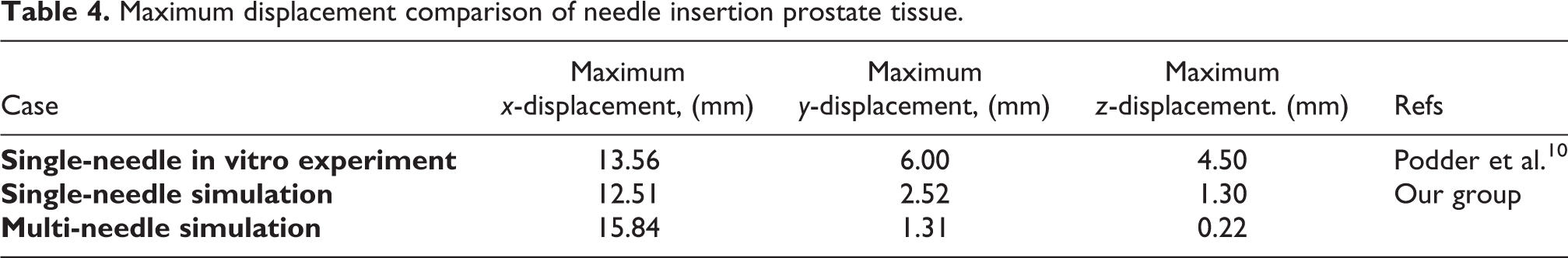
According to the maximum displacement of needle insertion prostate tissue as presented in Table 3, multi-needle insertion soft tissue stabilization shows good application prospects in BT procedure. Combined with a separate needle drive mechanism, it can limit its lateral deformation and displacement, and this mechanism maybe reduces rotation of the prostate and enabling subsequent needles to be inserted accurately. However, multi-needle insertion is relatively increased the resultant resistive force fr and dynamics friction force ff , specific reference equation (16). In the X-direction, the displacement is increased, and in the Y- and Z-directions, the displacement is reduced, and the displacement changes more smoothly. While the simulation is in the ideal case, the multi-needle puncture mechanism could reduce prostate displacement in the y- or z-direction. If we using the first four needles that are introduced simultaneously on either side of the midline, by this method, the prostate may be fixed in BT procedure.
Conclusion
This article improves the RRT-type cantilever articulated seed implantation robot structure. Compared with the existing balancing system schemes, this article adopts the idea of mutual conversion of gravitational potential energy and elastic potential energy and establishes a static balancing model. With preloaded displacement parameter of the spring α, the variable gravity torque balance of robot arm can be achieved. Torque and equivalent gravity balancing distribution with the spring balance system and the quantitative evaluation experiment were performed, and experiment results provide evidence that the spring balance device can basically compensate the gravity torque of the robot arm. At the same time, the reduction of torque fluctuations can also improve the driving stability of the seed implantation robot.
A variable multi-needle soft tissue stabilization insertion device with six working modes is designed with six working modes. The six-working mode is determined based on six different position coordinates of the four stabilizing needles in the YZ plane of prostate template. The designed six different position coordinates basically cover the overall size of the prostate template, which is easy to adapt to insert the different sizes of prostate tumor volume. The switch of position coordinates in each working mode is realized by DC motor drive control. A pair of spur gear are driven by the DC motor. When gear 1 inputs different angular displacements, gear 2 rotates to the corresponding working mode. When precisely controlling the input angular displacement, each mode can be accurately positioned and adapted to stabilize the different sizes of prostate tumor volume. Once it is determined which work mode needs to be executed, the first four needles are introduced simultaneously on either side of the midline. By this method, the prostate is fixed, thus reducing rotation of the prostate and enabling subsequent needles to be inserted accurately. Initially completed displacement simulation of different numbers of needle insertion prostate tissue, experiment results indicate that multi-needle puncture mechanism could reduce prostate displacement in the y- or z-direction. By this method, the prostate may be fixed, thus this mechanism can reduce rotation of the prostate and enabling subsequent needles to be inserted accurately. We hope that our study may be used for other similar surgical procedures that are under development. Future work includes a quantitative investigation of the multi-needles insertion tissue damage, the needle slenderness ratio, and the viscoelastic tissue response for improved design.
Footnotes
Declaration of conflicting interests
The author(s) declared no potential conflicts of interest with respect to the research, authorship, and/or publication of this article.
Funding
The author(s) disclosed receipt of the following financial support for the research, authorship, and/or publication of this article: This work was supported by the National Natural Science Foundation of China (Grant No. 61741101), the Youth Top-notch Talent of Anhui Polytechnic University; the National Natural Science Foundation PreResearch Project of Anhui Polytechnic University (Grant No. 2019yyzr11), the Key Technologies R & D Program of Anhui Province of China (Grant No. 202004a05020013), and the Innovation Team of Anhui Polytechnic University, Natural Science Research of Major Program; Universities in Anhui Province, China (Grant Nos. KJ2019A0155, KJ2019A0147, and KJ2020AO18).