
Abstract
This article focuses on the structural design of a surgical robot for radioactive prostate seed implantation and the position detection algorithm for the puncture needle. A seed implantation robot with the ability to pierce with force and receive image feedback is created to increase the positioning precision and puncture stability of the robot as well as to determine the real-time position of the puncture needle. Compared with existing puncture schemes, we use a statistical model approach for classification and a deep learning-based target detection algorithm. Since different human tissues have different structural properties, we conducted quantitative puncture experiments, and the experimental results demonstrated that this puncture scheme can effectively discriminate the punctured tissue and position the puncture needle tip, significantly improving the success rate of surgical radioactive seed implantation procedures.
Introduction
Currently, prostate cancer is a common malignant tumor in men, for which radioactive seed implantation is an effective treatment. 1 Prostate brachytherapy is highly effective, has fewer side effects, and results in a smaller wound and quicker recovery. 2 Conventional prostate tumor treatment surgery is generally performed with a puncture needle-guided template to determine the puncture location. Physicians manually implant seeds into the target location under the guidance of transrectal ultrasonography (TRUS), magnetic resonance imaging (MRI), or computed tomography (CT). 3 In clinical surgery, commonly 15 to 20 needles are implanted, and 80 to 120 seeds are placed in the target location. Due to human factors (surgical fatigue of surgeons, error in judgement and inaccurate control of the puncture force), the seed displacement or the tissue location may be incorrectly determined, which may adversely affect the clinical outcomes.
In the actual surgical procedure, the surgeon determines the tissue location through the feedback force of the scalpel based on their experience. After tissue bleeding, which can directly affect visual information acquisition, tactile information becomes essential. 4 Over the past decade, significant developments have been made in integrating robotic brachytherapy for radioactive seed implantation. 5 These systems are designed to reduce the limitations of robotics and improve the precision and surgical efficiency of seed implantation.6–11 In 2006, Podder et al. at the University of Rochester performed brachytherapy needle insertion experiments on the prostate patients by placing a six-dimensional force sensor mounted on the tail of the puncture needle to capture the change in puncture force during the puncture. The force transducer measured a puncture value of approximately 7 N for the prostate and an average puncture force of approximately 15 N. 12
Accurately modeling the tissue−needle interaction force has been difficult in robotic surgery. To enhance the force feedback signal and reduce the interference component in the tissue interaction force during puncture, Ferro et al. proposed a method to identify and remove the friction component, thereby enhancing the force signal and predicting the interaction force between the puncture needle and the tissue. The accuracy of the puncture force was improved by increasing the ratio of useful information to total force by subtracting the frictional component of the previous layer as the puncture needle passed through different tissue layers. 13 Shah et al. designed an adaptive finite element model that accurately predicted the stress distribution of the needle in contact with the tissue, which stimulated the field of needle–tissue interaction. 14 However, seed implantation and biopsy needles are mainly single-bevel needles, which tend to tilt to varying degrees as the depth of penetration increases due to the inability to counterbalance the bending moments generated during the penetration process, leading to failure of the procedure. Li et al. designed a multi biopsy needle by developing a new model of needle deflection and tissue deformation, which can reduce the needle deflection by 87% compared to a single bevel needle. 15
During surgery, it is difficult to ensure the stability of the puncture due to soft tissue deformation, respiratory movements of the body, and so on. Therefore, real-time control of the puncture needle is needed. Hans used a robust control algorithm, that is integral sliding membrane control (ISMC), for needle steering control while replacing the discontinuous components of the puncture process by super torsion control (STC), which eliminates the jerky motion of the needle. 16 Hans et al. also proposed continuous higher-order sliding membrane control, which was realized by a robust second-order sliding membrane controller, which achieves needle convergence in a two-dimensional plane. 17 Through constant research on control algorithms, some teams have accurately controlled the puncture needle by adaptive slip film control, which reduces external interference and improves the intelligence and intervisibility of percutaneous puncture.18,19 However, most of the current needle control algorithms are more complex; Kaushik Halder's team simplified the existing controllers and proposed a fuzzy-based controller based on kinematics inside the tissue domain and a Lyapunov analysis-based fuzzy rule base for a fuzzy inference system, which experimentally showed an average error of 0.0172 mm in the Y–Z plane. 20 In the same year, based on the above, the team proposed an adaptive neuro-fuzzy inference system (ANFIS) based on the intervention of neural networks to improve accuracy further. 21 Behera et al. proposed a multilayer perceptron technique based on an adaptive learning rate to predict Young's modulus for tissue puncture by artificial neural network, which employs an adaptive learning rate to improve data processing and learning efficiency. The predicted Young's modulus has high accuracy, which helps to determine the deflection size of the puncture needle and improve the puncture accuracy. 22
Ultrasound (US)-guided percutaneous puncture technology can realize real-time, minimally invasive interventional therapy without radiation. By planning the puncture path on the US image obtained from the scan of the lesion site, calibration between the US image and the robot end-effector was performed, reducing the robot's puncture localization error. The average puncture localization and orientation accuracies were 1.16 ± 0.45 mm and 1.25 ± 0.56°, respectively. 23 An automated needle tracking method for 3D US imaging improves the puncture needle visualization problem during the puncture process. A CNN (convolutional neural network) model was used to detect the needle position and needle orientation angle at a frame rate of 3 Hz. The experiments yielded average errors of 1 mm and 2°. 24
As mentioned above, this article selects the puncture force feedback and image feedback of a prostate radioactive seed implantation robot as the research object, addresses the problem of the interdimensional coupling of multi-dimensional force sensors, and directly reads the voltage signal output from each dimensional amplifier circuit based on the assumption of a linear relationship between the output signal and the acting force. The needle tip position is detected by a binocular camera and an object detection algorithm. 25 This article reviews the subject of radioactive seed implantation robots, analyzes the shortcomings of previous robot design solutions, and discusses new robot design methods and image processing solutions.
Feedback mechanism of the puncture process
At different stages of the puncture process, the punctured tissue and the puncture needle undergo corresponding deformation. The puncture needle is subjected to different puncture forces, which can generally be divided into four typical force stages: before puncture, at the critical point of tissue deformation, after the tissue is punctured, and after withdrawal of the puncture needle. 26 Experiments have shown that the stiffness force steadily increases before puncture, that there is an extreme point of stiffness force before puncturing the tissue, and that the force acting on the puncture needle after a puncture is the combination of the frictional force and cutting force at the needle tip position.
Puncture force feedback mechanism
Different human tissues present complex tissue structures. During prostate puncture surgery, the needle must constantly puncture different human tissues, and the force continuously changes. During prostate treatment, the needle must puncture the human epidermis, perineum, and prostate tissues. To improve the success rate of the procedure, we provide the seed implantation robot with an intraoperative control function with puncture force sensing. If the seed implantation robot is equipped with a puncture force sensing system, then it will know whether the puncture needle pierces the prostate. 27
In the example shown in Figure 1, if the puncture needle reaches the target point (the dot in the figure), then the puncture needle must have passed through the perineum and punctured the prostate surface before reaching the target. On the other hand, if no prostate puncture is detected, then the puncture needle must not have reached the location set preoperatively (the dot in the figure).

Principle diagram of the prostate puncture procedure.
Due to the interaction between the needle and the tissue, when the needle is inserted into different tissues, the mean puncture force and the puncture force curve characteristics are different, as shown in Figure 2. Through a large amount of deep learning training, when the characteristics of two tissues differ greatly, the puncture force can be classified.

Puncture force curve: (a) liver tissue puncture curve and (b) lesion tissue puncture curve.
We refer to events as specific types of tissue punctures so that event classification can be considered a tissue classification problem. We chose porcine liver for the puncture experiments due to its relative proximity to human liver in terms of anatomical structure and physiological function, as well as its better availability, cost-effectiveness, and less ethical controversy. There are two different kinds of events for liver puncture experiments: liver tissue excision and lesion tissue puncture. In this article, a dichotomous Bayesian classifier is used for classification. The Bayesian classifier calculates the probability of giving a random variable x using the Bayesian formula.

When a puncturing process is detected, the probability that the puncture force belongs to each category is calculated. The event is classified as the category with the highest probability. The selected category is represented by the highest posterior probability, which is usually expressed as:

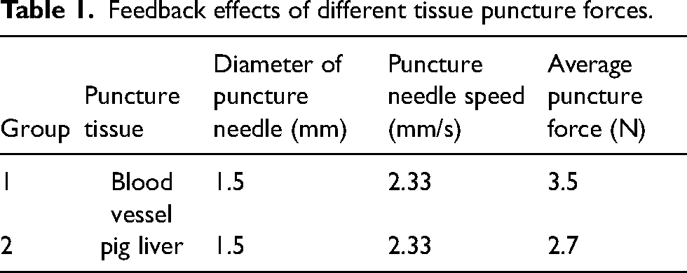
To control the performance and obtain the training model, the following tissues were punctured for experiments in this article. The table shows the average puncture force and puncture amplitude effects for different tissues, puncture forces, and puncture needle diameters. The differences between the different tissues are shown in Table 1.
Feedback effects of different tissue puncture forces.
Puncture image feedback mechanism
The human−machine interface of the radioactive seed implantation robot includes the display of the puncture needle tip position, real-time display and control of the puncture needle speed, and an online display of the puncture force. This article uses Qtcreator software for development, the Qt GUI library and vision processing library are selected for image processing, and the programming language is C++, as shown in Figure 3.
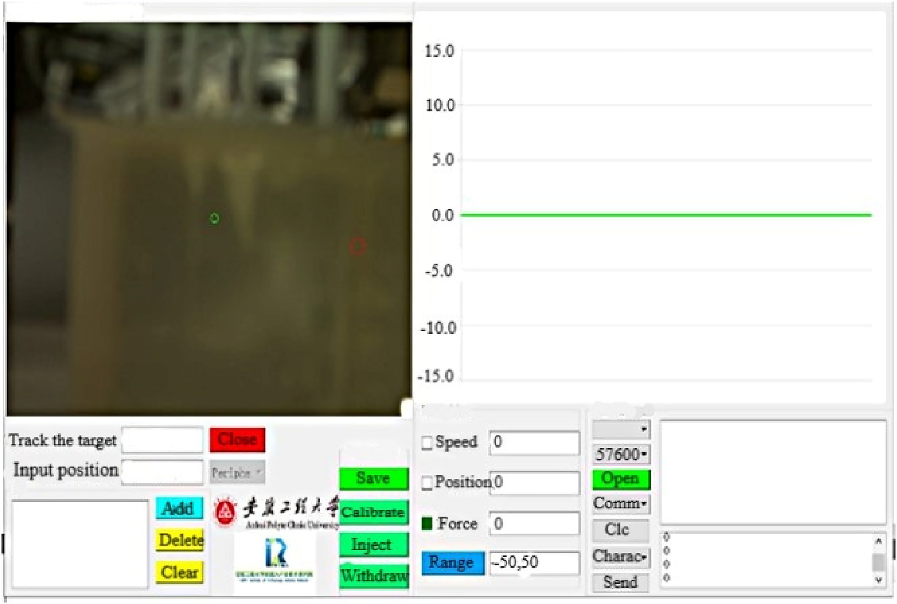
Human−computer interaction system interface.
The human–computer interaction system mainly consists of image processing, data display, and communication parts.
Image processing. The images from the two cameras were read, and the images captured in real time were simultaneously processed. Silicone was detected with an edge using a Hough straight line, and the equation of the straight line where the needle was located was filtered. Data display section. Using the QtChart module, the data waveforms, such as the puncture force and external needle feed speed collected online, are displayed. Communication. The UART communication interface and communication checksum method were used for the CRC16 redundancy checksum.
The aluminum alloy bracket is chosen to build the visual tracking camera fixed platform, and the camera is adjusted on the side to level with the ground. Then, the vertical downward camera is adjusted to the ground vertical using the plumb line to complete the camera installation and adjustment, as shown in Figure 4.
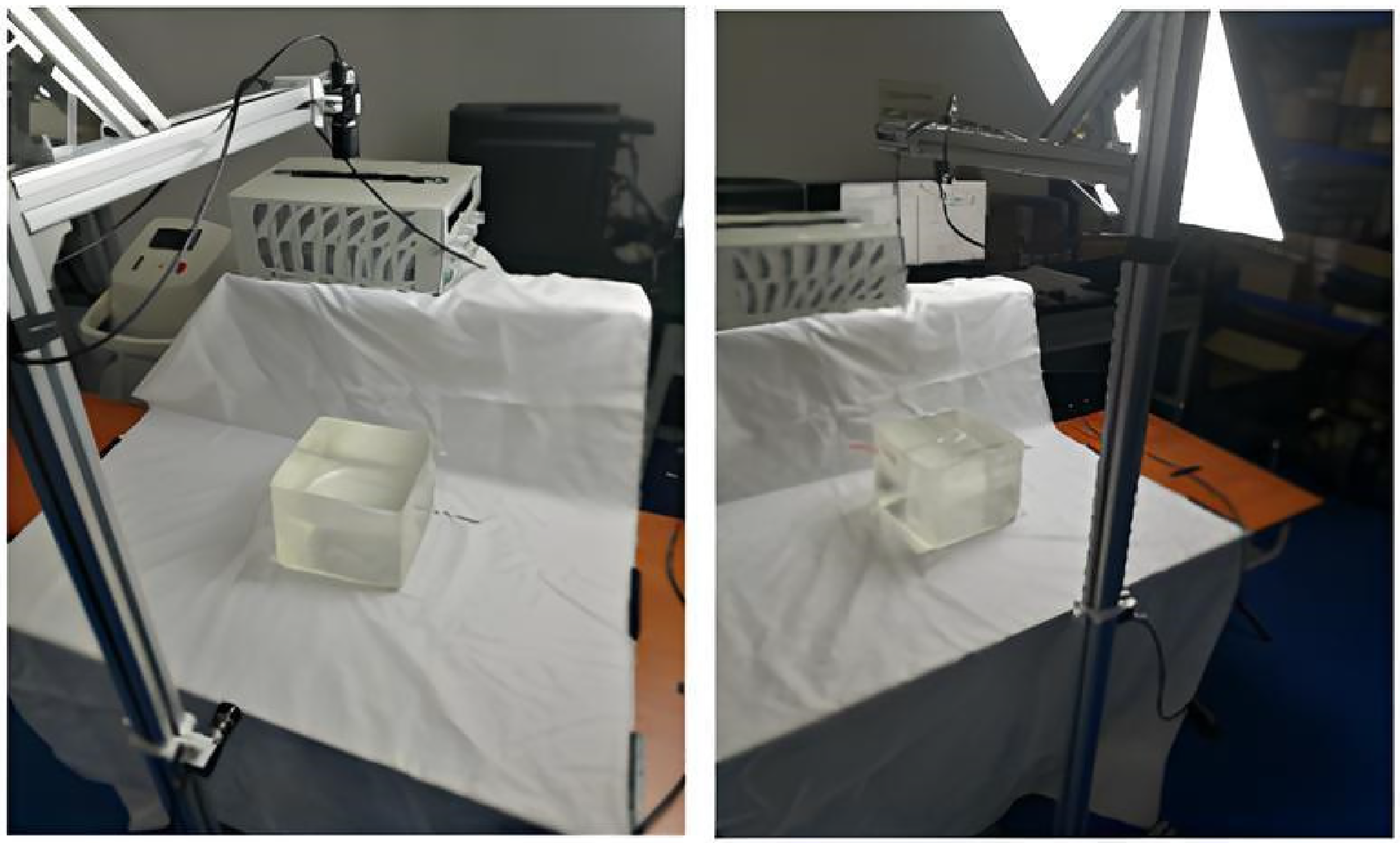
Binocular vision tracking camera unit.
Two subthreads are set up to read the images acquired by the two cameras for synchronous processing, and the processed images are shown in Figure 5. The code is shown below: if(cap.isOpened()) { Mat des; cap.read(des); if(des.empty()){ qDebug() << “ Image 0 is empty! “; continue; } flip(des, des,1); resize(des, des,Size(my_video_width, my_video_height)); cvtColor(des, des,COLOR_RGB2BGR); image_analysis(des); mutex.lock(); des_over = des.clone(); mutex.unlock(); waitKey(40); emit update_paint_event(); }

Image preprocessing.

Faster-RCNN algorithm flow chart.
Faster R-CNN target detection algorithm
The feature images are processed using the region-based convolutional neural network (Faster-RCNN) target detection algorithm, which can greatly improve the processing speed and quality of the candidate regions. 28 The region proposal network (RPN) is used instead of the selective search (SS) algorithm to obtain candidate regions, as shown in Figure 6.
After the convolution layer processes the input image, the feature image is input to the RPN and processed with a 3 × 3 sliding window. The fully linked features obtained after processing are divided into a cls layer and a reg layer. To adaptively adjust the size of the candidate box, the anchor concept is introduced in this article, as shown in Figure 7.

Anchor structure diagram.
In this article, the Laplace sharpening method is used to determine the template coefficients using the differential coefficients, and then the convolution calculation is performed to achieve sharpening filtering. The Laplacian image operator is defined as: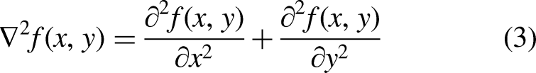


After filtering the extracted straight line, as shown in Figure 8, for the line needle trajectory detection, the grayscale image is traversed along the straight line. If the white line is interrupted by a long distance, the point is considered the location of the needle tip on the two-dimensional map.

Needle tip position: (a) needle track detection and (b) two-dimensional coordinate acquisition of the needle tip.
Design of a seed implantation robot with puncture force and an image feedback mechanism
The puncture force detection sensor and the radioactive seed implantation robot have an integrated design. The prostate radioactive seed implantation robot is shown in Figure 9, which includes a realman robot (RM), a seed implantation device, a six-dimensional force sensor, an STM32F4 microcontroller development board, a computer, and a 24-V power supply. The effective movement distance at the end of the robot is 140 mm, and the maximum movement speed is 140 mm/min.
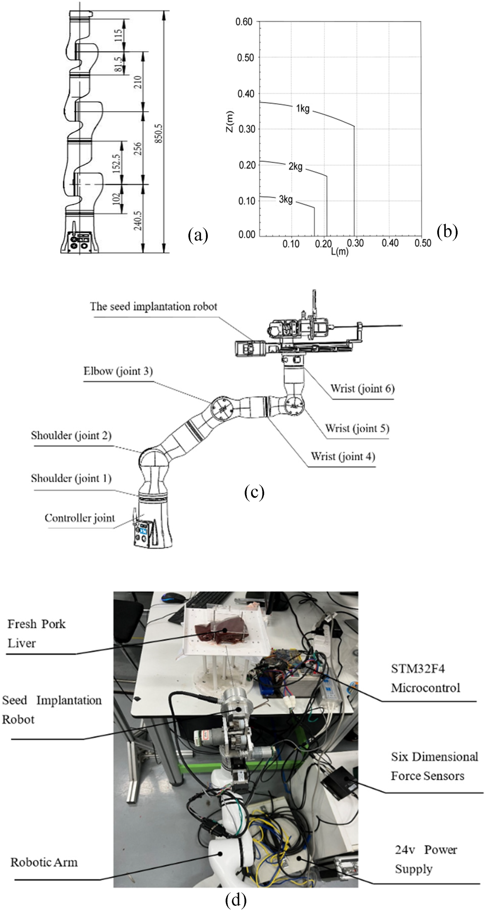
Experimental platform: (a) dimensional drawing of robot joints, (b) robot end load profile, (c) robot 3D model, and (d) physical picture.
The robot has a modular design with joints and an integrated controller at the bottom, eliminating the need for a control cabinet. It is possible to control the rotation of each joint of the robot to move the robot end tool to different positions. The specific parameters of the robot are shown in Table 2.
Robot specific parameters.

The motion of the radioactive seed implantation robot designed in this article completely simulates the surgical process. The robot mainly consists of an external needle driver and an implantation wire driver. The external needle driver drove the puncture needle to advance on the screw, and the implantation wire driver completed the seed implantation work, as shown in Figure 10.
1. Calculation of the load inertia ratio. The maximum load bearing of the screw W is 3 kg, the length of the outer pin-driven screw BL is 160 mm, the outer diameter of the screw BD is12 mm, the screw guide distance BP is 5 mm, the mechanical efficiency of the screw Be is 0.9, and the rotational inertia of the screw Jc is 10 × 10−6 kg m2. The mass of the screw is Bw.


Structure of the seed implantation robot.
The load inertia is: 2. Strain gauge bridge. Four resistance strain gauges form a full differential constant current bridge, as shown in Figure 11. When R1 = R2 = R3 = R4 = R, the resistance on both sides of the bridge is balanced. According to the principle of current balance, the following relationship is obtained: 3. Constant current source. A constant current source circuit was constructed using the LM317 voltage regulator chip, as shown in Figure 12. The current flowing across resistor R1 is:


Constant current drive bridge.

Constant current source circuit.
The adjustment current 

External needle device.
The radioactive seed implantation robot system component modules can be simplified as robot bodies, robot motion units, information sensing units, and human–computer interaction interfaces, and the principle of the radioactive seed implantation robot system is shown in Figure 14.
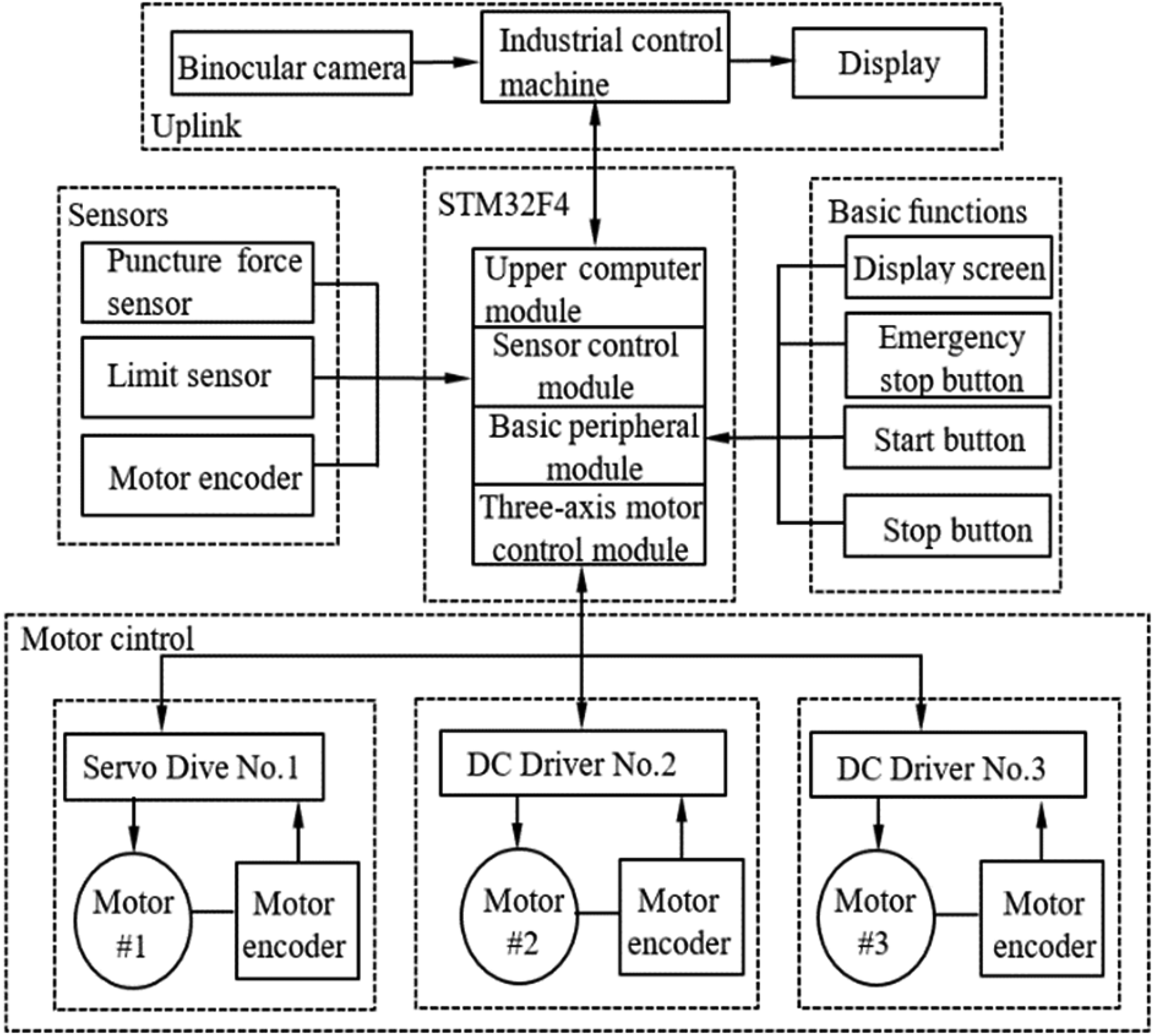
Principle of the radioactive seed implantation robot system.
Experiment
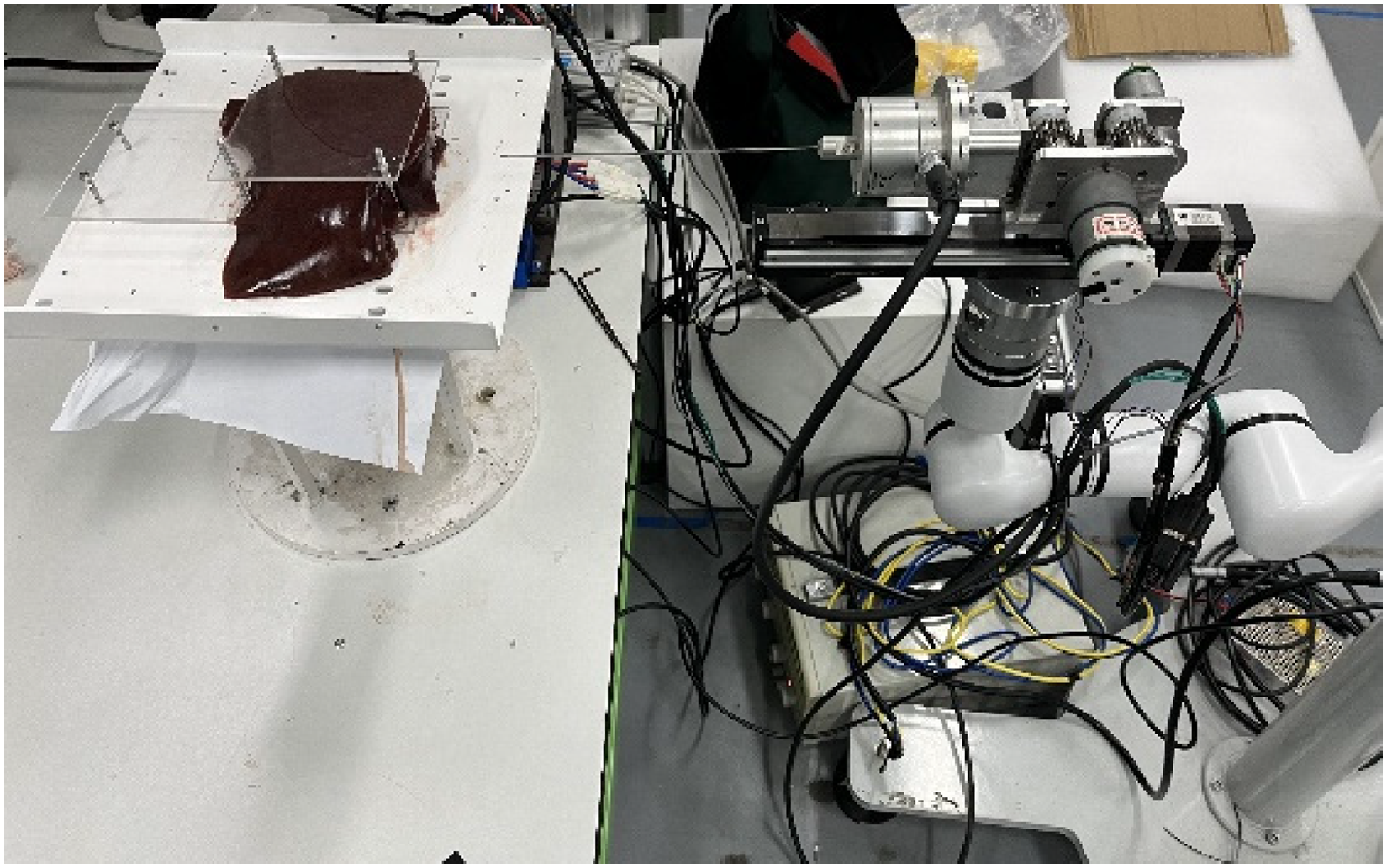
To verify the puncture effect of the designed radioactive seed implantation robot, the seed implantation robot is mounted on the end of the RM robotic arm to accomplish the puncture effect at different locations. The experimental equipment is shown in Table 3. Excluding the cylindrical space directly above and below the robot base, the working range of this robot is a sphere with a radius of 610 mm, as shown in Figure 15. The robot provided the experimental conditions for the puncture experiments in this article.

Schematic of the reachable space of the robot.
Experimental equipment.

Experimental I—puncture force testing effect of different models
To verify the puncture effect of the designed seed implantation robot, fresh pig liver was used to conduct simulation experiments, as shown in Figure 16.

Pig liver sample.
The experimental process can be divided into six stages: no-load, puncture, advance damping, stopping the needle, exit damping, and no-load. The pig liver puncture procedure as shown in Figure 17.
Pig liver puncture procedure.
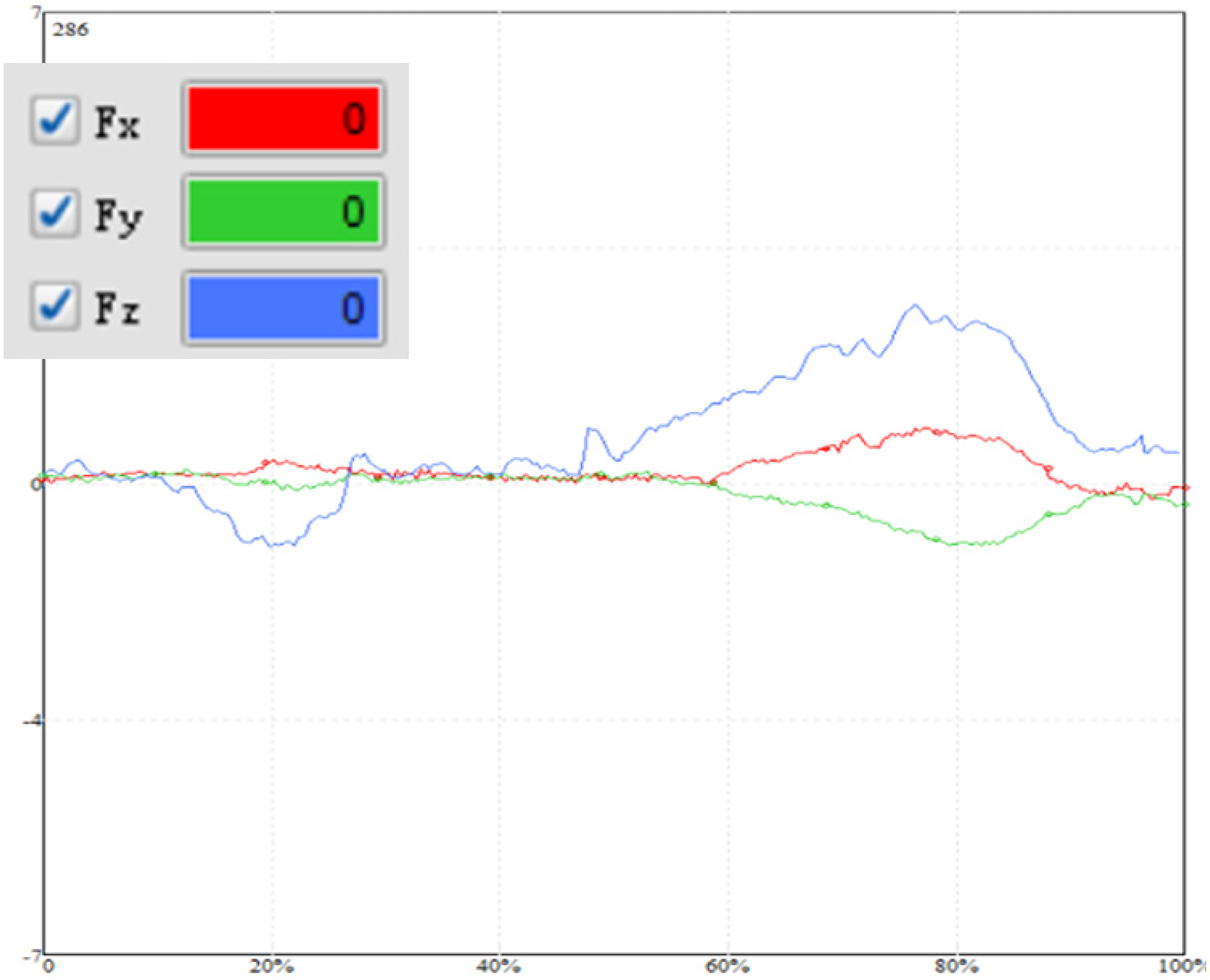
The force curve of the puncture needle measured by the six-dimensional force transducer is shown below, and the curve fluctuation is mainly attributed to tissue inhomogeneity.
As shown in Figure 18, the first wave was caused by the puncture needle piercing the outer skin of the pig liver; the second sudden drop in force was caused by piercing the tissue; afterward, the force remained the same, and the main force in this stage was friction; the last sudden drop in force was caused by the reverse motion of the needle, which led to a change in the deformation direction of the pig liver tissue. The data were processed, and the average puncture force was 2.7 N. By intercepting the force data and filtering the interference curve, the following data plots were obtained, as shown in Figure 19.

Needle feed force curve.
Force data analysis chart.
The filtering criterion was a mean of 3% of the total data volume + 3*standard deviation of 3% of the total data volume.
To verify the feasibility of the device, as shown in Figure 20, this experiment used sponge balls instead of diseased tissue and embedded them inside the pig liver to simulate human diseased tissue puncture experiments.

Simulation experiments: (a) sponge balls and (b) puncture experimental samples.
The puncture needle further contacts the sponge ball after puncturing the tissue, and the puncture force increases again due to the force of the sponge ball, as shown in Figure 21.

Needle feed force curve.
Since the sponge ball is inside the pig liver, it may move when performing puncture, as well as the uneven distribution of material inside the sponge ball, resulting in large fluctuations in the force curve. However, the sudden change in the curve is noticeable and does not affect the experimental results.
Experiment II—puncture needle position tracking experiment
When the force sensor data changes abruptly, the needle tip touches the silicone surface, and the encoder and image are positioned above zero. Simultaneously, the camera acquires images of the needle tip position, and the image processing module scans and determines the puncture needle tip position. The coordinate value calculated by the encoder and the coordinates positioned by the image are synchronously processed to complete the needle tip position tracking. The specific processing steps are shown in Figure 22.

Flow chart of the upper computer system.
The upper computer issues a puncture command, at which time the puncture needle is displaced forward and enters the binocular camera image field. The imaging system begins to identify the needle tip position and track the position of the needle tip. As shown in Figure 23, the green circle denotes the center of the silicone, and the red circle denotes the location of the needle tip.

Binocular camera image: (a) horizontal image and (b) vertical image.
To ensure the accuracy and credibility of the experiment, ten sets of controlled experiments are conducted in this article, as shown in Figure 24. The upper computer controls the robot arm movement and seed implantation and simultaneously records the position of the point under the relative coordinate system.

Control experiments: (a) reaching the first point and (b) reaching the tenth point.
Figure 25 shows the ten-time repeat positioning accuracy curve of the puncture needle in the x, y, and z directions. According to the figure, the repeat positioning accuracy is approximately 0.11 mm in the x-direction, 0.26 mm in the y-direction, and 0.23 mm in the z-direction. The more significant positioning error in the y and z directions is related to the mechanical arm structure and the punctured error.

Robot repeat positioning accuracy.
Results and discussion
The feasibility of the robot structure and target detection algorithm was verified. The effectiveness and limitations of robot-assisted prostate radioactive seed implantation technology with penetration force and image feedback functions were explored in simulation experiments with respect to three key issues: online display of the penetration force, real-time display of the needle feed rate, and real-time localization of the penetration needle path. In this study, we discovered that robot-assisted prostate radioactive seed implantation can significantly improve the accuracy and success rate of targeted needle placement by providing precise puncture force control. The image feedback function of the robotic system enables to navigate and adjust the implantation process under real-time monitoring, thus effectively avoiding implantation bias and tissue damage.
However, this study also revealed that the robot-assisted prostate radioactive seed implantation technique has several limitations. First, the high cost of equipment and deep learning curve limit the popularization and dissemination of this technique. 29 Second, although image feedback can improve the accuracy of the procedure, in some cases, there is still some navigation error due to the complexity of the tissue anatomy. Future research should focus on further improving the puncture force feedback and image navigation techniques of the robotic system to improve the precision and safety of surgery.30,31 In addition, more clinical studies should be conducted to evaluate the long-term clinical outcomes and patient quality of life associated with robot-assisted prostate radioactive seed implantation surgery. Ultimately, applying this technology to other types of cancer treatment and exploring its potential applications in other fields is another suggested future research direction.
Conclusion
By analyzing the characteristics of prostate tumor treatment surgery, this article designs a prostate radioactive seed implantation robot with puncturing force and image feedback. We have mainly completed the research on seed implantation robot body design, analysis of puncture force, and image processing and puncture needle position detection.
Compared with the conventional seed implantation robot, this article determines the number of dimensions and range of the sensor, as well as the accuracy requirements for detection, based on the characteristics of the puncture force fraction and the upper limit value. The integrated structure of the radioactive seed implantation robot-implantation force detection sensor is designed. A constant-current source bridge conversion circuit, a high-precision signal amplification circuit, and a digital-to-analog conversion circuit are used to achieve accurate online acquisition of the puncture force. A Bayesian classifier was used to classify the puncture events and identify the puncture tissues. The final needle tip location is obtained by using a binocular camera for image acquisition, an OpenCV library for initial image processing, and a Faster R-CNN target detection algorithm for four alternating training steps. The puncture accuracy and research feasibility of this seed implantation robot were experimentally verified.
Footnotes
Declaration of conflicting interests
The author(s) declared no potential conflicts of interest with respect to the research, authorship, and/or publication of this article.
Funding
The author(s) disclosed receipt of the following financial support for the research, authorship, and/or publication of this article: This work was supported by Key Laboratory of Advanced Manufacturing and Intelligent Technology (Ministry of Education), Harbin University of Science and Technology (Grant No.KFKT202209); National Natural Science Foundation of China (Grant No. 61741101), Anhui Provincial Department of Economy and Information Technology Industry University Research Project (Grant No. JB22031); Anhui Future Technology Research Institute Enterprise Cooperation Project (Grant No.2023qyhz35); Anhui Province Higher Education Natural Science Research Project (Grant No. KJ2021A1208); Wuhu Science and Technology Plan Project (Grant No. 2022jc41).