
Abstract
This article discusses several new mechanisms that may be used in prostate cancer seed implant robotics. We have developed relatively simple but effective mathematical models of multi-needle puncture prostate using nonlinear spring–damper model; based on Automatic Dynamic Analysis of Mechanical Systems or dynamics module, displacement simulation for prostate is performed, and simulation results indicate that the multi-needle puncture mechanism could reduce prostate displacement in the y- or z-direction. Then aiming at the limitation of human body structure space and seed implant needle insertion path, a revolute-revolute-translational-type prostate seed implantation robot with three-dimensional transrectal ultrasound navigation is designed. It is noteworthy that drive torque fluctuation is caused by the center of gravity change of revolute-revolute tandem cantilever structure; an elastic balance mechanism is designed to realize the complete balance of cantilever weight. Based on Automatic Dynamic Analysis of Mechanical Systems or dynamics module, static drive torque simulation of 2-revolute tandem cantilever structure is performed. Finally, we manufacture the robot prototype and make verification experiment to the cantilever balancing device, and the experiment results provide evidence that elastic balance mechanism can realize the complete balance of cantilever weight, improve the fluctuation in the amplitude value of driving torque, and increase its operation stationary of seed implantation robot system.
Keywords
Introduction
Radiation therapy was used to treat prostate cancer as early as 1909 by Pasteau and Degrais 1 (radiation therapy biological laboratory in Paris, France). Since then, Subir Nag and David Beyer 2 reported early results on the use of permanent brachytherapy as a definitive treatment in prostate cancer. At present, radioactive seed implantation treatment for early-stage prostate cancer in the United States and other countries has become a standard treatment. 3
In modern brachytherapy procedures, the needles are inserted transperineal under the guidance of transrectal ultrasound (TRUS) images (Figure 1). Both the needle and TRUS are operated manually, with the seeds being deposited using a manual seed implant device. The seeds provide a significant radiation dose to a relatively small volume, requiring that the seeds be placed accurately to ensure complete treatment.

Prostate brachytherapy procedure with TRUS.
Relative biological effectiveness of 125I or 103Pd seeds for continuous low-dose rates of irradiation: in view of the early prostate cancer need implant approximately 20–120 seeds (dosage range: 144 Gy for 125I and 120 Gy for 103Pd). 4 This sometimes requires clinicians to perform manually high-intensity repeated implantation operations about several hours. Thus, it is difficult to assure consistency and efficiency of the treatment procedure. To assist the clinicians, it was proposed to develop a motorized seed implantation articulated robot for prostate brachytherapy.
In the last decade, there have been significant developments in integration of robots and automation tools for prostate brachytherapy procedures. These seed implantation robot systems aim to improve the current paradigm by executing higher precision and accuracy in seed placement, improving calculation of optimal seed locations, and minimizing surgical trauma. 5
In 2002, Van Gellekom et al. 6 developed a 2-degree-of freedom (DOF) robotic seed delivery and needle retraction device. It performs real-time seed delivery through manually placed needles and a treatment planning system (TPS) that allows modification of the seed loading at any time during the delivery process. In 2007, the clinical performance of the complete system has been performed by Moerland et al. 7
In 2004, Wei et al. 8 reported an evaluation of robotic needle insertion for prostate brachytherapy using an industrial robot. In 2008, this group 9 developed a compact 4-DOF robotic needle guide having a closed cylindrical or closed kinematic chain with 13 linkage elements and brakes.
In 2006, Yu et al. 10 developed a 16-DOF TRUS image-guided prostate brachytherapy robotic system. This seed delivery module contains a 3-DOF gantry robot and a 2-DOF needle inserter. The gantry robot has two translational motions (x- and y-directions) and one rotational motion in the vertical plane (pitching up or down for avoiding pubic arch interference or to reach closer to the rectum). In 2010, this group 11 developed a multichannel robotic system that can insert and rotate 16 needles simultaneously; also, it is very convenient to switch from a single-channel system to a multichannel system.
In 2007, Bassan et al. 12 developed a macro–micro approach including a 5-DOF remote center-of-compliance robot arm supported by a passive arm. The spring balancing mechanism is designed to realize the joint gravitational balance torque of this robot (stiffness of 0.72 N/mm, free length of 50 mm).
In 2008, Fichtinger et al. 13 developed a 4-DOF parallel robot affixed to the mounting posts of the conventional template by removing the template. The XY translational and αβ rotational stages hold a pair of carbon fiber fingers that are manually locked into place during experimental setup. A passive needle guide sleeve is attached between the fingers using free moving ball joints.
In 2014, Vaida et al. 14 developed a 5-DOF modular parallel robot for brachytherapy. The first module consists of closed cylindrical-revolute-revolute-universal (CRRU) sub-chains which determine 3-DOFs, the second modules consists of cylindrical-revolute-universal (CRU) sub-chains to achieve seed placement.
In the above-mentioned robotic system for prostate brachytherapy, most needle placement devices use Cartesian coordinates robot to adjust the positioning; some other research groups use parallel robot to adjust needle placement device’s position and posture. When the patient is in the lithotomy position for transperineal prostate brachytherapy, the available workspace for the robot is quite limited. Consider under the limited space, in which the robot has perfect motion performance. Our group developed a revolute-revolute-translational (RRT)-type cantilever articulated robot to adjust needle placement device’s position and posture.
The problem of mechanism balance is always a major topic for study of mechanism dynamics, especially in cantilever articulated robot under low-speed operation, the force moment produced by gravity (hereinafter referred to as gravitational moment) has a large impact on the force moment output by motor. Currently, there are two ways to balance the gravity of the articulated robot cantilever (Figure 2), counterweight balance and spring balance.15,16
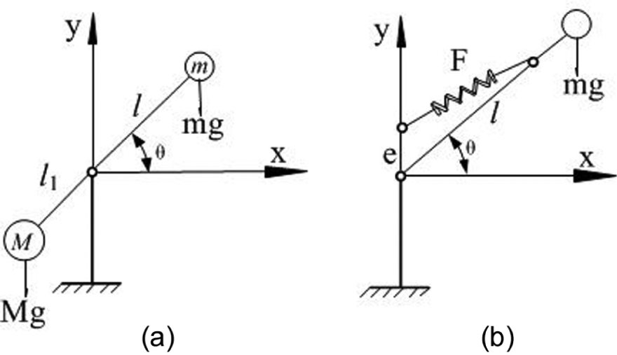
Gravity balance principle: (a) counterweight balance and (b) spring balance.
Counterweight method is the most simple and feasible method to solve the problem, but counterweight body is often limited by workspace. And when using counterweight method to balance a large mass, the moment of inertia and holding power will be clearly increased after the completion of gravity moment balance, which will deteriorate the performance of mechanism’s starting, braking, and rapidity of respond.
This article developed relatively simple but effective mathematical models of multi-needle puncture prostate using nonlinear spring–damper model; based on Automatic Dynamic Analysis of Mechanical Systems (ADAMS) or dynamics module, displacement simulation for prostate is performed. Aiming at the limitation of human body structure space and seed implant needle insertion path, a RRT-type cantilever articulated robot with three-dimensional (3D) TRUS navigation is designed. An elastic balance mechanism is designed to realize the complete balance of cantilever weight. Based on ADAMS or dynamics model, static drive torque simulation of 2-revolute (2R) tandem cantilever structure is performed. Finally, we manufacture the robot prototype and make verification experiment to the cantilever balancing device, and the experiment results provide evidence that elastic balance mechanism can realize the complete balance of cantilever weight, improve the fluctuation in the amplitude value of driving torque, and increase its operation stationary of seed implantation robot system.
A novel seed implantation mechanism for prostate brachytherapy
Multi-needling stability mechanism analysis
Figure 3 shows prostate deformation and displacement in single-needle puncturing during prostate brachytherapy procedure under ultrasound images in vivo; after puncture, we can observe that the prostate average displacement is approximately 10 mm (the distance between two white dotted lines). Thus, it is very difficult to place the needle at the desired targeted position because of factors such as tissue deformation and movement.

Prostate deformation and displacement with single-needle puncturing: (a) prepare puncture, (b) during puncture, and (c) after puncture.
Podder et al. 11 developed a multichannel robotic system for permanent seed implant in prostate. In vitro experiment with a soft material phantom, the results show that this system possesses potentially several advantages such as reduced target displacement, reduced edema, and less operating time as compared to single-needle insertion technique. In order to verify the effectiveness of multichannel robotic system, we established mathematical models of multi-needle puncture prostate and simulation method. There are three kinds of commonly used soft tissue deformation modeling method: constitutive equation, the finite element method, and the quality spring model. DiMaio and Salcudean 17 used the finite element method analysis of soft tissue deformation. Although the accuracy is higher but low in calculation efficiencies, so it cannot be used for real-time applications. Tanaka et al. 18 came up with a quality spring–damping equivalent model. The above-mentioned methods are for single-needle puncture mathematical modeling of soft tissue and are rarely for multi-needle mathematical modeling of soft tissue. So, we have also developed relatively simple but effective mathematical models. The mathematical models of multi-needle puncture prostate were established using nonlinear spring–damper model as shown in Figure 4.

Mathematical models of multi-needle puncture prostate: (a) nonlinear spring–damper model and (b) displacement analysis.
The assumption of the soft tissue follows nonlinear spring–damper behaviors, so the force equilibrium equation in the x-direction of prostate can be expressed as follows
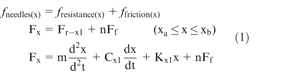
where Fx is the multi-needle insertion force, Fr-x1 is the resultant resistive force, Ff is the friction force, m is the mass of the prostate, Cx1 is the damping factor, Kx1 is the spring constant, t is the needle insertion time, x is the prostate displacement, and n is the number of needles.
The friction force Ff is given by needles for prostate tissue, and the equilibrium equation is as follows

where μ is the coefficient of friction, Fc is the normal compressive force on the needle, d is outside diameter of the needle, s is the insertion depth, and
From formulas (1) and (2), the force equilibrium equation in the x-direction of prostate can be expressed as follows

Although prostate tissue follows nonlinear spring–damper behaviors, in order to simplify the simulation process, we need to assume nonlinear spring and damper coefficients as a constant. In order to simulate the process of needle inserted force, we assume puncture force corresponding to an approximate step function, that is,
Specific simulation parameters.

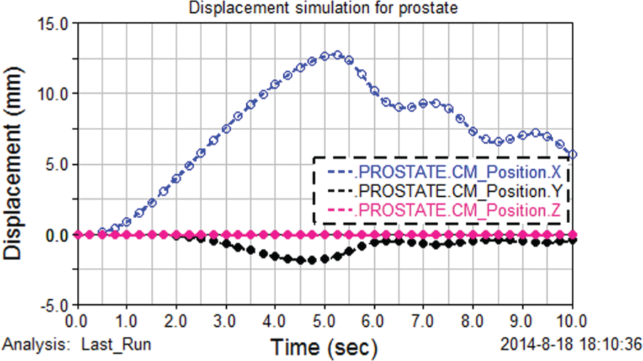
Displacement simulation for prostate.
Seed implantation articulated robot
Measurements of the available workspace for a robot were made in the operation room (OR) during actual brachytherapy procedures (Figure 6). The knowledge gleaned from these measurements was useful in designing a compact robotic system that would work efficiently in the severely constrained workspace in the OR.

Workspace for robotic insertion of brachytherapy needle: (a) front view and (b) top view.
Consider under the limited space, in order to improve robotic motion performance, we design a 6-DOFs seed implantation articulated robot as shown in Figure 7. And the positioning device consists of RRT-type cantilever, parallelogram structure composed by connecting rods. It can keep seed implant device’s end parallel pass through marked points in the guide template.

Seed implantation articulated robot structure.
Although this design will not only transfer the quality of the small arm to the base but also reduce the quality and rotational inertia of the cantilever and improve the robot’s response speed and load weight ratio. But we need to add 1 kg weight load (seed implant device) to the cantilever end. If it achieves positioning operation at this time, the cantilever gravity, rotational inertia, and soft tissue resistance will cause fluctuation in the amplitude of driving torque. Thus, it will deteriorate the cantilever’s motion performance and may affect seed placement accuracy.
Joint torque balance mechanism analysis
If the load torque is greater than the driving torque, the cantilever may drop causing accident. Thus, we can only choose greater power and torque of motor, which will inevitably cause the robot structure to become larger. Combined with the cantilever and the positioning device’s weakness, we need to redesign the torque balancing device to balance the cantilever weight.
In order to simplify the study analysis, we assume that gravity torque of big arm is equal to the equivalent cantilever gravity torque. During positioning operation, the intersection angle will change between big arm and the horizontal direction, as a result big arm changes according to the cosine law (as shown in Figure 8) by the following expression


Counterweight scheme for balance of big arm.
where G is the equivalent cantilever weight, L is the distance from the center mass of cantilever to the revolution joint of big arm, and θ is the intersection angle between the big arm and the horizontal direction.
If we want to balance out this moment of force, we need to input a backward moment of force according to the regular variation of cosine. Based on the above analysis, a kind of horizontal elastic balance mechanism is designed, as shown in Figure 9. This balance structure keeping the horizontal spring deformation in accordance with the cosine rule, so its counterbalance also follows the cosine law.

Horizontal spring balance mechanism.
During balancing of cantilever joint torques, the horizontal arrangement spring (spring stiffness is k1) is shaped into a cosine law of motion L1cosθ, the horizontal elastic force is k1L1cosθ, and distance form force vector to arm vector is L1sinθ (for fulcrum O2). Thus, the balance moment produced by the horizontal spring is as follows

In this case, we can make the equivalent cantilever weight torque equal to the horizontal spring balance torque, that is

Simplifying formula (6), the calculated results
But from the motion analysis of balance mechanism, the variation regulation of distance between slide block and the arbitrary point in the length of sideway is


Elastic balance mechanism with double spring.
Simplifying formula (7), the calculated results
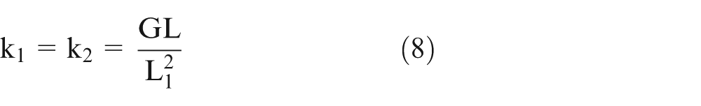
where k1 is the stiffness coefficient of horizontal spring, k2 is the stiffness coefficient of vertical spring, and L1 is the distance from the action point on big arm applied by balance force to the revolution joint of big arm.
From the above calculation, we know that the balance mechanism of double spring can eliminate the angle variation θ existed in balance. If we want to achieve the gravity torque balance of big arm, we only need to select spring with suitable stiffness coefficient according to the structure dimensions of cantilever. Formula (8) provides theory reference for selecting the stiffness of spring.
Joint torque balance mechanism simulated analysis
If the spring balance mechanism has to achieve perfect balance of cantilever weight, we need to select a reasonable spring stiffness k1 and the initial length of the spring. In order to verify balance effect, static drive torque simulation of 2R tandem cantilever structure is performed. We chose output torque of the joint drive motor as the evaluation parameter, the specific simulation parameters are shown in Table 2.
Specific parameters of the simulation.

Cantilever moment balance simulation under the vertical load
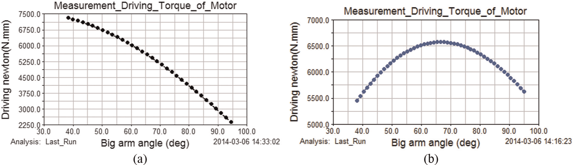
Figure 11 shows the simulated images of output torque of big arm drive motor in pace with the intersection angle of big arm under vertical load (1 kg). From Figure 11(a) and (b), we can obtain that when the intersection angle of big arm is increased from 40° to 95°, the cantilever moves to the left. Because arm of force decreases cantilever gravity torque, the output torque of the driving motor will gradually be reduced. By comparing Figure 11(a) and (b), we can calculate simulated results that the average output torque of big arm drive motor reduces by about 14.21%, and fluctuation amplitude value (standard deviation) of output torque reduces by about 43.84%.

Under vertical load of 1 kg, the output torque of big arm drive motor (a) without double-spring balance mechanism and (b) with double-spring balance mechanism.
Cantilever moment balance simulation under the horizontal load
Figure 12 shows the simulated images of output torque of big arm drive motor in pace with intersection angle of big arm under horizontal load (1 kg). When the needle punctures prostate tissue that will produces a horizontal leftward resistance. Figure 12(a) shows that when the intersection angle of big arm is increased from 40° to 95°, the cantilever moves to the left, and the output torque of big arm drive motor will gradually be reduced. Figure 12(b) shows that when the intersection angle of big arm is increased from 40° to 75°, since the spring in a compressed state is a resistance, the output torque will increase instead. The intersection angle is increased from 70° to 95° since the spring in the stretched state produces a counterweight according to the double-spring balance structure.
Under horizontal load 1 kg, the output torque of big arm drive motor (a) without double-spring balance mechanism and (b) with double-spring balance mechanism.
By comparing Figure 12(a) and (b), we can calculate simulated results that the average output torque of big arm drive motor reduces by about 12.27%, and the output torque of big arm drive motor reduces by about 78.42%. Under the two kinds of loads, the average output torque reduces nearly, but in the horizontal load, the fluctuation amplitude value of output torque of big arm drive motor reduces distinctly.
Experimental analysis
In order to further validate consistency of simulation and experiment results, we have achieved the cantilever weight balance experiment procedure. Figure 13(a) shows the seed implant robot prototype; Figure 13(b) shows the double-spring balance structure. This article using quantitative experiment method analyzes driving torque changes according to the intersection angle of big arm from 40° to 95°.

Torque balance experimental system: (a) seed implantation articulated robot prototype and (b) double-spring balance mechanism.
Experimental method
First step. Disassemble the big arm speed reducer, driving motor of big arm, and double-balance spring; then mount indexing plate on rotary center of the big arm and adjust the intersection angle between the big arm and the horizontal direction to 45°; and, finally, keep the big arm in stationary state using compact force gauge (CFG+ 200 N), fixed to the vertical load (10 N) on the cantilever end.
Second step. Increasing the tension slowly; records data of compact force gauge (CFG+ 200 N) when the big arm began to turn; then use this approach to record the experimental data every 5° until intersection angle between the big arm and the horizontal direction is 95°, and, finally, import the recorded data to the computer by the serial port RS232 of CFG+ 200 N.
Third step. Readjust the intersection angle between the big arm and the horizontal direction to 45°, using another compact force gauge (CFG+ 200 N) retain horizontal force (10 N) fixed from start to finish, repeat step 2.
Fourth step. Readjust the intersection angle between the big arm and the horizontal direction to 45°, keep the big arm in stationary state using compact force gauge (CFG+ 200 N), fixed to the vertical load (10 N) on the cantilever end, at the same time, using another compact force gauge (CFG+ 200 N) retain horizontal force (10 N) fixed, repeat step 2.
Fifth step. Considered accidental human operator error caused experiment, repeat steps (1)–(4) three times, and then record the average of the measurement results.
Experimental data analysis
From the above quantitative experiments, we obtain a torque balance effect image (Figure 14) under three kinds of loads (vertical load 1 kg, horizontal load 1 kg, and vertical and horizontal loads each 1 kg).

Torque balance effect image. The two black line charts are torque balance effect image under vertical load 1 kg; the two red line charts are torque balance effect image under horizontal load 1 kg; the two navy blue line charts are torque balance effect image under vertical and horizontal loads each 1 kg; solid point line chart are torque balance effect image with elastic equilibrium mechanism; and hollow point line chart are torque balance effect image without elastic equilibrium mechanism.
The torque balance effect image shows that after installing elastic balance mechanism, during the increase in the intersection angle of big arm from 40° to 95°, and under three kinds of loads, the maximum driving torque reduced to 1800 N mm. (1) Under vertical load of 1 kg (from two black line charts), the average driving torque decreases by about 862.4 N mm, and the fluctuation amplitude value of driving torque reduces by about 852.7 N mm. (2) Under horizontal load of 1 kg (from two navy blue line charts), the average driving torque decreases by about 637 N mm, and the fluctuation amplitude value of driving torque reduces by about 978.5 N mm. (3) Under vertical and horizontal load each 1 kg (from two navy blue line charts), the average driving torque decreases by about 905.5 N mm, and the fluctuation amplitude value of driving torque reduces by about 802.5 N mm.
The above experimental results showed that double-spring balance system really balances out the corresponding cantilever gravity. As expected, the experimental results as compared with simulation results, the average driving torque increases by about 3.7%, and the fluctuation amplitude value of driving torque increases by about 5.9%. Results may be caused by the following reasons, such as on the assumption that the ideal working conditions (not take into account friction et al.), and as well as man-made experimental deviation.
Conclusion and outlook
This article discusses that several new mechanisms may be used to improve needle placement at the desired target and stability movement performance of seed implantation robot. We performed preliminarily some simulation and experiments to evaluate multi-needling stability mechanism and joint torque balance mechanism. We have also developed relatively simple but effective mathematical models of multi-needle puncture prostate using nonlinear spring–damper model; based on ADAMS or motion module, displacement simulation for prostate is performed. Simulation results indicate that the multi-needle puncture mechanism could reduce prostate displacement in the y- or z-direction.
According to using measurements of the available workspace in the OR during actual brachytherapy procedures, we have developed a 6-DOFs seed implantation articulated robot for prostate brachytherapy treatment with radioactive permanent seed deposition. Through the torque balance analysis of RRT-type cantilever of seed implantation articulated robot, under two kinds of loads (vertical load of 1 kg, horizontal load of 1 kg), output torque of big arm drive motor is analyzed without elastic balance mechanism and with double-spring balance mechanism using the same parameters and movement.
Simulation result shows that it will be better under the condition that intersection angle of big arm is in the range of 45°–90°. Double-spring balance mechanism largely reduces the influence of output torque of big arm drive motor resulted from the cantilevered deadweight of seed implantation articulated robot. Under the two kinds of loads, with double-spring balance mechanism, the average output torque of big arm drive motor reduces by about nearly 13%, but in horizontal load, the fluctuation amplitude value of output torque reduces distinctly. Thus, we have achieved the cantilever weight balance quantitative experiment procedure. The experimental results validate the rationality of the design of the elastic balance mechanism. This also realizes perfect balance of cantilever deadweight within the working range of seed implantation articulated robot without the precondition of increasing moment of inertia. In the future, we will further study change rules of this seed implantation articulated robotic speed, acceleration with this double-spring balance mechanism.
Footnotes
Academic Editor: Seung-Bok Choi
Declaration of conflicting interests
The authors declare that there is no conflict of interest.
Funding
This research was supported by the National Natural Science Foundation of China (grant nos 51075105, 51205093), Doctoral Scientific Fund Project of the Ministry of Education of China (grant no. 20122303110006), Heilongjiang Province Education Bureau Project (grant nos 12521081, 12531122), and Harbin Science and Technology Innovation Researchers Project (grant no. 2011RFXXS075).