
Abstract
Knee-stretched walking is considered to be a human-like and energy-efficient gait. The strategy of extending legs to obtain vertical center of mass trajectory is commonly used to avoid the problem of singularities in knee-stretched gait generation. However, knee-stretched gait generation utilizing this strategy with toe-off and heel-strike has kinematics conflicts at transition moments between single support and double support phases. In this article, a knee-stretched walking generation with toe-off and heel-strike for the position-controlled humanoid robot has been proposed. The position constraints of center of mass have been considered in the gait generation to avoid the kinematics conflicts based on model predictive control. The method has been verified in simulation and validated in experiment.
Introduction
Most biped walking studies use a knee-bent posture to avoid the problem of singularities. Nevertheless, knee-bent walking is not only extremely unnatural but also high cost in terms of power consumption compared with human walking. 1,2 Knee-stretched walking is more human-like and energy-efficient than knee-bent walking, 3 though the problem of singularities arises. It can also achieve longer strides than knee-bent walking. 2 To date, knee-stretched walking has been extensively discussed in passive walking studies, 4 –7 but few studies about knee-stretched walking have been conducted in fully-actuated humanoid robots. 8 Recently, utilizing whole-body dynamics control on the fully-actuated torque-controlled robot is a big trend in this field, but these methods based on accurate modelling and their validity have not been confirmed on the position-controlled robot yet. 9,10 Therefore, the position-based method is still worth being researched for its fundamental simplicity and robustness. 11
Knee-stretched walking with fully-actuated position-controlled robots has been achieved by exploiting special mechanisms to avoid the problem of singularities. Ogura et al. developed a pelvis with an extra roll joint and a foot with a toe joint. 12 –14 Handharu et al. designed a foot with both toe and heel joints. 15 Sadedel et al. equipped active toe joints on robot feet. 16 All of them solve the problem of singularities by increasing the degrees of freedom (DOFs) of mechanisms to increase the control authority. Unfortunately, this increases manufacturing costs and control difficulties. To avoid these shortcomings, some studies have solved the problem of singularities by predefining vertical center of mass (CoM) trajectory and then controlling dynamics with the zero moment point (ZMP). 17,18 Nonetheless, an appropriate vertical CoM trajectory is always computationally complex since it must carefully avoid singularities.
To overcome the difficulty of complex vertical CoM trajectory planning, the strategy of fully extending the robots’ legs within a limited knee range of motion was introduced. With such strategy, an appropriate vertical CoM trajectory can easily be obtained, and the neighborhood near singularity point is avoided in the limited range of motion. Some of the researchers that utilized this concept failed to exploit the toe-off and heel-strike. 19 –22 Toe-off and heel-strike are important characteristics of human-like walking, and they are helpful to enhance step length and energy efficiency. 23 –25 Kajita et al. first designed the knee-stretched walking pattern with toe-off and heel-strike in the spatial domain and then transformed the pattern into a time-domain trajectory based on an optimized CoM velocity trajectory. 26 Successful long-stride knee-stretched walking was accomplished with humanoid robotics platform HRP-2Kai, 27 and yet this method is necessary to sacrifice speed tracking accuracy to ensure walking stability because of the trade-off between ZMP tracking accuracy and speed tracking accuracy in the cost function of CoM velocity optimization. Fortunately, this problem does not exist if gait generation is designed in the time domain. Miura et al. designed the walking pattern in time-domain and utilized toe-off and heel-strike motion while forcing the legs to extend with given horizontal CoM trajectory. A stable knee-stretched walking has been accomplished on the HRP-4C robot. 28 The horizontal CoM trajectory generation of this method is based on an analytical solver. 29 In the analytical solver, the relative horizontal positions between the CoM and the midpoint of the corresponding step at the transition moment between single support and double support phases are stochastic. Nevertheless, kinematic conflicts will occur at the transition moment if using the strategy of extending legs with the stochastic relative horizontal position. Therefore, this method requires extra optimization to lower the vertical CoM generated by extending legs so as to overcome the kinematic conflicts. As a result, the optimized vertical CoM trajectory cannot guarantee the desired knee-stretched posture. Moreover, the method was based, to some extent, on extra toe links.
To solve these deficiencies, this article proposes a time-domain knee-stretched gait generation with toe-off and heel-strike for position-controlled humanoid robots. The position constraints of horizontal CoM have been considered in the proposed gait generation based on model predictive control (MPC) to avoid the kinematic conflicts while using the strategy of extending the legs. The content of this method can be summarized as follows. The CoM trajectory planning strategy of the proposed knee-stretched walking is decoupled into the sagittal plane and the lateral plane. In the sagittal plane, gait generation is further divided into vertical and horizontal CoM trajectory planning. For vertical CoM trajectory planning, legs are extended as much as possible within a limited knee range of motion using toe-off and heel-strike motion under a desired horizontal CoM trajectory. In addition, the desired horizontal CoM trajectory ensures the walking stability in the sagittal plane, and the limited knee range of motion does not include the neighborhood near singularity point. For the desired horizontal trajectory planning, the MPC is utilized to constrain the horizontal CoM position, particularly at transitions between single and double support phases. The closed-form solution of preview control 30 instead of constrained MPC is exploited to generate the lateral CoM trajectory, which accelerates computations. Moreover, available ankle trajectories planning is also provided. In the end, the presented method is validated both in simulation and in experiment on a position-controlled humanoid robot BHR6.
The rest of the article is structured as follows. The second section explicates knee-stretched gait generation with toe-off and heel-strike motion. The third section presents simulation and experimental validation. The fourth section concludes the article and suggests future research.
Knee-stretched gait generation
The CoM trajectory planning strategy is shown in Figure 1, in which the lateral, horizontal, and vertical trajectories are along x-axis (left–right axis), y-axis (forward–backward axis), and z-axis (upward–downward axis), respectively. Generally, the horizontal CoM position is equal to the horizontal position of the hip joint, the lateral CoM position is equal to the lateral position of the midpoint between two hip joints, and the CoM remains a constant height difference with the vertical position of the hip joint. Since the vertical position of the hip joint is used in inverse kinematics instead of the vertical position of the CoM, we regard these two vertical positions as equivalent in this article.

Overview of CoM trajectory planning. CoM: center of mass.
Vertical CoM trajectory planning
In vertical CoM trajectory planning, the legs fully extend, exploiting the toe-off and heel-strike, under a desired horizontal CoM trajectory; the desired horizontal CoM trajectory ensures the stability in the sagittal plane. The vertical CoM position is determined by the minimum of the maximum CoM height range that legs can achieve. If the leg has full contact with the ground, the maximum available CoM height is

where

(a) Maximum CoM height, determined by the leg that has surface contact with the ground. (b) Maximum CoM height, determined by the leg that has line contact with the ground, with heel-strike. (c) Maximum CoM height, determined by the leg that has line contact with the ground, with toe-off. Note that
To determine the minimum value of the maximum available CoM height in a single support phase (Figure 3(a)), the supporting leg is required to have full contact to maintain stability, while the swinging leg does not need to be considered (because it is off the ground). Therefore, the vertical CoM position


(a) Vertical CoM position during the single support phase. Both (b) and (c) illustrate the vertical CoM position during the double support phase. CoM: center of mass.
To determine the minimum value of the maximum available CoM height in the double support phase (Figure 3(b) and (c)), both legs must be considered. If the ankle is closer to the projection point of the current desired CoM in the sagittal plane, the corresponding leg has full contact with the ground. If the ankle is farther from the projection point of the current desired CoM in the sagittal plane, the corresponding leg has line contact with the ground. Therefore, the vertical CoM position during the double support phase can be expressed as follows

Note that this vertical CoM position must be modified when used in inverse kinematics because it is calculated with legs fully extended in the sagittal plane, that is, there may be no inverse kinematics solution if the desired lateral and sagittal CoM positions are directly combined together as the desired CoM position. In addition, the desired lateral CoM position ensures the stability in the lateral plane, and the desired sagittal CoM position ensures the stability in the sagittal plane and the knee-stretched posture.
As shown in Figure 4(a), the robot outlined in black is conducting the desired sagittal CoM position with no lateral movement. The robot outlined with gray-dotted line is conducting the desired sagittal CoM position and the desired lateral CoM position without modification of vertical CoM position, of which the maximum length limitation of the leg is violated. The robot outlined in red is conducting the desired knee-stretched motion which is stable in the sagittal plane and the desired lateral CoM position with modification of vertical CoM position, of which the maximum length limitation of the leg is satisfied. Therefore, to realize both the desired knee-stretched motion which is stable in the sagittal plane and the desired lateral CoM position, the vertical CoM position

where

(a) Illustration of the necessity of modifying vertical CoM position before inverse kinematics. (b) Geometric explanation of the modification. CoM: center of mass.
Horizontal CoM trajectory planning
The horizontal CoM position is required to be constrained, if the vertical CoM trajectory is obtained by extending the knees with toe-off and heel-strike. Otherwise, the vertical CoM position will have a sudden change at the transition moments between single and double support phases as shown in Figures 5 and 6. Time ta indicates the transition moment from a single support phase to a double support phase, and time tb indicates the transition moment from a double support phase to a single support phase. Point Mid is the midpoint between current desired footsteps during a double support phase and lies on the ground.
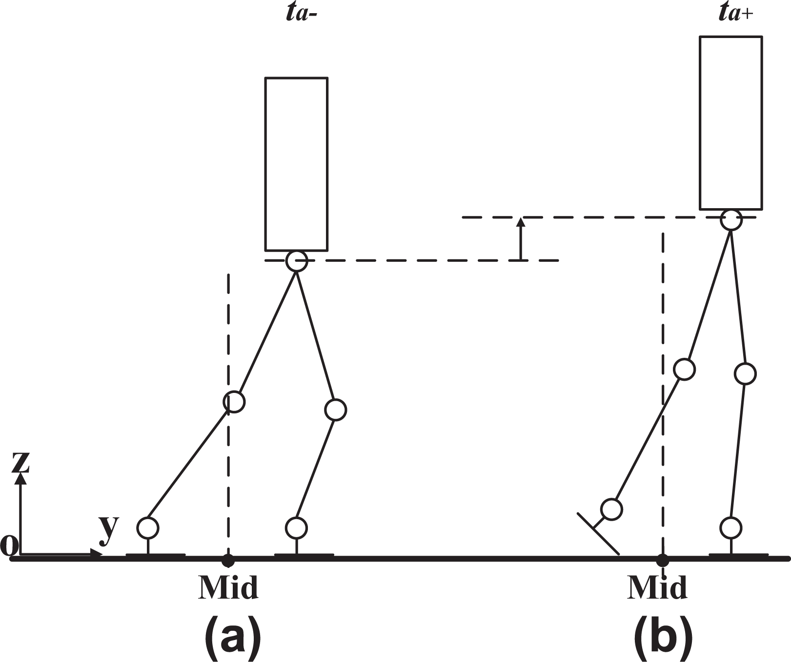
Kinematic conflict at the transition moment from single support phase to double support phase. (a) Moment just before the transition moment. (b) Moment just after the transition moment.

Kinematic conflict at the transition moment from double support phase to single support phase. (a) Moment just before the transition moment. (b) Moment just after the transition moment.
In Figure 5, the robot is at transition moment ta and its CoM position is in front of point Mid. In Figure 5(a), the hind leg is the support leg and the front leg is the swing leg. The vertical CoM is determined by the support leg. The swing leg has to bend to avoid the collision with the ground. In Figure 5(b), the vertical CoM is determined by both legs. Both legs stretch as much as possible with the help of the toe-off motion conducted by the hind leg. Therefore, the vertical CoM position will have a sudden upward change at the transition moment ta .
In Figure 6, the robot is at transition moment tb and its CoM position is behind point Mid. In Figure 6(a), the vertical CoM is determined by both legs. Both legs stretch as much as possible with the help of the heel-strike motion conducted by the front leg. In Figure 6(b), the vertical CoM is determined by the support leg. The front leg becomes the support leg, so it has to be fully contacted with the ground at once. On the other hand, the hind leg becomes the swing leg, so it has to bend at once to avoid the collision with the ground. Therefore, the CoM position will have a sudden downward change at the transition moment tb .
To sum up, the horizontal CoM position must be behind the horizontal position of point Mid at transition moment ta and in front of point Mid at transition moment tb to ensure the smoothness of the vertical CoM trajectory. The ideal horizontal CoM positions of the robot at the transition moments are shown in Figure 7. With these horizontal CoM position constraints, the robot can achieve the desired knee-stretched posture generated by extending legs during the whole walking procedure.
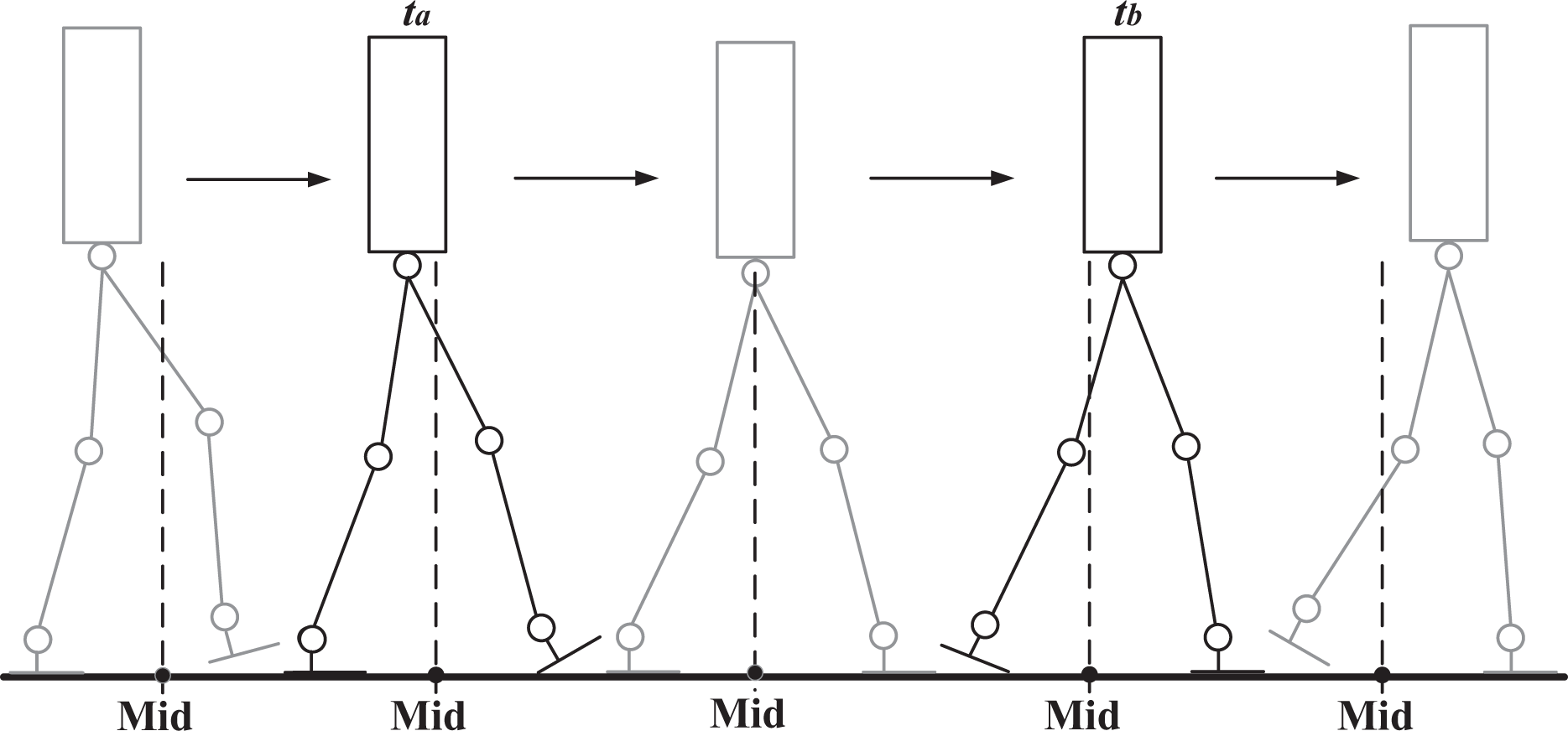
Ideal horizontal CoM positions of the robot at the transition moments (outlined in black). CoM: center of mass.
Therefore, the constraints of horizontal CoM position for the entire duration of every step can be given as follows

where
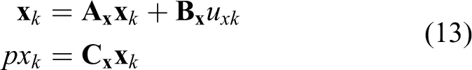
To satisfy the position constraints in equation (5), a linear constrained MPC is used to generate the horizontal CoM trajectory. The linear inverted pendulum model is selected as the simplified dynamics model for knee-stretched walking in the sagittal plane. A state vector that comprises horizontal CoM position, velocity, and acceleration of horizontal CoM is defined as follows

where T is a constant time interval. The input vector, comprising horizontal CoM jerk, is given as follows

The output vector, comprising horizontal ZMP position and horizontal CoM position, is given as follows

Thus, the discrete system dynamics is given as follows

where

where
The position constraints of horizontal ZMP and horizontal CoM are given as follows

where
The cost function minimizes the jerk of the horizontal CoM trajectory, which prevents the horizontal CoM position from diverging.
31
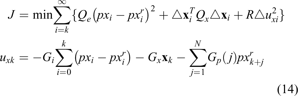
Therefore, this corresponds to solving the following constrained optimal control problem at
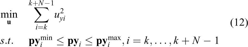
where N is the prediction horizon,
Lateral CoM trajectory planning
The same simplified dynamics model and similar state and input vectors as those used for the sagittal plane were selected for the knee-stretched walking in the lateral plane, thus the discrete system dynamics is given as follows
where
To accelerate computations, we exploited the closed-form solution of preview control
30
instead of using linear constrained MPC. Therefore, to track the lateral reference ZMP trajectory
where
Ankle trajectory planning
Ankle trajectory planning can also be divided into the sagittal plane and the lateral plane. In the lateral plane, the positions and postures of the ankles are directly equivalent to the positions and postures of desired footsteps; therefore, we only need to discuss the ankle trajectory planning in the sagittal plane.
In the double support phase shown in Figure 8(a) and (b), both robot knees are assumed to be fully extended under the desired sagittal CoM position and the desired footsteps, thus ankle trajectories in the sagittal plane can be obtained through geometric calculations. For the ankle that has full contact with the ground, the position and posture are determined by its desired footstep. For the ankle that has the line contact with the ground, if

Both (a) and (b) illustrate ankle trajectory planning in the sagittal plane during the double support phase. (c) Ankle trajectory planning in the sagittal plane during the single support phase. Note that
In the single support phase shown in Figure 8(c), the desired position and posture of the supporting ankle are determined by its desired footstep. For the position and posture of swinging ankle, we first interpolate the hip pitch joint from joint angle

which guarantees clearance between the swinging foot and the ground.
Results
Humanoid robot BHR6
The validity of the presented method is verified both in simulation and in experiment on humanoid robot BHR6. BHR6 is a 21-DOF, position-controlled robot; its appearance and configuration are shown in Figure 9. In addition, the vertical distance between the ankle joint and the sole of the foot is 0.112 m in the simulation and 0.126 m in the experiment. This vertical distance difference is because of the rubber pads that are installed under the actual robot feet to absorb the landing impact.
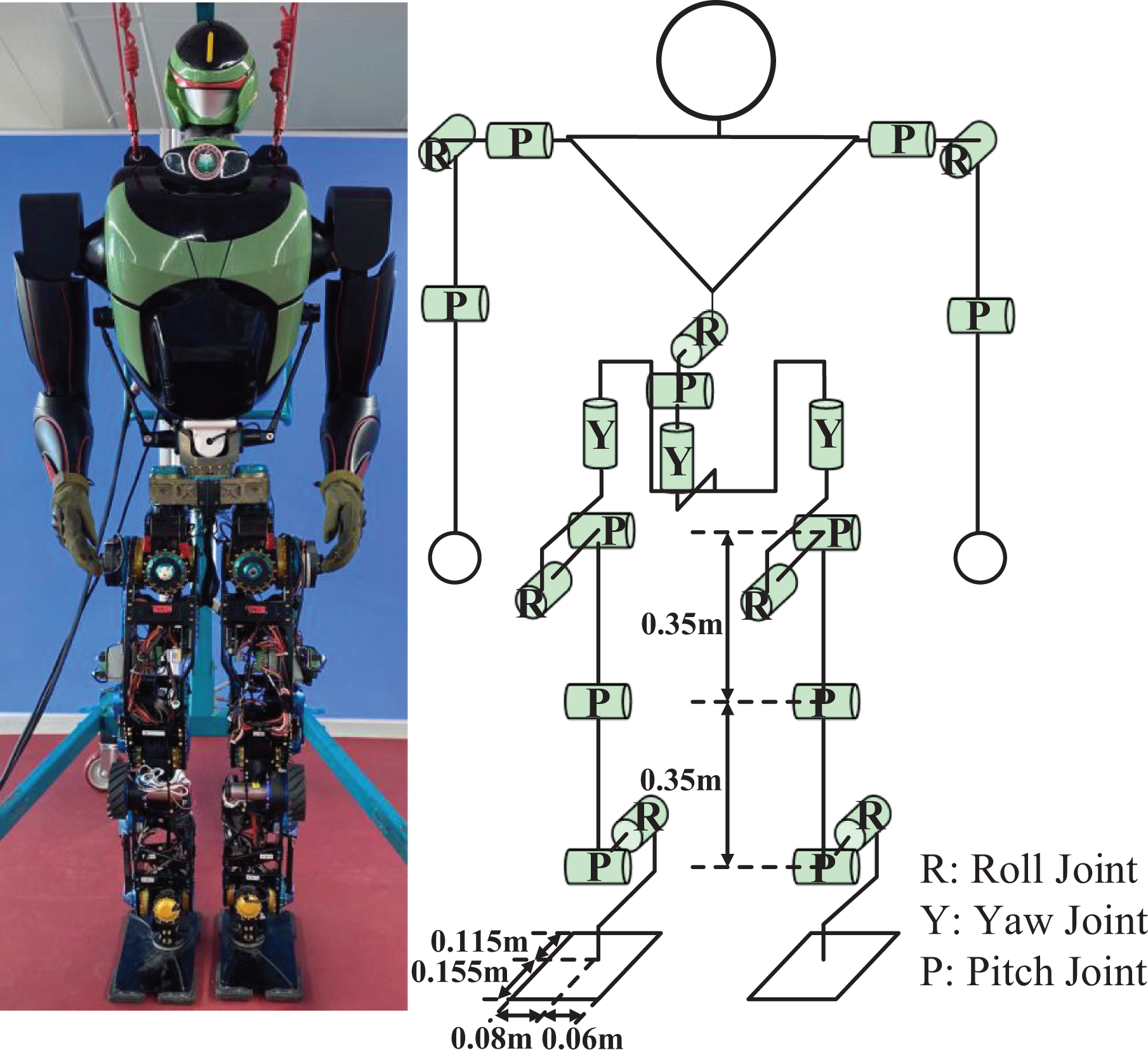
Appearance and configuration of BHR6.
Simulation
The simulated robot built-in simulation platform V-REP has the same physical parameters as the actual robot, except for the vertical distance between the ankle joint and the sole of the foot. The coefficient of static friction of the ground is set to 0.8.
A six-step knee-stretched walking with toe-off and heel-strike has been conducted and its snapshots are shown in Figure 10. Note that an ankle compliance control strategy similar to the one based on double spring damping model 32 was used in this simulation for better walking performance. The step duration was 0.6 s, the step length was 0.4 m, and the walking speed was 2.4 km/h. To avoid singularities, the maximum leg length was achieved when the angle of knee joint is −4°. For better stability, the sagittal ZMP position constraint in equation (11) becomes

where
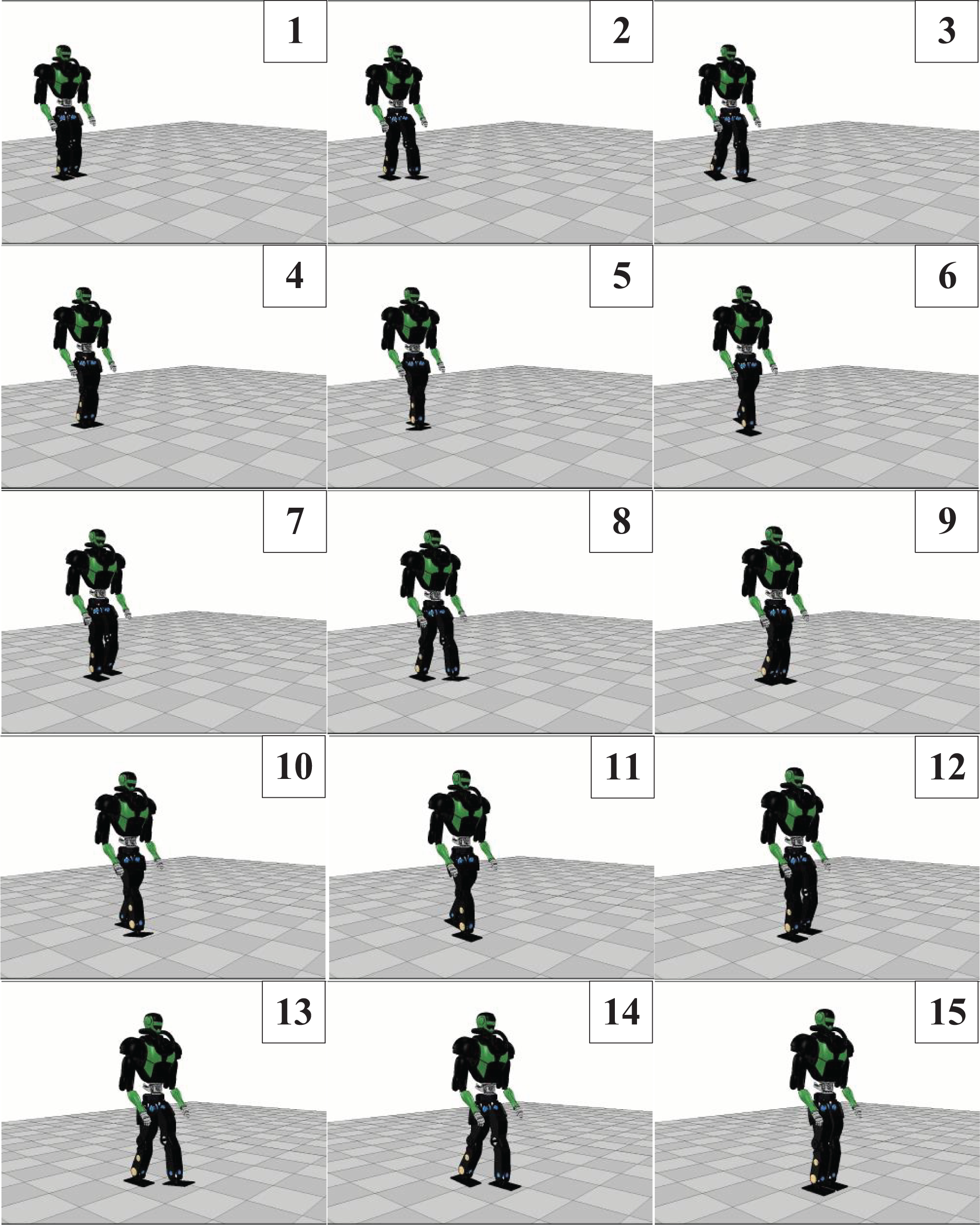
Snapshots of knee-stretched walking with toe-off and heel-strike in the simulation.

Desired CoM trajectories used in the simulation. CoM: center of mass.

Desired ZMP trajectories used in the simulation. ZMP: zero moment point.
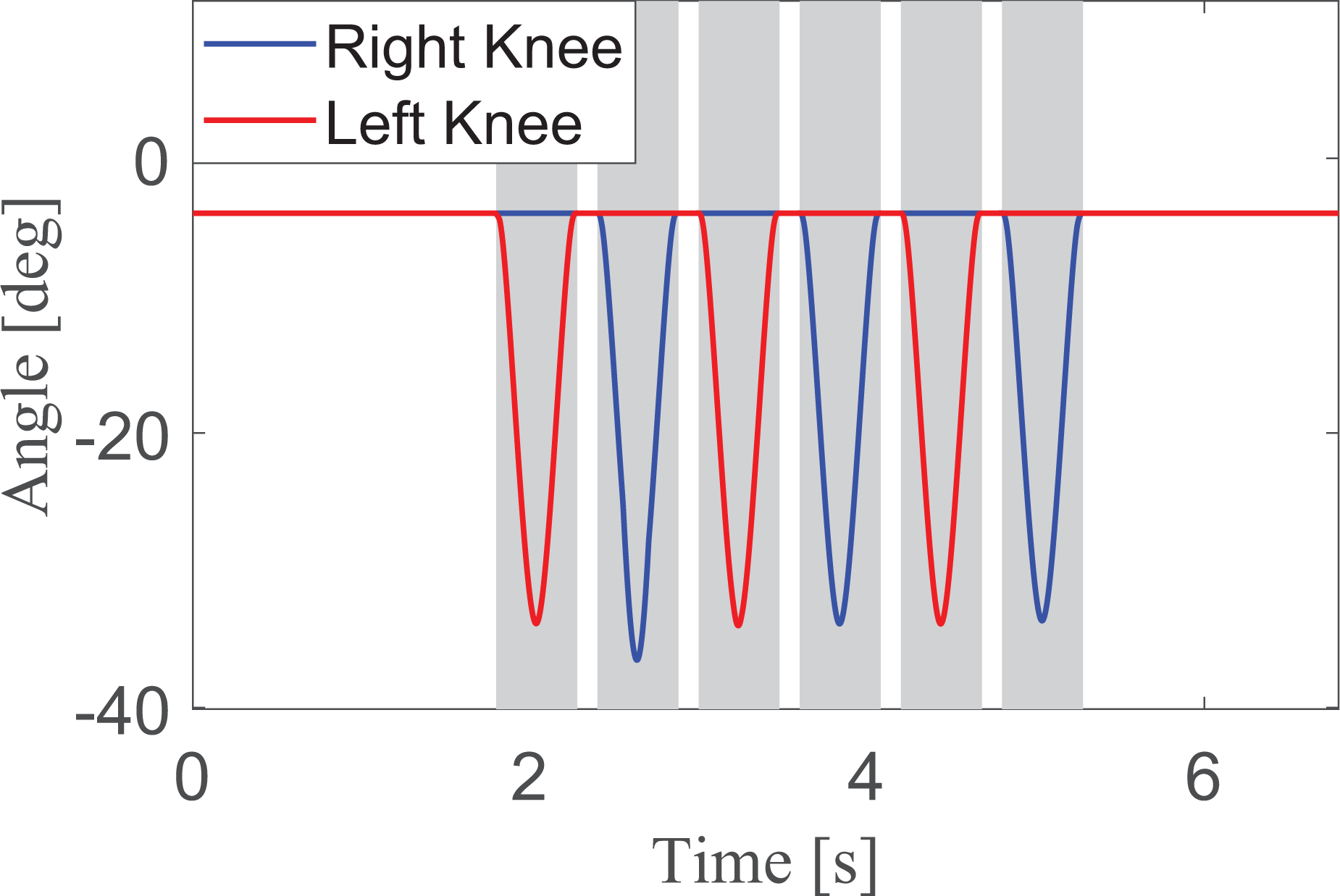
Desired knee joints trajectories used in the simulation. The gray background areas represent single support phases while the white background areas represent double support phases.
The ZMP trajectories measured during knee-stretched walking are shown in Figure 14. Both sagittal and lateral ZMP trajectories are within the boundaries of the range of the robot support polygons; therefore, the results demonstrate that stable knee-stretched walking with toe-off and heel-strike has been achieved, verifying the proposed gait generation in simulation.
ZMP trajectories measured in the simulation. Blue line: measured ZMP trajectories. Solid black line: reference ZMP trajectories. Dotted black line: boundaries of support polygons. (a) ZMP trajectory measured in the lateral plane. (b) ZMP trajectory measured in the sagittal plane. ZMP: zero moment point.
Moreover, a comparison of energy consumption between a six-step knee-stretched walking and six-step knee-bent walking is also conducted in simulation, and the result is shown in Figure 15. The step duration and the step length are also 0.6 s and 0.4 m, respectively. The Figure shows the energy consumption of the robot right leg while walking. As shown in the result, the energy consumption of the robot right leg in knee-stretched walking has been largely reduced compared with that in knee-bent walking.

Energy consumption of robot right leg while walking in the simulation. Red line: energy consumption of the leg in knee-stretched walking. Blue line: energy consumption of the leg in knee-bent walking.
Experiment
Snapshots of a four-step knee-stretched walking experiment with toe-off and heel-strike motion are shown in Figure 16. Note that a torso compliance control strategy similar to trunk position compliance control 33,34 was used in this experiment for better walking performance.
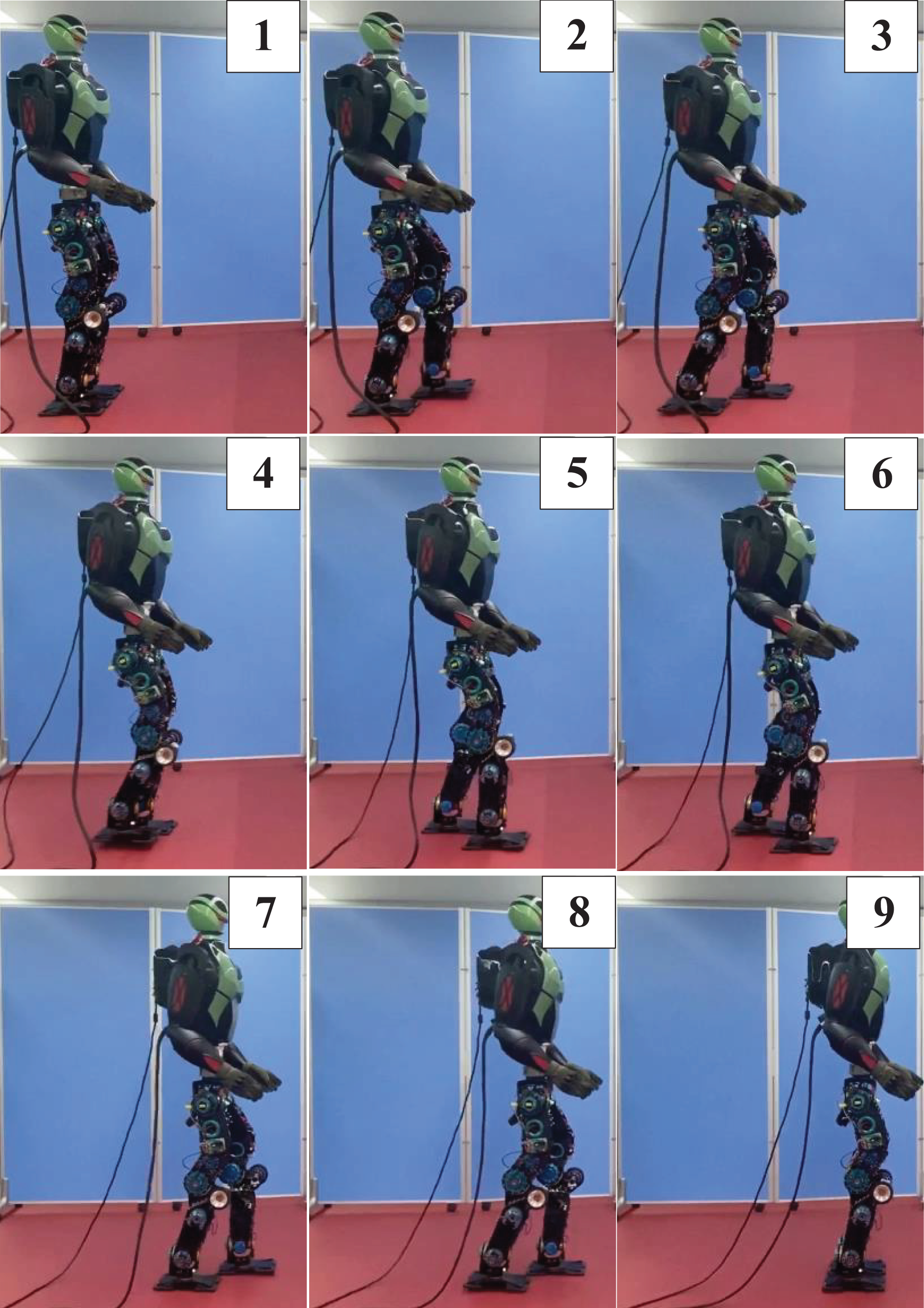
Snapshots of knee-stretched walking with toe-off and heel-strike in the experiment.
The step duration was 0.8 s and the step length was 0.25 m, thus the walking speed was 1.125 km/h. To avoid singularities, the maximum leg length is achieved when the angle of knee joint was −4°. For better stability, the sagittal ZMP position constraint in equation (11) becomes

where

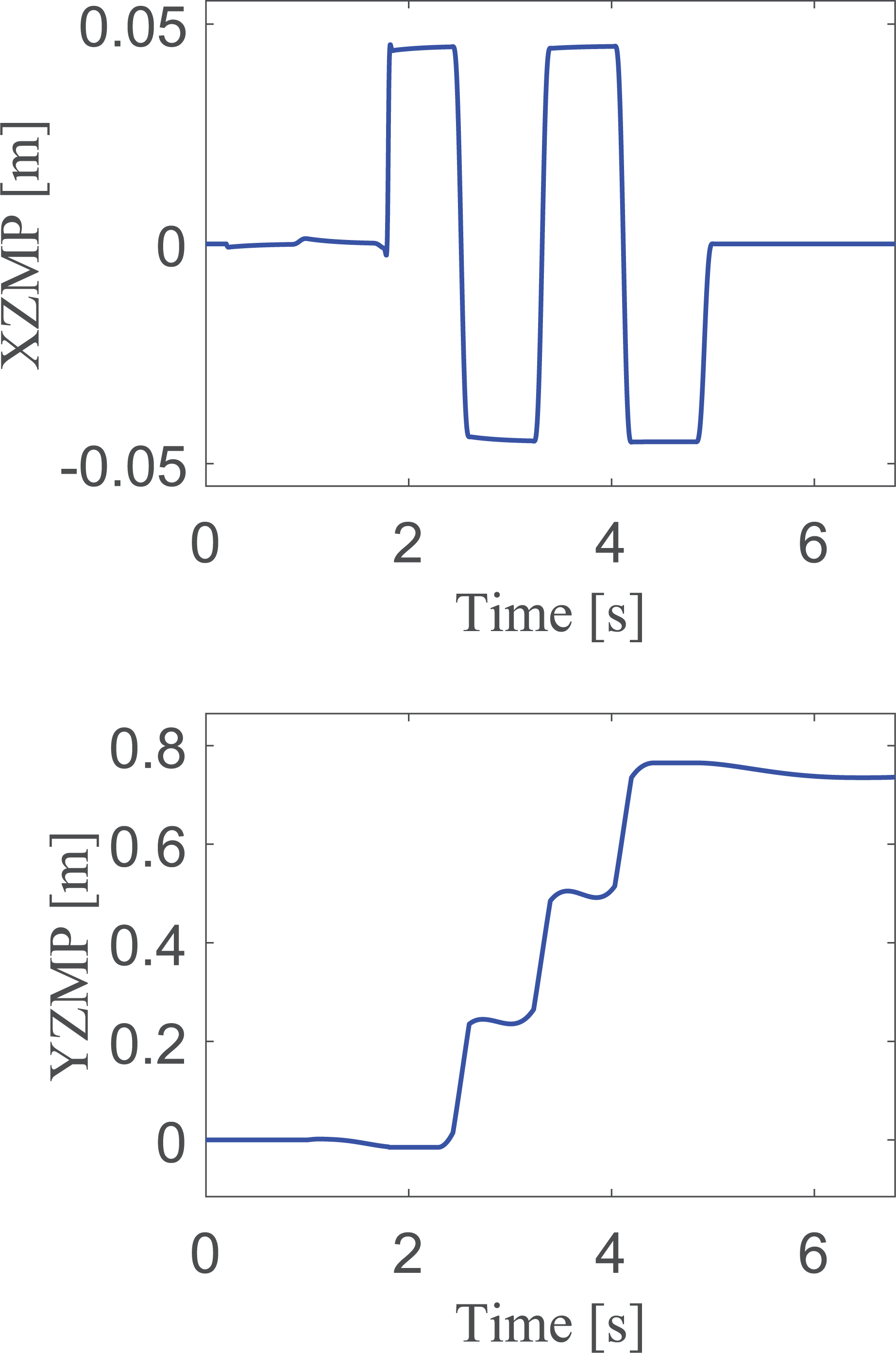
Desired CoM trajectories used in the experiment. CoM: center of mass.

Desired knee joints trajectories used in the experiment. The gray background areas represent single support phases while the white background areas represent double support phases.
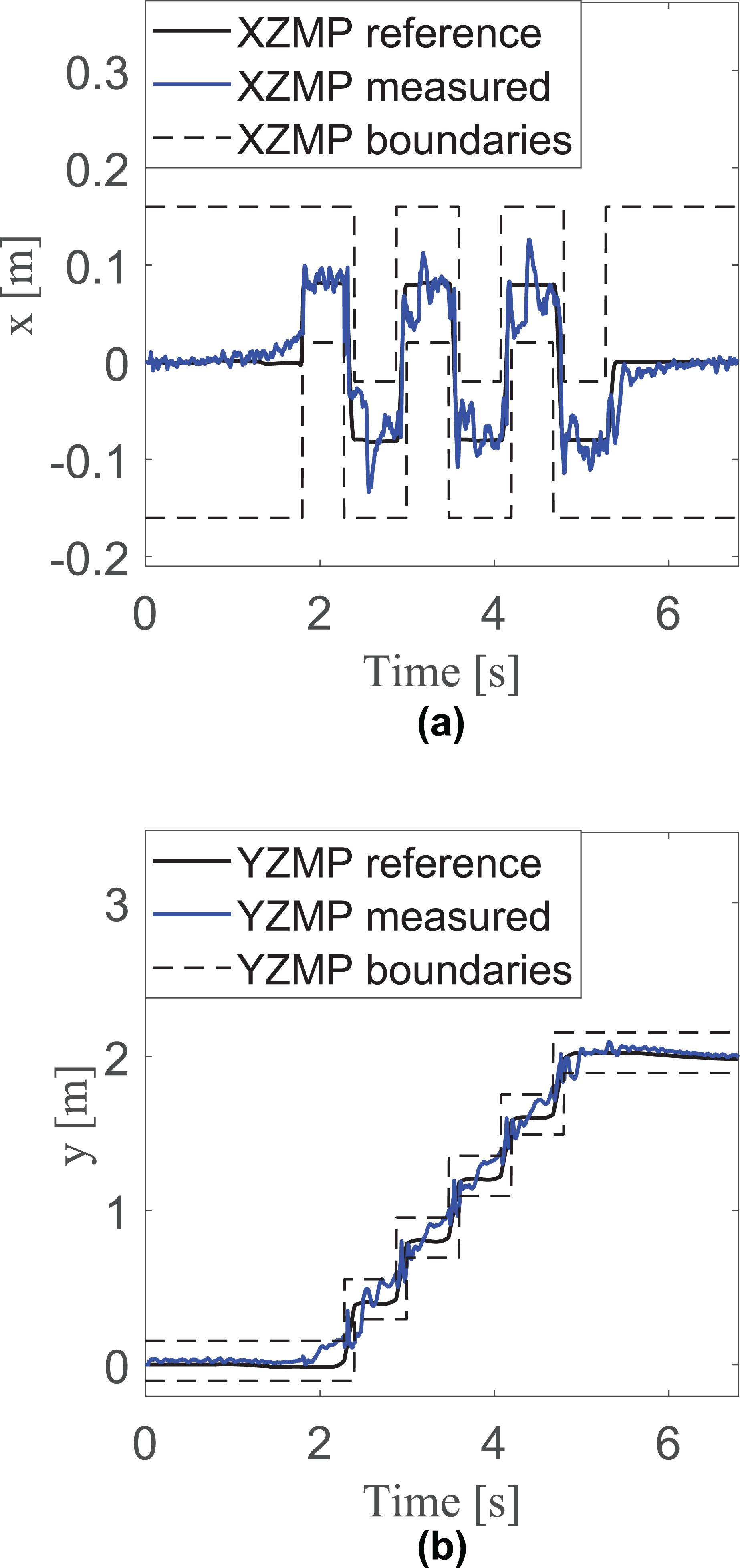
ZMP trajectories measured in the experiment are shown in Figure 20. Although the ZMP values around time 5 s exceed the boundaries, which are mainly caused by the modeling errors and joint flexibility, the subsequent ZMP values return within the boundaries due to the utilized compliance controllers. The results still show that successful knee-stretched walking with toe-off and heel-strike is fulfilled by the position-controlled humanoid robot BHR6, thus the validity of the proposed method in experiment is confirmed.

ZMP trajectories measured in the experiment. Blue line: measured ZMP trajectories. Black line: boundaries of support polygons. (a) ZMP trajectory measured in the lateral plane. (b) ZMP trajectory measured in the sagittal plane. ZMP: zero moment point.
The walking speed and number of steps in the experiment were less than those in the simulation. The performance of stretched-knee walking with toe-off and heel-strike will be improved in future experiments.
Conclusion and future plan
Knee-stretched walking is generally considered as a natural and energy-efficient type of walking. This article focused on realizing a knee-stretched walking with toe-off and heel-strike on a position-controlled humanoid robot. The contributions of this article are summarized as follows:
Time-domain gait generation for knee-stretched walking with toe-off and heel-strike for position-controlled humanoid robots is proposed. The horizontal CoM trajectory with position constraints is generated by MPC to ensure that the desired knee-stretched posture generated by the strategy of extending legs can be obtained.
The validity of the proposed method has been confirmed both in simulation and in experiment. The position-controlled humanoid robot BHR6 achieved successful knee-stretched walking with toe-off and heel-strike at a speed of 2.4 km/h in simulation and at a speed of 1.125 km/h in experiment. The energy consumption of the knee-stretched walking generated by the proposed method is reduced compared with the knee-bent walking, which is confirmed in simulation.
In the future, the performance of knee-stretched walking with toe-off and heel-strike motion in experiment is intended to be improved, and some online footstep adjustment strategies are intended to be integrated to allow the robot walk through terrain with knee-stretched posture or maintain stable knee-stretched walking under large external disturbance.
Footnotes
Declaration of conflicting interests
The author(s) declared no potential conflicts of interest with respect to the research, authorship, and/or publication of this article.
Funding
The author(s) disclosed receipt of the following financial support for the research, authorship, and/or publication of this article: This work was financially supported by the National Natural Science Foundation of China under Grant nos 91748202, 61973039, and 61903038, and by “111” Project under Grant B08043, and by Beijing Natural Science Foundation under Grant 3192029.