
Abstract
We designed a stable gait pattern and posture-control balance system to enable a biped humanoid robot to maintain balance and avoid falling when walking on uneven ground or slopes. In this study, we first examined the problem of gait generation and the balance of a humanoid robot and then proposed a posture-control balance system using the inertial sensors of a gyroscope and accelerometer to sense the tilt angle of the robot according to the environment. To process the data obtained by the sensors, the mean filter was applied to eliminate the noise in the data, and the complementary filter was used to properly combine the data from both the gyroscope and accelerometer. The system further modifies the gait and posture of the robot based on the results obtained through a fuzzy system to attain the angle of balance and stabilization. A robot with an open platform was used to test the implementation of the proposed algorithm, and the experimental results demonstrated that the robot could successfully maintain balance when walking uphill and downhill on uneven surfaces. Moreover, because only one parameter needs to be adjusted when applying the balance-control system, the system can be easily extended to any related humanoid robot.
Introduction
With the rapid development of robots in recent years, the interaction between people and robots has become more common, and humanoid robots must be able to walk in various real-life environments, including hills and bumpy roads. Smashing Robotics, a website that displays robotics information has summarized that the most commonly manufactured humanoid robots are the following: dynamic anthropomorphic robot with intelligence–open platform (DARwIn-OP, ROBOTIS OP), DARwIn Mini (ROBOTIS Mini), NAO Evolution, Pepper, Romeo, HUBO 2 Plus, HOVIS Series Robots, RoboThespian, and iCub. 1 For robots such as DARwIn-OP or NAO Evolution that have legs instead of wheel platforms, enabling balance when walking is the most critical aspect in the design process and determines humanoid robot performance. Small humanoid robots are mostly used in educational, research, and entertainment domains because they are relatively manageable, expandable, and affordable. However, because of their small space, a limited number of devices, such as sensors or motors, can be placed on these robots. Therefore, achieving stability with these limitations is the most critical aspect in the design of robot walking methods. Besides, some humanoid robot competition, such as FIRA (Federation of International RoboSports Association) requires the robot to be able to walk on uneven ground. For example, in the lift and carry event, the robot needs to step up and walk on irregularly-shaped color boards with coins spread randomly on them. Also, in the marathon event of FIRA, the robot needs to walk through outdoor uneven, even tilt ground. The environments of these two events are shown in Figure 1. How to enable a robot to walk on uneven or a little hilled ground as well as flat ground is an issue for the design of humanoid robots in the competition. Therefore, this paper is motivated to design a robot with the ability to walk through an uneven floor or even a small hill while walking forward to fulfill the needs in the FIRA competition.

Robot walking on an uneven floor in the competition.
To achieve stability of the walking process of the humanoid robot, several gait patterns have been designed that enable humanoid robots to walk on both flat and uneven surfaces. One of the most commonly used criteria for achieving humanoid robot gait stability is zero moment point (ZMP). 2 ZMP is defined as the point where the total of horizontal inertia and gravity forces equals zero. When the robot achieves the ZMP, the reaction of the foot of the robot to the floor compensates for the dynamics caused by the movement of the robot, and the dynamic balance of the robot is maintained. 3
To obtain the ZMP, the center of mass (COM) 4 of the robot is calculated. Therefore, either simulation calculations or force sensors equipped on the feet of the robot are required. A fuzzy algorithm 5 or fuzzy algorithm with a Kalman filter 6 has been used to adjust the gait parameter according to the ZMP position or trajectory to achieve robot stability. Jeong et al. 7 and Guadarrama-Olvera et al. 8 calculate whether the ZMP is within the support polygon to change the footstep position and time to keep balance. Mummolo et al. 9 dealt with the effect of different contact configurations with different step lengths to maintain balance. He et al. 10 proposed an algorithm by combining a central pattern (CPG) with a foot rotation indicator (FRI) to establish the mapping function between the COM within the support polygon to keep balance. Furthermore, several machine learning methods have been proposed and applied to achieve robot walking stability. For example, reinforcement learning,11,12 Q-learning, 13 and particle swarm optimization methods 14 have been applied to enable the adjustment of gait parameters to obtain stable walking gait. These machine learning methods have also been applied to sloped surfaces to improve the humanoid robot walking stability on sloped terrain. 15 Silva et al. 15 proposed a robotic gait correction system based on a reinforcement learning method that enabled the robot to remain upright and stable on an approximately 20° inclined board. Li et al. 16 used an accelerometer and force sensor to design a robot for climbing stairs.
However, the calculation of the ZMP for each step is time-consuming for a small humanoid robot with limited system resources and calculation speeds. Furthermore, a pressure sensor or force sensor is required to calculate the ZMP. Thus, robot stability is difficult to achieve when a pressure sensor is installed under the feet of the robot.
Force sensors have been substituted with gyroscopes or accelerometers integrated with a feedback control system to adjust the gait pattern of the robot to maintain stability. Baltes et al. 17 used two gyroscopes with feedback control to adjust robot stability. However, only simulation results were reported, and the method was not implemented on a robot. Lu et al. 18 and Luat and Kim 19 used a set of force sensors to calculate the ZMP and gyroscope and accelerometer to estimate the inclination of the robot to keep the balance for push recovery. Ha et al. 20 proposed a stable gait generation system for a robot based on coupled oscillators. The system used oscillator parameters and sensor data related to the feedback controller to ensure robot stability without calculating the ZMP; the system achieved stable walking on flat surfaces.
To avoid complex ZMP calculations during the robot’s walk, the posture adjustment or posture modification method has been proposed in several studies to ensure the robot adapts to uneven terrains. Nenchev and Nishio, 21 Aftab et al., 22 and Kim et al. 23 proposed ankle and hip strategies for balance recovery of the humanoid robot on the basis of the acceleration data measured during impact and the adjustment. In this case, the detection was confined to the sagittal plane. Yılmaz et al., 24 Ito et al., 25 Zhang et al., 26 and Joe et al. 27 proposed a posture-control algorithm that adjusts the orientation of the pitch angle of the upper body to adapt to different slope walking surfaces and ensures robot stability.
Similarly, Ito et al. 28 proposed an actuation mechanism for a biped robot that reduced the number of actuators in the hip joint structure without sacrificing the ability to walk adaptively on slopes. An inertial measurement unit, accelerometer, and a gyroscope have often been placed in the robot’s chest to measure the body’s tilt posture on uneven terrains.29–32 Kuo et al. 33 designed a fuzzy logic controller to generate appropriate offset angles on the corresponding joints to ensure the body’s tilt posture can be adjusted appropriately to attain stability. In most cases, robots walk forward; therefore, only the motion on the sagittal plane of the robot is discussed. Sun and Roos 34 proposed a group of neural network controllers to regulate the sagittal and lateral motion of the robot’s gait in the presence of an unknown terrain while maintaining stability. In control algorithms, the fuzzy logic controller, 29 neural network control, 33 and particle swarm optimization controller 34 were designed to adjust the parameters of the gait pattern to generate stable walking postures for the robots.
In theory, it is possible for a robot to maintain balance on uneven surfaces and slopes by using only built-in sensors. We attempted to achieve this condition in this study. We proposed a posture-control balance system that can recognize the environment using a gyroscope and accelerometer and adapt the robot to the environment by modifying the robot’s posture. To recognize the environment, gyroscope and accelerometer sensors were integrated into the system, and the mean filter and complementary filters were combined to preprocess the sensor data without the Kalman filter. This approach requires more steps to obtain appropriate filter parameters. After noise was eliminated from the sensor data using filters, the robot could recognize that a surface was uneven, uphill or downhill, through the tilt angle calculated from the sensor. Then, the gait pattern parameter was adjusted to alter the posture of the robot to achieve self-balancing. The method was verified and demonstrated on a DARwIn-OP 35 humanoid robot through several experiments. The rest of the paper is structured as follows: The hardware structure of the humanoid robot is introduced in Section II, and the gait pattern and balance control algorithm are proposed in Section III. The experimental results and conclusion are presented in Sections IV and V, respectively.
System hardware
The humanoid robot used in this study was a DARwIn-OP manufactured by ROBOTIS. The structure of a DARwIn-OP is presented in Figure 1. The height of the robot is 45.5 cm, which satisfied the requirement of the humanoid league Kid size of RoboCup and FIRA that a robot is less than 90 cm. The robot operates at 1.6 GHz with an Intel Atom Z530 (32 bit) and on-board 4 GB flash SSD and has 20 actuators, three-axis gyroscopes, and three-axis accelerometers in the body as well as a webcam in the head. The related motor ID of the humanoid robot is presented in Figure 2.

DARwIn-OP Motor ID positions.
Proposed algorithm
Gait pattern
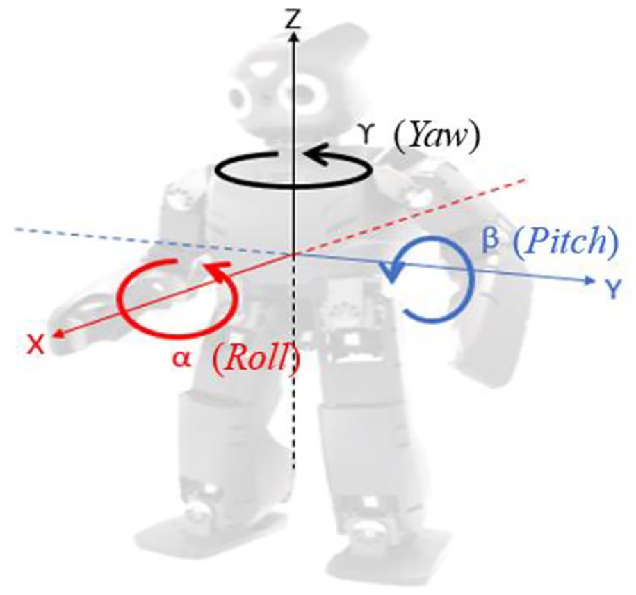
The complete gait cycle can be divided into five stages, and the front view of the humanoid robot in each stage is presented in Figure 3. The first stage starts with the double support phase (DSP) of the foot before the robot starts walking. The second stage involves the robot lifting its left foot and entering the single support phase (SSP). Then, as the robot’s left foot falls to the ground, it enters the DSP again for stage 3. In stage 4, when the right foot of the robot is lifted, the robot enters the SSP again. Finally, after the robot’s right foot falls back to the ground and enters the DSP, a gait cycle of the robot is completed. Next, we defined the three coordinate axes of the robot and the corresponding rotation direction, as presented in Figure 4. The X-axis is the front/rear direction of the robot, the Y-axis is the left/right direction of the robot, and the Z-axis is the up/down direction of the robot. Here, α is the rotation angle of the robot on the YZ plane and is called the roll, β is the rotation angle of the robot on the XZ plane and is called the pitch, and γ is the rotation angle of the robot on the XY plane and is called yaw.

Front view of gait cycle.
Robot walking direction and rotation angle.
To control the gait pattern of the humanoid robot, the parameters of the three axes and the corresponding direction of rotation were set. The foot trajectory of the robot consists of three parts. The first part is the movement track of the foot (indicated by the subscript m), and the second part, indicated by the subscript s, is the swing trajectory during walking. The last part is the robot’s initial position, or offset, indicated by d. Equation (1) expresses the total movement of the foot in the X-axis direction during walking and is the superposition of the X-axis movement trajectory, which includes the swing trajectory, the movement track, and the starting offset.

where

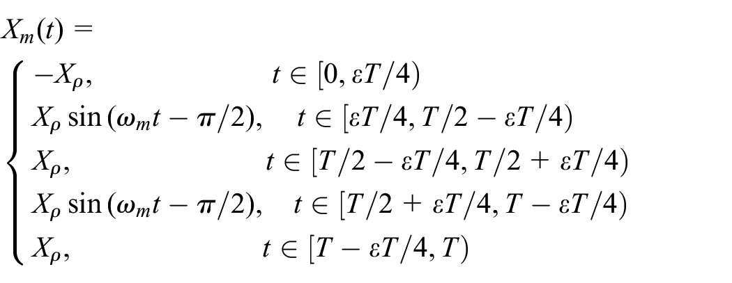
In (1), movement and swing amplitudes are defined as Xρ and Xμ, the angular velocities of move and swing as ωm and ωs, the DSP ratio as ε, and the period of each gait as T. The reason for such definition is that the walking pattern can be considered as two oscillators, 20 one is the balance oscillator activates in the entire walking period which is Xs. The other is the movement oscillator is restrained during Double Support Phase (DSP) which is Xm. A similar design concept is used for Y-axis and Z-axis. Hence, the total movement trajectory of the foot in the Y-axis and Z-axis are in (2) and (3), respectively. Equations (4), (5), and (6) express the rotational offset of the foot in the α, β, and γ directions, respectively. The offset in three axes and rotation angles is presented in Figure 5.

where


where


The robot foot trajectories for one step are plotted in Figure 6(a)–(c) to represent the movements with all parameters defined in (1), (2), and (3), respectively. The red line indicates the left foot, and the blue line denotes the right foot.

Robot offset in the three axes and rotation angles.

Total foot trajectories of the robot for one step.
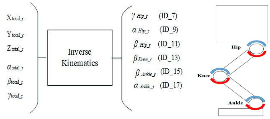
Then, the total trajectory in three axes and three rotational directions were separated into the left foot and right foot. For each foot, we summarized the relationship between the gait pattern of the foot and its corresponding motor angle. The correspondence of the right foot is presented in Figure 7 and that of the left foot in Figure 8. The corresponding procedure was conducted by substituting the parameters of the foot—Xtotal_r, Ytotal_r, Ztotal_r, αtotal_r, βtotal_r, and γtotal_r—into the calculation of inverse kinematics36–39 to obtain the angles of the hip in α, β, and γ directions, the knee in β direction, and the ankle in α and β directions. The formulas for the forward and inverse kinematics of the robot are omitted in this work.
Right foot gait generation and related angles.

Left foot gait generation and related angles.
Parameters related to balance
After we design the gait pattern shown in Section A, the robot may still not be able to keep balance if the environment it walks through is not flat. Therefore, a balance control system is proposed to enable the robot to walk on uneven ground or hills. In the gait balance system proposed in this paper, we defined three parameters, namely the offset parameter of the ankle in the pitch direction βd, the acceleration g, and gyroscope angular velocity ω. Since the situation is set to be walking forward, only the x-direction (the sagittal plane) for the acceleration and gyroscope is considered. The acceleration and gyroscope angular velocity involved in this system were both confined to back and forth direction. The values obtained from the accelerometer and gyroscope are in the range between 0∼1023, which indicates the data from the accelerometer and gyroscope are represented with 10-bit resolution. Table 1 shows the related parameters obtained from the accelerometer and gyroscope. The system accessed the AdcR from the sensors and calculated the related parameters ω and g by (7). In Table 1, the AdcR is the value obtained from the sensor, Vref is the operating voltage for the sensor, Vzero is the 0g voltage level for accelerometer, and the voltage that the gyroscope outputs when it is not subject to any rotation. The data from the accelerometer and gyroscope are in x, y, z axis. Therefore, the results of R form (7) are gx, gy, and gz, and ωx, ωy, and ωz for accelerometer and gyroscope, respectively.

The parameters of accelerometer and gyroscope.

To obtain a smoother signal and avoid the noise, the mean filter was applied to preprocess the data from the accelerometer and gyroscope. The mean filter is described in (8), where N is the size of the mean filter, x[n] is the input, and y[n] is the output.

The mean filter is a sliding-window spatial filter that assigns the output value with the average of all the values in the window, as shown in Figure 9. Since N, the range of the window of the mean filter, is the minimum number of data required to obtain the average value, n is defined as greater than or equal to N–1 in (8). Different sizes of the mean filter were used to verify that the noise of the signal can be eliminated and smoothed, as depicted in Figure10. In Figure10, the original signal is plotted in red, and the filtered result is plotted in green. When N is very small, the signal is easily affected by the noise, but when N is very large, the signal is smothered, and the characteristics of variation are lost. Compare Figure 10(a) and (b), the green line in Figure 10(b) is smoother than that of Figure 10(a). Therefore, the size of the mean filter was selected to be 10 to avoid the noise and retain the original tendency of slightly left-right shaking while walking.

Both data from the accelerometer and gyroscope were preprocessed by the mean filter to obtain stable data called gm and ωm, respectively. Then, the Euler angle transformation was performed to transform the acceleration into the tilt angle θaccel, the related relationship between acceleration and Euler angle is shown in (9). Since robot situation is set to be walking forward, only the x-direction (the sagittal plane) for the acceleration and gyroscope is considered. Hence, the pitch value in (9) is the tilt angle θaccel.

Sliding-window of the mean filter with N = 10.

Different sizes of mean filter results of acceleration data.
The angular velocity from the gyroscope was integrated to obtain the tilt angle θgyro. Then, the complementary filter was applied to combine the tilt angles θaccel and θgyro. The block diagram of the parameter processing in tilt angle calculation is presented in Figure11. The complementary filter has two different filters, one is the low-pass filter, and the other is the high-pass filter. The reason for choosing a complementary filter instead of the Kalman filter is the simplicity of the complementary filter. 39 In the related work about the complementary filter and Kalman filter,40,41 theoretically, the Kalman filter is more accurate than the complementary filter. However, the Kalman filter has three parameters that need to be tuned, and the complexity makes the difficulty of the Kalman filter to achieve a more accurate result. Hence, the complementary filter is used in this work for simplicity.

Robot tilt angle calculation.
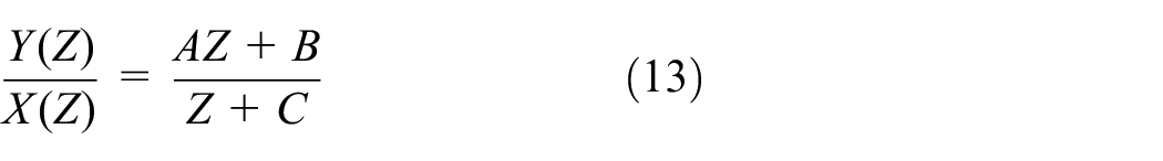
The transfer function of the low-pass filter in the discrete Z transform is shown in (10), and the time domain equation of (10) is in (11). Then, the equation of the low-pass filter is rewritten in (12), where a and b are constants. Similarly, the transfer function of the high-pass filter in discrete Z transform is shown in (13), and the time domain equation of (13) is in (14). Then, the equation of the high-pass filter is rewritten in (15), where c, d, and e are constants.


The high-frequency noise of the accelerometer data is filtered by the low-pass filter in (16), which is similar to (12), and the input of the low-pass filter is θaccel, and the output is θac. The low-frequency noise of the gyroscope data is filtered by the high-pass filter in (17), which is similar to (15), and the input of the high-pass filter is θgyro, and the output is θgc. The selective filter comes from the distinct characteristics of accelerometer sensors having long-term reliability and the gyroscope sensors having short-term accuracy. Finally, the inclination angles of the two sensors after filtering were combined to obtain a more accurate tilt angle θs, as presented in (18). θs varies in different environments, such as ground or uneven surface. The weight factor φ of the complementary filter 40 in (19) was calculated from the response time of the low-pass filter and high-pass filter τ and the sampling time of gyroscope dt. Referred to the result in, 42 the τ is 0.49 seconds and dt is 0.01 seconds; thus, 0.98 is obtained for φ.


where

After discussing the values of acceleration and gyroscope angular velocity, the next related parameter, βd, the angle of the ankle in the pitch direction is considered. The gait parameter βd affects the tilt of the humanoid robot’s posture, as shown in Figure 12. When βd equals 0, the robot is in the upright position; when βd is less than 0, the position of the robot’s body tilts forward, and vice versa. Then, we can obtain the tilt angle of the robot from the sensors, and it is represented as θr by adjusting the parameter βd from −30 to 0 and 0 to 30. The relationship between tilt angle θr and βd is plotted in Figure 13, and the related equation is described in (20). As depicted in Figure 13, the noncontinuous trend line equation for positive βd and negative βd is analyzed, and the transition point is suggested to be caused by the mechanical backlash and slight bending of the structure.

Next, the tilt angle from the sensor without adjusting the parameter βd for the robot is measured and indicated as θs, while the robot is standing upright (βd = 0) and the experiment of the robot walking on the flat ground with original gait pattern in equations (1)–(6) with βd = 0 was carried out for four times. The results are shown in Figure 14, where those of experiment 1, 2, 3, and 4 are plotted in red, green, blue, and black, respectively. We can find out that the range of the tilt angle θs obtained from the sensors is approximately varied from −8.5° to −11.5°. These values can be used to design the feedback control system about the tilt angle and gait parameter βd in the next section.
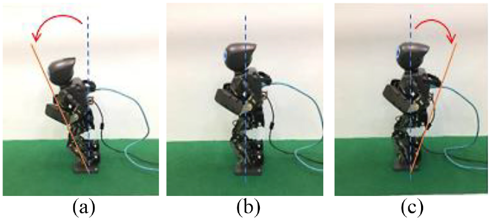
βd effect on robot balance.
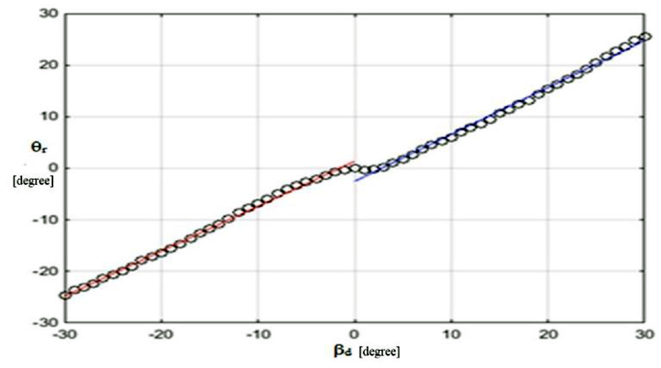
Relationship between βd and tilt angle θr of the robot.

The tilt angle θs from the sensor of the robot while walking on the flat ground.
Balance control
In general, the walking environment for a humanoid robot can be categorized as ground, upslope, or downslope. The concept of how to maintain the balance of the robot in the three types of environment is shared in common – adjusting the posture to counteract the tilt angle change. Figure 15 shows the tilt angle for the robot walking on the uphill, ground, and downhill, respectively. When the robot walks on unstable ground, uphill, or downhill, the instant tilt angle θs from the sensor is changed by the environment. In downhill, the robot will lean forward and the tilt angle from the sensor during walking is about θs≈1.8 ∼ 3.5 degrees; while in uphill, the robot will lean backward and the tilt angle from the sensor during walking is about θs≈–17 ∼–19 degrees. In the ground, the tilt angle the robot during walking is θs≈–8 ∼–11.5 degrees. The change of different tilt angles of the robot due to various walking places is shown in Figure 15. Moreover, the center of gravity of the robot should be placed on the toes when the robot is walking on uphill. Similarly, the center of gravity of the robot should be placed on the hill when the robot is walking on the downhill. Therefore, the tilt angle from the sensor according to the environment change can be classified as shown in Figure 16. When tilt angle is within Rmin and Rmax, the robot is on the ground, and a tilt angle smaller than Rmin indicates downslope, whereas a tilt angle larger than Rmax indicates upslope, as indicated in Figure 16. The values of Rmin and Rmax can be defined through experiments.

The change of the tilt angle θs of the robot walking on the uphill, ground, and downhill, respectively.

Adjustment of the posture according to the tilt angle in a different environment.
In the balance control of the humanoid robot, the feedback control was applied by adjusting the posture of the robot according to the environment. Thus, the feedback maintains the balance for the robot. Therefore, a fuzzy system is introduced to adjust the posture of the robot because the fuzzy logic offers very valuable flexibility in controlling the motors. Because the fuzzy system does not require the determined values, the less complex algorithms can be applied to obtain the parameters for controlling the gait pattern and balance of the robot. It describes all the rules fitting the system and the if-then conditions are used to control the decision-making system.


The fuzzy system uses the θd defined in (21), the difference between tilt angle θs from the sensors affected by the environment, and the posture angle θr as input. The needed adjusted tilt angle Δβd in (22) from the posture of the robot as output. The input will be fuzzied into a value within the range,0,1 and the membership functions are very low (VL), low (L), medium low (ML), medium (M), medium high (MH), high (H), and very high (VH), as defined in Figure 17. These values were obtained by repeating the experiment and machine learning process more than 30 times.
Fuzzy sets: θd∈{VL, L, ML, M, MH, H, VH}, μF is the degree of the membership function for input fuzzy set θd, {–21 −19 -16 −14 −13 −11 −7 −6 −4 −3 −1 1 5}are the values of input fuzzy set for the tilt angle θd. The membership function of Δβd is shown in Figure 18. Next, the single-input and single-output fuzzy inference system are adapted to define the fuzzy rule if… then… as follows:
Rule 1: If θd is VL, then Δβd is VL.
Rule 2: If θd is L, then Δβd is L.
Rule 3: If θd is ML, then Δβd is ML.
Rule 4: If θd is M, then Δβd is M.
Rule 5: If θd is MH, then Δβd is MH.
Rule 6: If θd is H, then Δβd is H.
Rule 7: If θd is VH, then Δβd is VH.

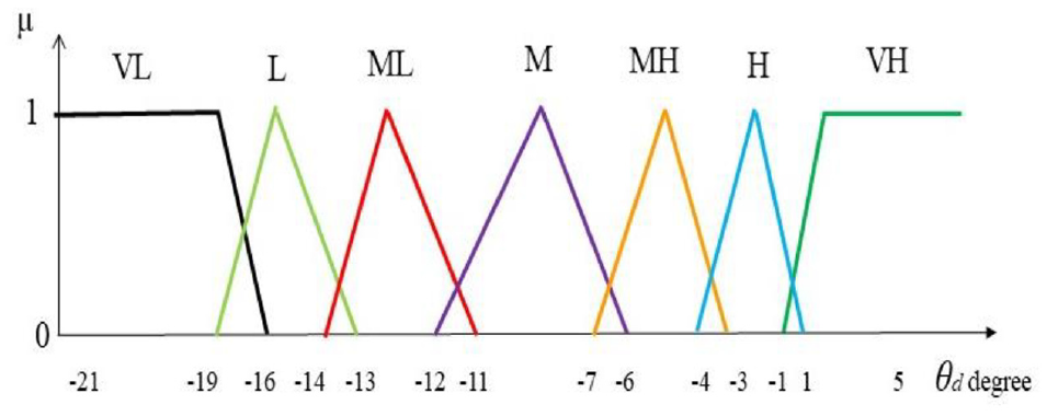
Membership function for input tilt angle θ e .
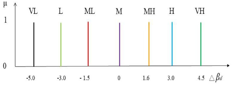
Membership function for output Δβd.
Finally, based on a fuzzy methodology, the center of gravity method for defuzzification is applied in this study to obtain the related output Δβd. In (23), Δβd* is the defuzzified value, Δβdi indicates the sample element, μ(Δβdi) is the membership function, and n represents the number of elements in the sample. Next, the new βd is obtained by applying (22) with Δβd, and the related tilt angle θr can be calculated by (20).
When the robot walks on unstable ground, the instant tilt angle θs is changed by the environment. To maintain balance during walking, adjusting the posture to counteract the tilt angle θr change caused by the environment is critical. To achieve this, the system constantly checks θd, the difference between the tilt angle of the environment and that of the posture and adjusts the posture tilt angle βd by (22), the equation applying fuzzy logic obtain the updated βd. The flow chart of the algorithm is shown in Figure 19 and the algorithm use kinematics to modify βd to control the posture of the robot and maintain balance.

The algorithm used to adjust the gait of the robot to walk on the uneven ground and slope.
Performance analysis
Walking on uneven ground
To verify the feasibility of the method proposed in Section III for the robot walking on uneven ground, we conducted the following experiment. First, we sprinkled coins on flat ground to create uneven reliefs 1.5 cm in height. Next, we compared the difference between the walk of the robot in the original gait system and the proposed balance system. The experimental results of the original gait system and modified balance system are presented in Figures 20 and 21, respectively. The robot with the original gait system fell immediately (Figure 20). By contrast, the proposed balance control algorithm assisted the humanoid robot to successfully walk on the uneven ground (Figure 21).

Original gait on uneven ground and fall.

Balance control gait on uneven ground.
The tilt angle θs from the sensors affected by the environment and tilt angle θr obtained by modifying βd from (12) throughout the experiment for original gait and balance control gait are plotted in Figures 22(a) and (b), respectively. In Figure 22(a), the tilt angle θs varies, and it rises due to uneven ground; however, θr remains at 0° throughout the experiment in the original gait pattern, which means the posture is not adjusted throughout the walking process. As a result, the robot could not react to the variation in the environment and ended up falling. The problem was fixed by changing θr to respond to the environmental variation as indicated in Figure 22(b). θr had been changed until the difference between θs and θr fell into the stable region to counteract the tilt variation caused by the environment. The continuous adjustment enabled the robot to adapt to uneven ground. In Figure 22(b), the original tilt angle of the environment θe, which is recorded from the original gait pattern experiment described above, is marked in green for the comparison between Figure 20(a) and 22(b). Then, the tilt angle, θs from the sensors is plotted in blue and it may change due to posture adjustment. The tilt angle θr obtained from (12) to adjust posture is initialed at 0 degree and marked in red. θd, the difference between θs and θr is marked in magenta. At the beginning of Figure 22(b), the values of θe and θs are the same because there is no need for adjustment while robot walking on the flat ground. However, once the balance of the robot is affected by the uneven environment, indicated as the value of θd exceeding the stable region, the difference between the tilt angle of the robot and the posture is input to the fuzzy algorithm to result in the adjustment of posture βd. Thus, the θr is changed and the value of θd falls back into the stable region, and the robot is adapted to the environment without losing balance. Meanwhile, the value of θs changes reflects the actual angle between the uneven ground and the modified body posture of the robot. From the experiment, the feasibility of the fuzzy system is verified as the comparison in Figure 22(b) indicates.
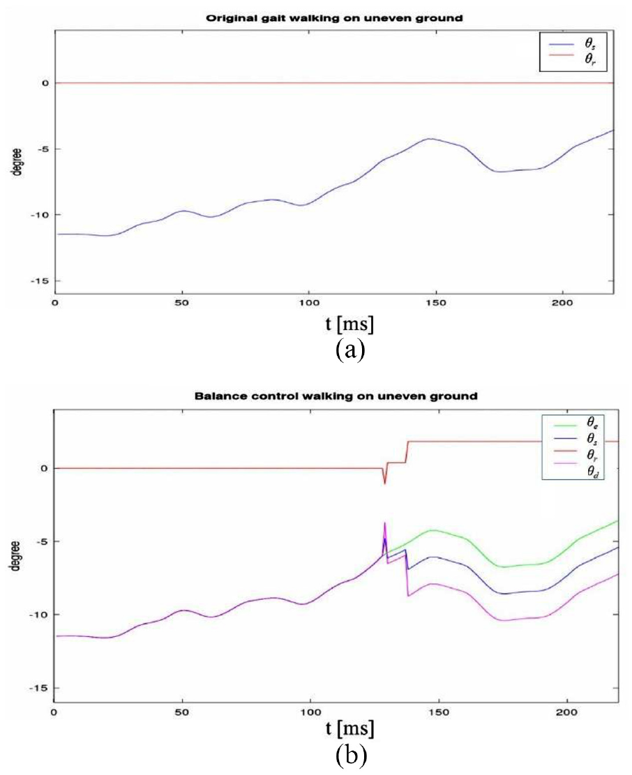
Original gait versus balance control on uneven ground.
Walking on the slope field
To verify the slope walking method proposed in Section III for the robot walking on the hills, we conducted another experiment. The experiment was divided into two parts. The first part was to have the robot walk from the ground uphill at a 15° slope, and the second part was to allow the robot to walk down the slope. The uphill and downhill experimental results are illustrated in Figures 23 and 24, respectively. Figures 23 and 24 indicate that the robot can adjust its posture according to the tilt angle obtained from the environment and accomplish the task of walking uphill or downhill without losing balance.

Walking uphill at a slope.

Walking downhill at a slope.
Conclusion
In this study, we discussed the gait generation of the DARwIn-OP humanoid robot and proposed a balance control algorithm to enhance the stability of humanoid robot gait. We attempted to maintain balance for a robot to walk on uneven surfaces and slopes by using only built-in sensors, gyroscope, and accelerometer. Hence, the inertial sensors, gyroscope, and accelerometer assisted the robot to recognize the environment, and the robot modifies its posture according to the environment to keep balance. To reduce the noise of the parameters from these sensors, the mean and complementary filters were applied and maintain the accuracy of the tilt angle of the robot obtained from the environment.
The proposed balance control system adjusted the only parameter in pitch angle of the ankle, βd, to counteract the tilt change caused by the environment and enable the robot to walk on uneven surfaces and even slopes. The experimental results demonstrated that the robot could accomplish uneven ground and uphill or downhill walking. In the future, the balance control algorithm should be applied to a large humanoid robot to demonstrate the feasibility of this study. Because the only βd should be altered and only gyroscope and acceleration sensors, which are usually built-in in a humanoid robot, are used, the proposed system can be easily applied to any humanoid robot.
Footnotes
Handling Editor: James Baldwin
Declaration of conflicting interests
The author(s) declared no potential conflicts of interest with respect to the research, authorship, and/or publication of this article.
Funding
The author(s) disclosed receipt of the following financial support for the research, authorship, and/or publication of this article: The work is supported by the Ministry of Science and Technology of Taiwan under grant no. MOST 104-2221-E-130-012 and MOST 108-2221-E-130-015.