
Abstract
The robustness of biped walking in unknown and uneven terrains is still a major challenge in research. Traversing such environments is usually solved through vision-based reasoning on footholds and feedback loops—such as ground force control. Uncertain terrains are still traversed slowly to keep inaccuracies in the perceived environment model low. In this article, we present a ground force-control scheme that allows for fast traversal of uneven terrain—including unplanned partial footholds—without using vision-based data. The approach is composed of an early-contact method, direct force control with an adaptive contact model, and a strategy to adapt the center of mass height based on contact force data. The proposed method enables the humanoid robot L
Keywords
Introduction
The research on biped robots is often motivated by their theoretical ability to traverse uneven and unstructured terrain—a scenario in which wheeled robots may fail. This intrinsic property qualifies biped robots especially for disaster response or general tasks in hostile environments. Compared to three- or four-legged systems, bipeds can turn in a smaller area and have a reduced complexity in terms of required joints. The reliability and robustness of biped robots in such environments, however, is still limited and represents a major challenge in current research.
Typically, the environment is perceived by cameras or similar sensors on the robot and safe footholds are computed based on a generated environment model. 1 –4 Although most approaches require the terrain to be flat around the contemplated footholds, recent work exists on vision-based foothold planning for irregularly protruded terrain. 5 Vision-based planning, however, greatly depends on the quality of the sensor signals. Ground height estimation errors can reach the centimeter range 1,2 and have a significant effect on the performance of the overall system. 6 To compensate for such disturbances and model inaccuracies caused by the planning of the center of mass (CoM) trajectories, fast feedback loops are typically deployed. 7 –12 For robots with torque-controlled joints, this is usually the position control of the CoM to track a desired reference trajectory based on the estimated robot state. 11,13 –15 Robots with position-controlled joints usually require an additional force-control loop to track desired ground reaction forces based on force/torque sensor data. 7,10,12
So far, uneven terrains are traversed at low walking speeds
2,5,16
–19
to keep the perception errors low and maintain stability. We focus, however, on a force-control approach for the traversal of uneven terrain at high walking speeds (
L
The article is organized as follows: First, the hardware platform L
System overview
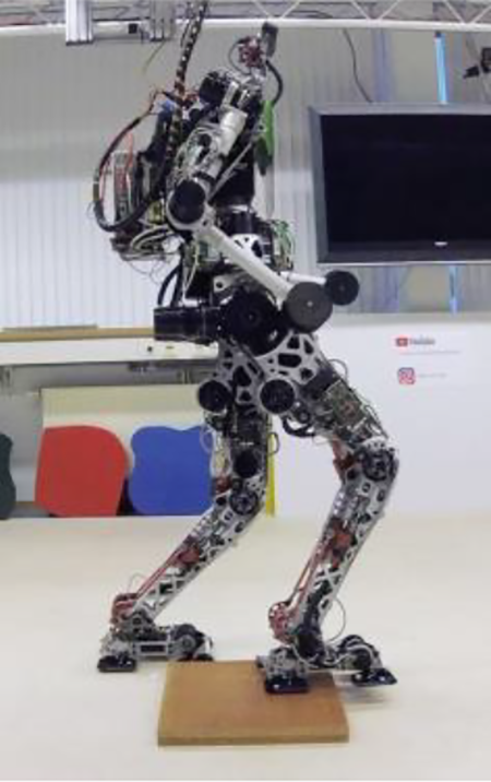
The method proposed in this article is experimentally evaluated on the biped L
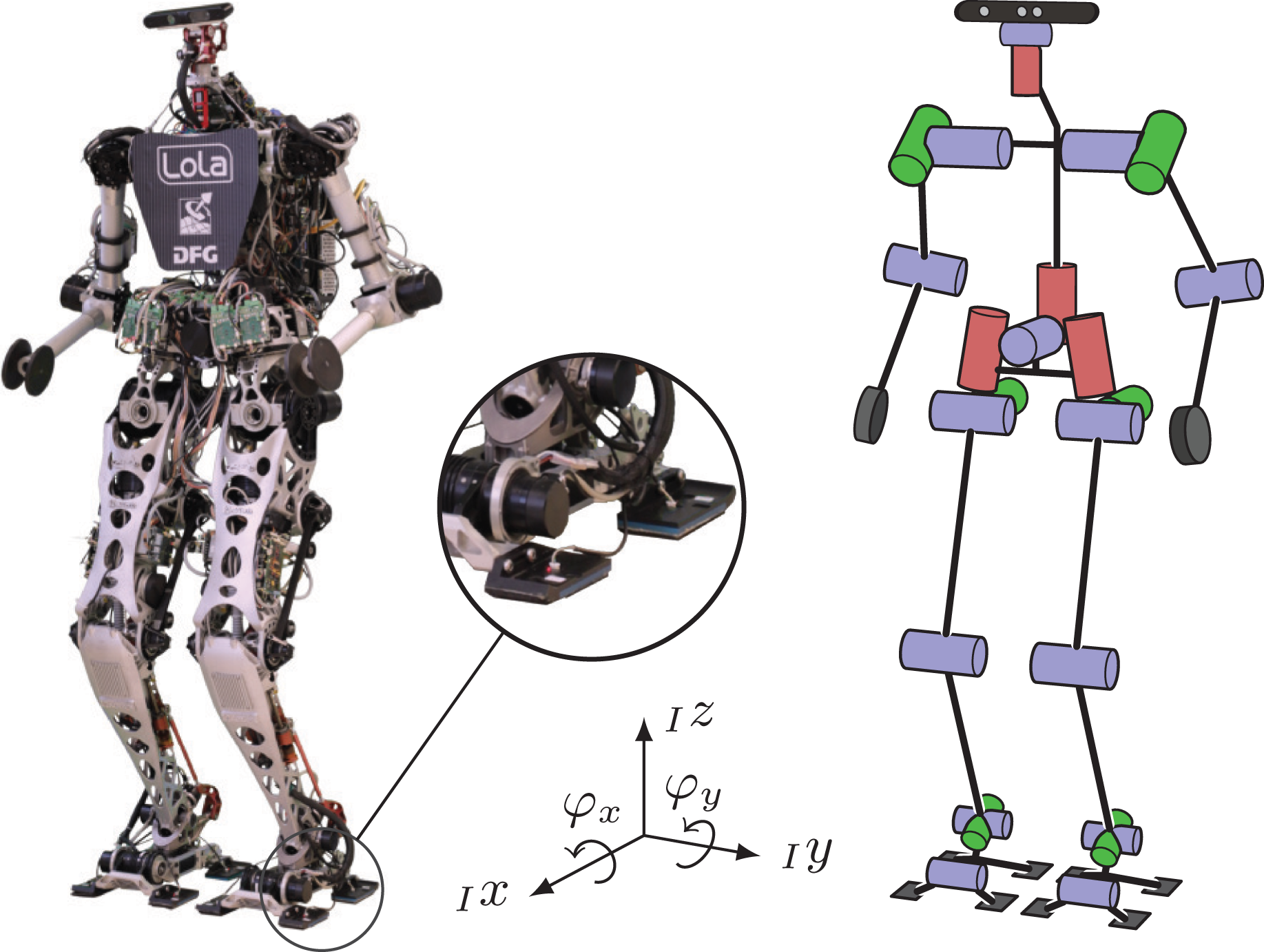
The humanoid L
Control structure
The hierarchical control structure is shown in Figure 3. User inputs given via joystick or step parameters are used to calculate an ideal walking pattern with trajectories

Overview of the hierarchical walking controller with signal flow and the different control loops.
The resulting desired forces/torques
Validation setup
The following setup conditions are used for experiments with L
Previous work on LOLA
In this section, we summarize relevant previous work on the control system of L
Balance control and force distribution
The Balance Control and Force Distribution module, see ②; in Figure 3, contains a feedback controller to stabilize the measured upper-body inclination

a torque acting on the CoM—is added to the ideal planned forces/torques
The modified forces/torques
Hybrid position/force control
The force-control approach
12
—module ③; in Figure 3—is based on a hybrid position/force-control scheme and directly modifies the ideal planned trajectories


The approach modifies the z-position of the foot’s tool center point (TCP)

with the binary selection matrix

are composed of the output of separate controllers for each foot f. Each controller is again partitioned in a force-control part
Every force controller uses an analytical, static contact-model with stiffness-matrix

The actual forces/torques on each foot

result from the whole 6-axis FT sensor data

This force controller modifies the position/orientation of the feet in contact. Getting back to the original trajectory in the swing phase requires the position-control loop

with the gain Kx, which is plugged into (5). Using this position controller, however, causes the swing-foot to end in the air or hit the ground unexpectedly in the presence of ground unevenness. That is because the positions of the feet are described relative to the CoM in the workspace: If the force controller modifies the relative position of one foot, also the other foot’s inertial position changes. This means that the position-controlled foot must follow the modifications on the vertical height of the force-controlled foot, which are caused by the control law (8). Thus, the position-control law is extended to

with the selection matrix
Early contacts
During the single-support phase, the swing foot is controlled with pure position control to allow fast adaptation for step recovery or stepping over obstacles. 4 This leads to a serious disturbance of the system, however, in the case of an undetected obstacle. With the foot in position-control mode, any vertical velocity of the foot causes high contact forces on impact. In this section, we present our approach to mitigate the unwanted effects caused by such early-contact situations. Our approach does not trigger a replanning of the CoM, and foot trajectories, but instead only modifies the currently planned trajectories to minimize the impact on the system reactively. The control concept consists of three general parts: (1) An early-contact detection logic, (2) a feed-forward controller with jerk filter, and (3) a module to handle the transition from position- to force-controlled state.
Early-contact detection
Early contacts occur only in the early-contact window, which starts once the swing foot is in the air and ends with the planned beginning of the double-support phase. An early-contact event is detected if one of the contact switches of the swing leg closes and the vertical force on the swing foot is above the threshold
The detection of an early contact is mapped to an activation factor
Feed-forward control
In an early-contact situation, the swing foot still has a (planned) nonzero velocity in the direction of the ground. The general idea is to reduce these planned velocities

with the additional feed-forward term

The binary selection matrix

Activation factor (dashed black), desired vertical foot velocity (black), as well as unfiltered (orange) and filtered (blue) feed-forward velocity in an early-contact scenario.
Contact transition
The feed-forward control described above only operates in the position domain with the aim of reducing the velocities of the foot as fast as possible. Still, the foot is not stopped immediately and moves further in the direction of the undetected ground. Thus, the direct force-control scheme (first part of (5)) is activated immediately in an early-contact situation by increasing the blending factor bf of the corresponding foot (see section on the previous work). Note that an early-contact situation is treated as a disturbance of the system, that is, we do not trigger a replanning of the CoM trajectories/ground reaction wrenches. Consequently, the desired load for the force controller of the early-contact foot is zero, as the foot would be in the air under normal conditions. Tracking a zero-force reference, however, is tricky, as it may lead to the foot drifting too far away from the ground—resulting in a subsequent late-contact scenario (tipping over). Therefore, the planned relative load (0–1) is modified to match a low normal force

Modified force/position control blending factor bf (blue), and the planned (black) and modified (red) desired, relative load for the impacting foot in an early-contact scenario.
Validation
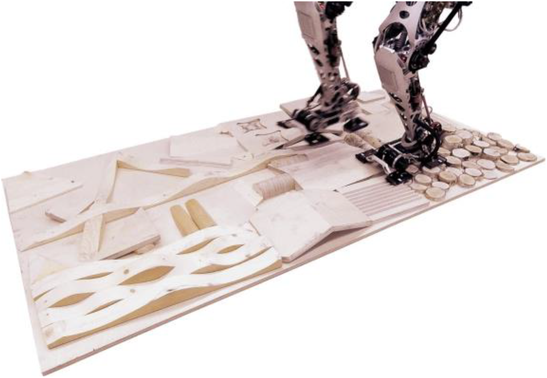
In the experimental test scenario, see Figure 6, L
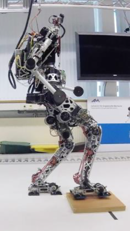
Experimental early-contact scenario with an undetected, 4-cm-high wooden board.

Sagittal torso inclination in an early-contact situation for the previous (ref) and proposed method (new). Positive values correspond to a forward inclination.

Right foot’s vertical contact forces in an early-contact situation for the previous (ref) and proposed method (new). For the time right after the impact no data is available as the FT sensor was overloaded.
Related work
An early-contact concept is especially important for robots with position-controlled joints with the resulting high, intrinsic stiffness. There are several ways to mitigate the impact effects of the swing foot on uneven terrain, such as the modification of the joint controller gains based on the gait cycle timing 24,25 or the activation of a ground reaction force controller once the swing foot is in contact. 10 Another strategy is the implementation of reflexive heuristics that change the vertical trajectory of the swing foot when an early contact occurs—that is, when the vertical contact forces exceed a certain threshold. 8,26 Other approaches trigger a replanning of the gait-cycle trajectories once an early contact occurs 23 or combine a fast walking-pattern regeneration with heuristics to stop the swing-foot upon early contact. 9 While these global approaches certainly have the ability to consider a reduced dynamics of the system in the updated trajectories, the latency from an early-contact event to an actual change in trajectories is usually about 20 ms—this may lead to high impact forces for fast walking on uneven ground. For the proposed method, we therefore restricted ourselves to maintaining the original trajectory plan and to modifying the swing-foot trajectory based on the combination of a reflexive heuristic with force control at a latency of only 1 ms. Furthermore, findings with our previous early-contact method 23 indicate that actually maintaining the original step timing is beneficial, as the effective double-support phase is then extended in the presence of such disturbances. The combination of force control and reflexes has already been described in related work. 17,25 In contrast to related work, our approach includes an additional modification of the planned load on the impacting foot. This avoids bouncing effects of the impacting foot just after the early-contact event and allows for higher impact velocities.
Unplanned partial footholds
Usually, full foot contact with the environment is assumed for force-control approaches on humanoid robots. In scenarios with partial contact between the robot’s feet and the ground, however, the actual contact dynamics can be quite different. In this section, we present a new approach to considering the actual contact geometry of the foot in the ground force-control scheme.
Control approach
As described in the previous sections, we use a hybrid position/force-control scheme with an explicit contact model to link the force-controlled position/orientation

The contact geometry (assuming a flat foot) is included in the matrix
To integrate the contact model into our force-control approach, we invert (13) and derive it with respect to time to get


Mathematically, (14) and (15) are identical descriptions. It is, however, difficult to measure the inertial state of the contact
By solving (6) for


which replaces (8). The first term of (16) is a feed-forward control part that compensates for the temporal change of the contact geometry. When the contact closes,
Contact geometry estimation
The foot contact geometry is measured based on the state of the discrete contact switches located in each foot pad of L

Contact estimation pipeline.
1. CoP calculator: Based on the full 6-axis data from the FT sensor, the location
2. Contact estimator: This module contains several strategies to improve the quality of the raw sensor contact state: A contact closing delay is applied to the sensor data upon first detection of a contact, that is, a contact state must be active for a certain duration Contacts may only close based on sensor data, but not open again. This assumption is necessary, as the discrete nature of the contact sensors otherwise leads to instabilities caused by permanent transition between closed and open contact states. Therefore, if a pad contact was closed in the past, it remains closed in the enhanced state. The enhanced state is reset to zero—that is, no contact—in the swing phase of the corresponding foot. The calculated position of the CoP is utilized to detect contact-closing transitions, which cannot—or not on time—be detected by the contact switches. At least one pad must have detected contact for this algorithm to be activated. The general principle is simple: Once the CoP is outside the geometric region of closed contact pads, some of the other pads must also be in contact. A more detailed description of our approach is visualized in Figure 10. The algorithm handles all permutations of the three scenario classes shown there. For classes (a) and (b), only one dimension of
3. Geometry calculation: Based on the known geometry and location of the contact pads, and the enhanced contact state from the Contact Estimator, the estimated contact geometry parameters for each foot are calculated. These consist of the position of the contact area centroid (

4. Assembly and filtering: The contact geometry parameters calculated in the previous step are now used to actually compute the raw contact model matrix

The filter is applied element-wise, that is, every matrix element is filtered independently. This step represents the end of the contact estimation process, and the resulting contact model is then used for the control approach described above.
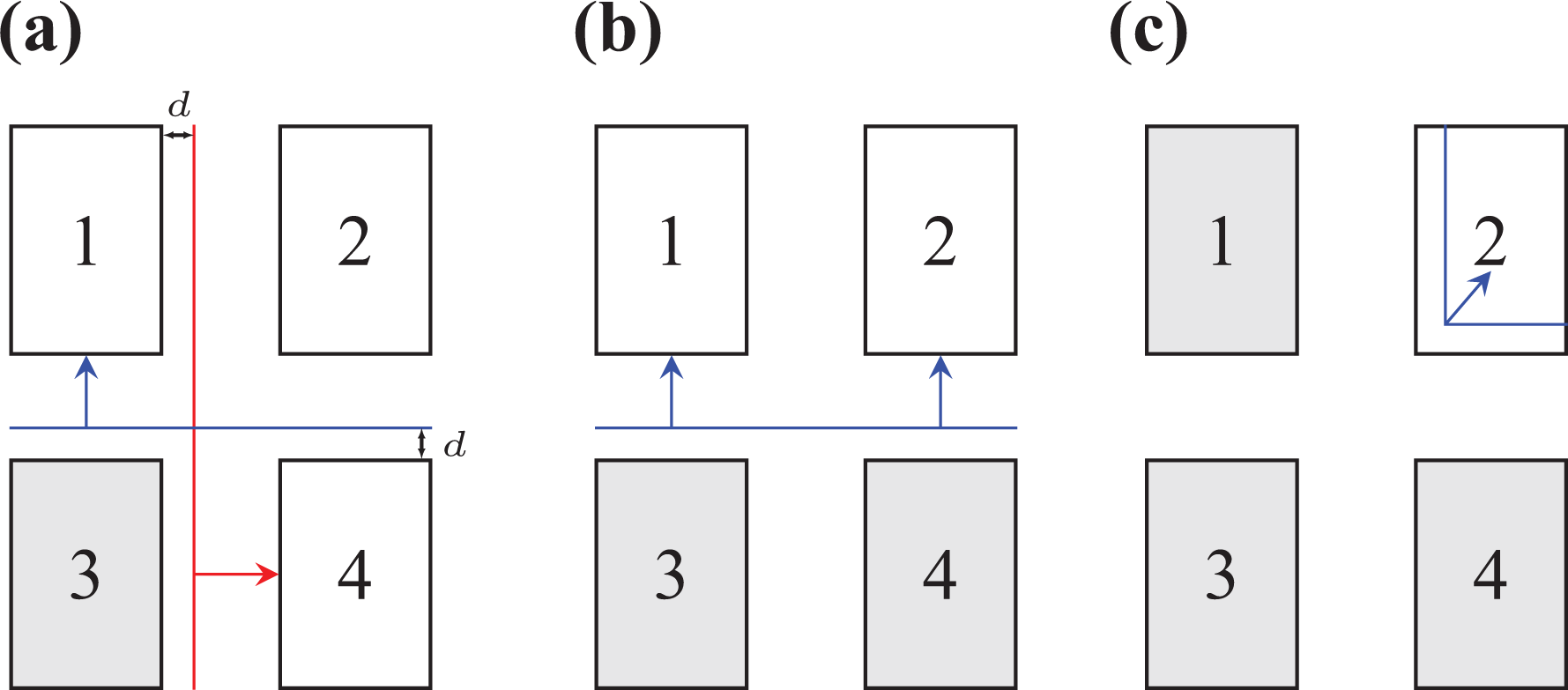
Top-down view of the foot with its four pads. Grey pads have already been detected as closed contacts in these three exemplary states. The boundaries (red, blue) for the CoP-based enhancement of the contact state are defined by the pad geometry and a margin d. If the location of the CoP crosses a boundary in the direction of the corresponding arrow, the pad(s) pointed to are enhanced to closed state. (a) 1 Pad, (b) 2 Pads, and (c) 3 Pads.
Implementation
In this section, we briefly describe restrictions and limitations we had to put on the original control law formulation (16) in order to apply the method to L
First, we had to assume
Second, the inverse contact model


This way, full-contact feedback is not limited in bandwidth, but partial-contact force feedback is.
Validation
The partial-contact method is evaluated in experiments with L
Experimental partial contact scenario with an undetected, 4-cm-high wooden board. The board is positioned to induce a heel-only contact of the right foot.

The raw and enhanced contact state for the right foot in the experiment with the dynamic contact model. The value is bit-encoded with 15 being all pad switches closed and 0 being no contact.
In Figure 13, the sagittal inclination angle of the robot is shown for the static (

Sagittal torso inclination for a heel-only, early-contact situation with the static (ref) and dynamic (new) contact model.

Controller output of the foot-tilt angle modification (y-axis) of the right foot with the static (ref) and dynamic (new) contact model.
Other unplanned partial foothold situations—for example, a toe-only contact—were also successfully tested with this method. The results are shown later as part of the validation of the combined methods.
Related work
To the authors’ knowledge, there has only been little research on the use of terrain information directly in the ground reaction force control. One interesting approach uses a foot with four point contacts with one force sensor in every corner 27 to get information on the contact geometry. The work uses a set of foot-motion primitives—entitled environmental modes—to control the contact forces that affect the zero moment point (ZMP). Furthermore, a strategy for a two-point contact along the diagonal axis of the feet is described to avoid instability in case the desired ZMP is on that axis. Other work proposes the use of two different force sensors at the center and front position of the foot. Based on the two force sensor readings, a heuristic detects if uneven terrain is present and lowers the stiffness of a virtual impedance of the ankle joint. 28 The parameters used for the virtual impedance are predefined and switch in a digital way when uneven terrain is detected. In contrast to our work, both approaches have no direct coupling between the contact geometry information and a force control’s contact model—that is, the sensitivity of the controllers is not adapted for different contact areas. Another approach estimates the rough terrain profile based on direct kinematics and the location of the center of pressure at initial touchdown. 16 The disturbed robot is driven back to the reference trajectories by using the updated kinematics and IMU data. Also, in other work, the actual center of pressure is used to determine basic information on the contact state and to heuristically adapt the motion of the robot. 29 The contact area, however, cannot be directly measured from the instantaneous CoP information. Still, it is possible to use an active exploration mechanism of the foot to determine the current contact area. This is used on the robot Atlas to walk on partial footholds and even line contacts. 30 While that contribution focuses on the generation of the CoM trajectories and balancing with such narrow support regions, our work focuses on how to realize already planned contact wrenches when there is an unplanned partial foothold.
Contact forces through CoM acceleration
The ground force-control schemes for humanoid robots usually—and implicitly—assume an inertially fixed torso. That is because the methods applied originate in the field of robot manipulators—where closed kinematic chains exist. Humanoid robots, however, have a floating-base dynamics, which can additionally be exploited for contact force generation. We have already shown the potential of our approach for the single-support phase. 12 In this article, we generalize the idea to all phases of the gait cycle and integrate it in this more general force-control scheme.
Control approach
The method is based on a simple floating-base dynamics model of the robot, which is directly integrated into the force-control scheme. When the conventional force-control scheme fails to track the desired forces/torques, a control error
The utilized model consists of a point mass of the robot’s total weight m at the robot’s CoM and is depicted in Figure 15. Note that all quantities are described in the torso-fixed frame of reference T and not in the inertial frame of reference. We can write the desired vertical acceleration of the CoM Illustration of the used dynamics model with the vertical acceleration of the CoM 

The activation factors
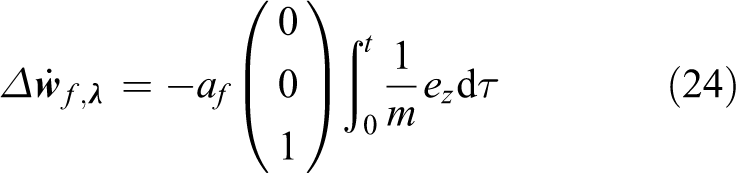
This modification of the vertical foot velocity is added to the force-control output
CoM height tracking
The method described with (24) can already effectively accelerate the CoM to generate missing contact forces. The approach is, however, local in time and not limited to certain walking phases. Therefore, the actual position of the CoM needs to be constrained—or kinematic limits are violated. Thus, we use a virtual spring and virtual damper between the actual vertical CoM position zc and the reference position

with the linear stiffness K and damping coefficient D. Consequently, the control law (24) changes to

and the CoM is now constrained by the dynamics of the resulting spring-mass-damper system. Furthermore, the gain factor
Implementation and validation
To apply the method on L
In the validation scenario, L

Sagittal torso inclination for walking on an undetected 4-cm or 6-cm-high board without (ref) and with CoM dynamics (new) in the force controller. At time
It does, however, have a clear advantage in (subsequent) late-contact situations. The dynamics model in the force controller enables L
Discussion
We would like to provide a few words on the theoretical stability of the proposed approach when the robot’s mass and the ground contact are considered a dynamic system. The double-integrator in the control approach (26) introduces a significant phase lag above the eigenfrequency of the system. This causes a small phase margin and may—depending on the model uncertainties like the contact stiffness and the joint controllers—lead to instability. The superposed direct force-control scheme (8), however, acts as a lead compensator, that is, the phase margin—and therefore stability—is increased by the combination of the two methods.
Another property of the approach is observed by adding (25) to the desired CoM accelerations (23). The model equation (23) then changes to

which corresponds to the equations for admittance control of the CoM directly. This controller operates on the tracking error ez—not on the actual forces—and is superposed on the direct force-control scheme described in (8). In the authors’ opinion, this combines the best of the two concepts: The robot’s feet in general behave stiffly when tracking desired force trajectories (direct force control). But for forces exceeding the desired set-point, the robot’s feet behave compliant as an admittance defined by K and D. Forces below the desired set-point trigger an acceleration of the CoM to reduce the error by means of dynamic movements.
The method indirectly modifies the vertical CoM trajectory. Recently, it was shown that a robot can be balanced solely by modifying the CoM height trajectory. 31 In our case, the trajectory modification is influenced by the terrain and model inaccuracies, therefore we currently cannot prove stabilizing effects caused by the induced height variation. However, there is also indication of beneficial behavior in case of tippling over the edges of the feet. For example, a forward inclination of the robot also leads to an acceleration of the CoM in the forward direction as we accelerate along the torso-fixed z-axis. Such behavior allows the ZMP to stay in the support-polygon and delays the forward inclination.
Related work
Admittance control—also known as position-based impedance control—is often utilized to mitigate the landing impacts of the swing foot. One approach for robots with position-controlled joints is to reduce the swing leg’s joint controller gains just before anticipated contact. 24,25 Alternatively, admittance control can be implemented by modifying the desired trajectories based on FT sensor information. 18,19,32 –34 The force reference for this controller usually depends on a predefined 18,32,34 or previously recorded force profile. 19 Later work extended the concept to using model-based force references—that is, the output of a ZMP controller. 10 In general, admittance control leads to a trade-off between impact mitigation during the landing phase and the control of the desired forces once the foot is in safe contact with the ground. In the first case, the stiffness should be relatively low, while for the second case the stiffness needs to be high in order to track the desired force profiles. In related work, this is often resolved by varying the impedance parameters based on the gait cycle phase. 18,19,33,34
A different approach for force control on biped robots with position-controlled joints is the direct force-control scheme, 7,12,21 which does not impose a certain impedance/admittance on the system but tracks a given force directly. The approach presented here consists of a superposition of an admittance controller and a direct force-control scheme. This resolves the trade-off of the usual admittance control, as desired trajectories can be tracked with high effective stiffness (direct force control), while disturbances in the vertical direction are mitigated by the admittance controller.
At robots with torque-controlled joints, all bodies (and the CoM) are intrinsically accelerated by the local joint control. The problem changes from a force-control to a position-control task of the CoM. Popular control frameworks usually deploy high-gain PD control to track a CoM reference trajectory. 11,14 Only recently, interesting work replaced the hard constraint on the height of the CoM with a soft constraint of the knee joint angle. 35 Depending on the parametrization, this method should allow for similar behavior to the work presented here. Other relevant work tracks the CoM via a 3-D Cartesian impedance law (or low-gain PD-control). 13,15 While this yields interesting compliance for stationary balance experiments, to the authors’ knowledge, the approaches were not extended to disturbance rejection during walking.
Combination of the methods
The three proposed methods can cooperate as a combined strategy for ground reaction force control on humanoid robots. Integration of the methods is done by superposition of the controller outputs (11), (21), and (26).
While the early-contact method has already been tested in combination with the other methods, the combined strategy is experimentally validated separately. The considered scenario is similar to the partial contact scenario shown in Figure 11, however, the position of the board is changed to induce a toe-only initial contact. Compared to the heel-only early-contact, this means even greater disturbance on the system, as the tracking error of the ZMP—ideally it should remain in the stand-foot—increases. Figure 17 shows the sagittal inclination of the robot for the method with changing contact geometries only and for the integration of all methods into a combined force-control scheme. The results show a significant reduction in the maximum sagittal inclination angle (

Sagittal torso inclination for a toe-only, early-contact situation. In the reference (ref), only changing contact geometries are considered; the combination additionally considers the CoM dynamics in the force controller.
Furthermore, with the proposed force-control scheme, L
Conclusion
In our contribution, we presented a ground force-control scheme for biped robots that allows for the terrain-blind and fast traversal of uneven ground—including unplanned partial footholds. This enables the biped robot L
The results show that the consideration of the actual contact geometry in the force-control law has significant stability advantages for unplanned partial contact with the ground. Furthermore, the insertion of vertical CoM dynamics into the force controller enables L
Current limitations are imposed by the contact sensors at the feet, which can detect partial contacts only with a quite narrow spatial resolution (pad in contact or not). In addition, the reliability of the contact sensors (false contacts) degrades over their lifetime. Above all, the suboptimal design of the IMU mount greatly limits the performance of our approaches; it needs to be reworked. For future work, we plan to integrate tactile sensing elements on the feet to get a better estimation of the actual contact geometry. 36
Footnotes
Acknowledgments
The authors thank Georg König for building the uneven terrain testbed and Philipp Seiwald, Nora-Sophie Staufenberg, and Moritz Sattler for their help carrying out the experiments with L
Declaration of conflicting interests
The author(s) declared no potential conflicts of interest with respect to the research, authorship, and/or publication of this article.
Funding
The author(s) disclosed receipt of the following financial support for the research, authorship, and/or publication of this article: This work was supported by the German Research Foundation (DFG) and the Technical University of Munich within the funding programme Open Access Publishing. It was furthermore supported by the German Research Foundation (DFG) in the context of grant number 407378162.
Appendix 1
The raw inverse contact model matrix is given by
with
The used discrete-time low-pass filter function