
Abstract
This article presents an experimental characterization of ExoFinger, a finger exoskeleton for finger motion assistance. The exoskeletal device is analyzed in experimental lab activities that have been conducted with different users to characterize the operation performance and to demonstrate the adaptability of the proposed device. The behavior of this device is characterized in detail using sensors to measure finger motion and power consumption. Sensor measures also demonstrate the given motion assistance performance in terms of an electrical finger response and finger temperature by resulting in an efficient solution with a large motion range of a finger in assistance of recovering finger motion.
Introduction
Exoskeleton devices are developed with great interest to assist human motion, and many of them are focused on rehabilitation procedures. 1 However, exoskeleton development can be focused on solving the challenges of the following four main applications: rehabilitation, exercising, motion assistance, and extension of human capabilities. In particular, finger exoskeleton devices are challenging because of the required range of motion and the small moving parts involved. An important number of developments have been carried out to address several aspects of finger motion assistance as reported in ref. 2 as a review of soft robotic hand exoskeletons and in ref. 3 as guidelines and best practices for general exoskeletons.
Among common problems with finger exoskeletons, it is possible to outline that they usually are not adaptable for different subject fingers since they are designed specifically for each patient as pointed out, for example, in ref. 4 ; they have a large structure such as in the examples in refs 5,6 ; they are heavy such as in the examples in refs, 7,8 or they are not easily wearable such as some configurations presented in refs. 9,10 However, the need for new exoskeleton configurations, when combined with the development of new materials, manufacturing procedures, sensing improvements, and control advances, suggests practical approaches to address the abovementioned problems. A solution considering recent available technology is proposed by Kim et al., 11 who developed a biomimetic finger extension mechanism to mimic the origin, structure, and orientation of an extensor tendon. Popov et al. 12 presented a compact light exoskeleton using a soft structure for hand assistance in daily activities. Wang et al. 13 proposed a configuration that combines pneumatic actuators and magnetorheological materials to implement different functional modes. Li et al. 14 presented a compliant finger exoskeleton using superelastic transmissions based on the development of new materials.
Other topics, such as a kinematic synthesis of new configurations, are still a field of research interest. Tan et al. 15 presented different kinematics configurations for finger exoskeletons. Luzi et al. 16 explained the synthesis of mechanisms that approximate human finger motion instead of trying to replicate the exact movement of only one person. The integration of different aspects produces new approaches like, for example, in refs 17 –19 by combining variations of kinematics with elastic actuators, or in ref. 20 by applying control algorithms within finger exoskeleton development.
The lack of a suitable exoskeleton for finger motion assistance is still an area of opportunity for developing new configurations since the design of a hand exoskeleton faces a wide range of challenges, as also stressed in ref. 14 The needs and expectations must be fulfilled with different criteria such as safety, a good range of motion, ergonomic usability, transportability and wearability, and a proper autonomy time, as also pointed out in ref. 13
A specific research line is addressed on integrating new concepts in the development of exoskeletons for motion assistance as reported in ref. 21 referring to considerations of comparable hand velocity and torque when doing everyday tasks. Moreover, 22 several groups work on fundamental grasping mechanics based on the design and validation of anthropomorphic robotic hands. The above aspects’ application gave a conception of the ExoFinger design whose developments and results are reported in refs. 23,24
The article’s main contribution is to report an experimental characterization of proper operation of the proposed ExoFinger finger exoskeleton with a variety of sensors for motion control and medical monitoring. In addition, the proposed finger exoskeleton mechanism has a peculiar structure with two degrees-of-freedom (DOF)’s for a full finger motion range while monitoring the motion assistance. The combination of the implemented sensors in the reported position at the finger is not invasive. This approach significantly contributes to the importance of combining data from different sensors to prevent invasive medical systems. The reported approach and validation results can be of interest both for further development in research (design and analysis) and for applications of solutions with useful features such as user-oriented and medical benefits.
ExoFinger, a finger exoskeleton
The ExoFinger exoskeleton is designed and prototyped at the Laboratory of Robot Mechatronics in Rome. The parameters and the configuration of the proposed eight-bar linkage mechanism for assisting human finger motion are part of an Italian patent too. 24 A description of the design procedure, including finger motion study, synthesis of the mechanism, and finite element analysis, is presented in ref. 23 Preliminary numerical and experimental validation of ExoFinger is presented in ref. 25 to demonstrate the exoskeleton performance from theoretical to practical viewpoints. The presented exoskeleton is designed with two interconnected four-bar mechanisms as a linkage of two DOF. Therefore, it is capable of providing independent motion to the metacarpus phalange and distal phalange.
Figure 1 shows a conceptual scheme of the ExoFinger exoskeleton with main ideas. Figure 1(a) shows the three joints of a human finger considered when designing ExoFinger, where the metacarpus joint is labeled as MCP, the proximal phalange is labeled as PIP, and the distal phalange joint is labeled as DIP. The joint angular displacements are indicated as θM, θP, and θD, respectively. The exoskeleton is driven by two actuators that correspond to the servomotors used to drive each DOF. The exoskeleton is equipped with four different types of sensors to acquire information during an assistance procedure. One type of sensor measures angle displacements, angular velocities, and linear acceleration on the metacarpus and distal phalanges, which are measured with respect to the XY reference frame in Figure 1(a). The other three sensors are considered to measure electrical activity on the finger, temperature change during exercising, and motor’s power consumption, Figure 1(b).

A conceptual scheme of ExoFinger exoskeleton: (a) parameters of human finger and (b) a block diagram.
ExoFinger is designed with portability/wearability and adaptability features that can be useful for a wide range of users. The design and implementation consider possible attachment regions where the attachment points can fix the exoskeleton to a finger in different subjects. Figure 2(a) shows the kinematic configuration of ExoFinger combined with a general position for installation on a finger of a human hand. ExoFinger uses five attachment regions to be fixed on the human hand, where two of them are on the palm and back of the hand (A1 and A2), two on the metacarpus phalange (A3 and A4), and the last one on the distal phalange (A5). These five regions are adaptable to different subjects and can provide different attachment points for different anthropomorphic sizes. Therefore, finger positions’ behavior could differ from one to another since the distance between the MCP, DIP, and PIP joints can be different. There also can be some variation associated with the position of the fixing points with different subjects. However, angular displacement in the finger joints will behave similarly in different users. Figure 2(b) shows the ExoFinger prototype with the attachment points when it is installed on a subject. These regions ensure the attachment of ExoFinger during a motion assistance procedure while keeping the mobility of the assisted finger. This configuration also provides comfort to the patient since it is not rigid and can be adapted to the human hand morphology.

ExoFinger prototype on a human hand: (a) a kinematic scheme and (b) installed on a subject.
The input angle for the first-driven linkage in Figure 2(a) is labeled as δ, and the angle for the second mechanism is indicated as β. The position and size of actuators also were selected to ensure portability and comfort to a user.
Testing layout
A three-dimensional (3D) printed prototype solution is implemented for laboratory testing with the four mentioned sensors, motors, and Arduino boards as in Figure 1(b). Figure 3(a) shows the implemented architecture of electronic hardware with market components. Figure 3(b) shows the location of sensors and actuators when ExoFinger is attached to a human finger with electrodes (1), for the electromyography (EMG) sensor (2), thermistor on the metacarpus phalanx (3), inertial measurement unit (IMU) (6) on the metacarpus phalanx, and the second IMU (6) attached to the distal phalanx, one servo motor (7) to drive the first four-bar mechanism, and the other servo motor (8) to drive the second DOF. The first mechanism requires a larger torque, and for this reason, the servomotor has more torque capabilities. The ExoFinger prototype is equipped with servomotors model MG995 R and MG90 S by AZDelivery Inc. whose weight is 55 g and 14 g, and maximum torque is 1.1 Nm and 0.3 Nm, respectively. The ExoFinger design is powered by two motors for the peculiar functionality to have the possibility to move the phalanxes independently, whereas a synchronization of the two motors permits also a coordinated motion of the full finger. Consequently, the two four-bar linkages are used to transmit the motion of each motor to the corresponding phalanx. A prototype has been assembled by using the above commercial components for servo motors and sensors while the link bodies were manufactured by a 3D printer using polylactic acid material to have a lab prototype with low-cost features and easy link reconstruction/change.

Design of experimental setup of ExoFinger prototype: (a) a scheme and (b) a laboratory setup.
To overcome issues with prototypes of multiple analog readings and to assure proper measurements, the analog inputs’ acquisition process was split into different circuits. The system consists of three microcontroller boards that are interconnected to keep an appropriate sampling timing. There are two Arduino Nano boards to measure electrical finger activity and temperature, respectively. Current sensors are read within the mainboard, and all data coming from the first two boards are collected and sent together to a personal computer for acquisition purposes.
A bioelectrical activity EMG sensor is attached to a finger to identify the electric finger response associated with a given motion. Sensor readings are filtered and numerically integrated using hardware to obtain apparent electrical activity from a finger. The reference electrode is set up near the wrist with the main electrodes attached to the metacarpus and distal phalanges, respectively, using conductive fabric electrodes. The snap cable connectors are attached using snap buttons. This setup avoids the use of disposable electrodes and ensures good skin contact to measure electrical activity from the assisted finger. In addition, a temperature sensor is attached to the metacarpus phalange to identify the temperature change during the finger motion. This sensor is a thermistor that was previously characterized to obtain the parameters of a nonlinear thermistor model. The sensors EMG and thermistor are used to detect a physiological response of the assisted finger motion.
Two analog current sensors are implemented to measure the electrical current that is used by the actuators. With this information, the ExoFinger software estimates the power consumption of each motor independently. One IMU sensor is installed on the metacarpus, and another is attached to the distal phalange to identify the angle displacements, velocities, and acceleration of the finger joints. This kind of sensor measures motion in terms of linear acceleration and angular speeds to estimate each phalange’s angular position.
Performance characterization
Figure 4 shows snapshots of a test with a finger moving from full-extended configuration up to a closed position. Several tests were carried out, checking the operation, and performance of ExoFinger exoskeleton in different users with different sizes of the used index finger. The experimental characterization was experienced with three different subjects. Informed consent was obtained from all the participants in accordance with the ethical standards. Test duration is up to 1 min with a repetition of opening–closing of the finger of 3 s cycle with a sampling rate of 100 Hz. Figures 5 to 10 show illustrative examples of obtained results in those tests like in Figure 4.
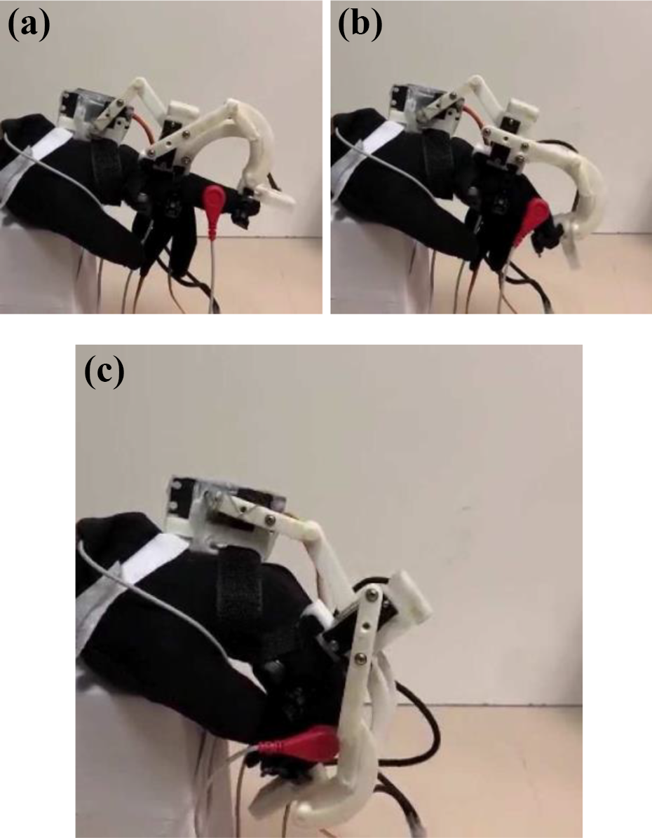
(a) to (c) A snapshot of the exoskeleton motion during a test with sensors.

Results of measured motion in terms of joint angles of (a) MCP and (b) DIP. MCP: metacarpus joint; DIP: distal phalange joint.

Results of measured motion in terms of angular velocity of (a) MCP and (b) DIP. MCP: metacarpus joint; DIP: distal phalange joint.

Results of measured motion in terms of MCP linear acceleration along: (a) x-axis and (b) y-axis. MCP: metacarpus joint.

Results of measured motion in terms of DIP linear acceleration along: (a) x-axis and (b) y-axis. DIP: distal phalange joint.

Test results in terms of power consumption in (a) MCP joint motor and (b) DIP joint motor. MCP: metacarpus joint; DIP: distal phalange joint.
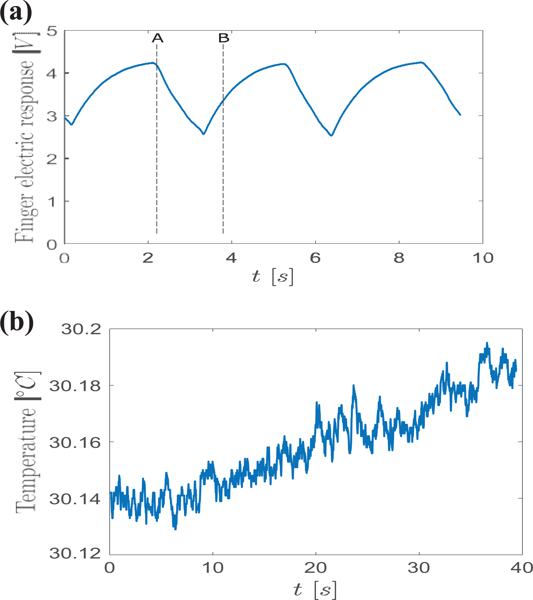
Test results in terms of (a) finger electrical response and (b) temperature.
The laboratory prototype was tested experimentally while driving the motion of a finger. The information was collected with the four types of sensors, and it is used to characterize ExoFinger behavior when assisting a finger motion. Figures 5(a) and 6(a) show the angular behavior in displacement and velocity of the metacarpus MCP joint for a complete motion test, and Figures 5(b) and 6(b) show the angle and velocity of the distal DIP joint during the test. Maximum values in Figure 5 correspond to a complete flexion and minimum values to an entire extension position of the assisted finger. These values are labeled in Figures 5 and 6 as A for complete flexion and B for complete extension. All other figures show the same labels to compare and correlate information from one figure to another for finger extension in Figure 4(a) and finger flexion in Figure 4(c).
Angular displacement for metacarpus and distal phalanges can be driven independently thanks to the two driving motors. However, in combination, they produce a complete flexion or extension for the finger that can be reproduced uniformly and repetitively by ExoFinger. In the carried out experiments, the second DOF, which drives distal phalange, is driven by the first angular displacement for synchronization purposes. ExoFinger software maps the second motor’s motion as a function of the first one using a linear relation as

where the parameters of the linear equation are characterized considering the mechanical setup of ExoFinger and a range of motion for the subject’s finger. The actual relation of the metacarpus and distal phalange does not conserve the linear relation between driven inputs, but the kinematics of Exofinger governs Eq. (1) expresses a linear relation between the two input angles on the servomotor axes and the coefficients are used to characterize the linear correspondence between the two input motions as to give the second motor depending of the first one in ensuring synchronization and coordination of the phalanges with a human-like motion. Figure 5 also shows the positive correlation between both phalanges, the synchronization to reach flexion and extension position simultaneously, and the nonlinear relation between the measured phalanges.
The measured angular velocity behavior in the time domain for θM and θD is reported in Figure 6 and corresponds correctly to the estimated angular displacement in Figure 5. Figure 6(a) and (b) shows that velocity is close to zero when the finger is in full extension position and full flexion position corresponding to the change direction from one position to another. However, it is not zero due to small deviations when estimating angular position. Angular velocity behavior shows that motion from one extension to flexion position is not symmetric since they present different profiles. This characteristic is evident in the motion of metacarpus phalange in Figure 6(a) where absolute angular velocity value gets a value of around 40, but when moving from extension to flexion position, the absolute value of velocity is larger. The change from extension to flexion occurs with a larger speed because finger tissue contributes to that motion. On the contrary, the finger tissue presents a mechanical resistance to reach a full extension position and this characteristic acts as a natural damper that smooths change from configuration A to B in Figure 6(a).
The angular velocity behavior of distal phalange in Figure 6(b) shows that its motion is more symmetric than metacarpus phalange when comparing the absolute value of the maximum and minimum of the plots. However, angular velocity presents a significant change when it is close to a full flexion position as A in Figure 6. This change in velocity occurs because the finger moves slower due to the hand resistance to a full flexion position.
The distal phalange translation from one position to another is larger than in the metacarpus phalange, and displacements in the xy reference plane are larger. Those displacements can vary from one user to another since the size of finger phalanges can be different. However, linear acceleration can describe similar behavior even with different subjects. The linear acceleration in Figures 7 and 8 is measured with respect to the reference frame in Figures 1 and 2, with the possibility to compare each other in the extension and flexion configurations of an assisted finger by looking at the labels A and B. The motion of each phalange runs in the xy plane and therefore motion in the z-axis is neglected. The linear acceleration of metacarpus in Figure 7(a) shows that motion takes place with a larger value in the x-axis. The acceleration in the x-axis shows a greater correlation with angular displacement of the finger, while linear acceleration in y-axis shows a different profile. Linear acceleration of the distal phalange in Figure 7(b) shows larger maximum and minimum values because the displacement of this phalange is larger, and those values occur when the motion changes from one position to another. This phalange experiments larger acceleration in the y-axis, which is the opposite of the metacarpus phalange behavior with larger acceleration values in the x-axis.
Figure 9(a) presents a measure of power consumption by measuring the electrical current of MCP driving motor with a current sensor. This motor requires more energy than the other motor to move, and for this reason, a larger motor was implemented. Figure 9(b) shows the power consumption behavior of the motor to drive PIP and DIP joints. It uses a smaller motor since the stiffness for those joints is smaller. These plots show that the required energy when moving a finger from extension to flexion is considerably smaller than the motion from flexion to extension. To support this observation, labels can be used to compare data from the angular position of the metacarpus phalange in the reported results.
Figure 10(a) shows the electrical response that is measured from electrodes attached to the index finger. The obtained behavior corresponds to the ExoFinger driven motion, indicating that the finger responds to the assisted movement, also with physiological motion actions. Fabric-based electrodes ensure a good sensitivity along the metacarpus and proximal finger phalanges so that it is possible to detect electrical finger activity even in motion conditions. The commercial electrodes designed for other applications were adapted for ensuring successful connectivity for the finger phalanges. It can be observed that electrical activity drops when the finger starts moving from the flexion to the extended position, which indicates that electrical activity is correlated with a given assisted motion. This behavior can also be in correspondence with electrical contraction or extension of a muscle that can also be observed by measuring electrical activity on the assisted finger. Figure 10(b) shows the measurement of a temperature sensor with an increasing temperature after 40 s of finger motion using ExoFinger. The sensor was installed and left in contact with the finger to ensure a proper initial condition. Once the movement has started, an increasing activity can be observed in this figure as a positive effect of the motion assistance in stimulating local blood circulation with tissues heating.
Table 1 lists the maximum and minimum values of each measured variable as a summary of the acquired data in Figures 5 to 10. The total angular displacement is ΔθM = 28.25 deg and ΔθD = 79.18 deg, respectively, for each phalange, which represents enough range of motion for exercising and rehabilitating procedures. ExoFinger can be adjusted to give a smaller range of motion if a user requires it. Angular velocities can provide adequate speed for the exercising assistance, but they can be configured to a slower behavior for rehabilitating motion assistance. The values of acceleration show a smooth motion that can assist a subject without causing injuries for sudden changes of movement. Power consumption has a proper value to implement ExoFinger using batteries and give assistance during several sessions. The total power consumption labeled as WT is the energy used by the motors for one cycle of 3 s. Finally, the change in temperature is not significant, but rising temperature occurs just after the motion assistance this information can be used to monitor the finger motion effects.

EMG: electromyography.
Conclusions
This article presents an experimental characterization of an assisted motion of a finger when using the ExoFinger exoskeleton. A set of actuators, sensors, and the ExoFinger linkage can drive, monitor, and guide a proper assisting motion, respectively. The designed exoskeletal system is compact, lightweight, and inexpensive, with suitable characteristics in assisting a finger motion for exercise or rehabilitation. ExoFinger exoskeleton has been tested successfully, with a prototype showing a smooth behavior when following a natural finger motion. The mechanism design has also permitted the use of suitable sensors to control and monitor the finger motion and its efficient result.
Footnotes
Acknowledgements
The first author acknowledges Consejo Nacional de Ciencia y Tecnologıa and Instituto Politecnico Nacional for supporting his period at Rome Tor Vergata University in the Annual Year 2019–2020 within a double Ph.D. degree program.
Declaration of conflicting interests
The author(s) declared no potential conflicts of interest with respect to the research, authorship, and/or publication of this article.
Funding
The author(s) received no financial support for the research, authorship, and/or publication of this article.