
Abstract
In this work, the design, manufacturing, instrumentation, and application of a two-finger exoskeleton with force feedback are presented. The exoskeleton is based on remote center of motion mechanisms in order to avoid mechanical interference with the user’s fingers and is manufactured by three-dimensional printing. The developed exoskeleton is applied in a mobile robot teleoperation by mapping the finger movements in forward and turning commands for the robot. The presence of obstacles detected by the robot is sensed by the user by means of a feedback force. The problem of simultaneously communicating a data acquisition card and the robot hardware by MATLAB ® Simulink® was solved by using an external Wi-Fi module. The result is a lightweight exoskeleton which is able to communicate bidirectionally with a mobile robot by a personal computer for teleoperation tasks. The success of the system implementation is proven by a set of experiments presented in the final part of the article.
Introduction
Over the last few years, the development of exoskeletons has become a very important area within robotics research. An exoskeleton is an anthropomorphic external mechanical structure whose kinematic chain maps onto the human limb anatomy so that there is a one-to-one correspondence between human anatomical joints and the exoskeleton’s joints or sets of joints.
1
These devices allow for the transfer of mechanical energy from the exoskeleton structure to the human body, and they are biomechatronic systems, because they integrate mechanical, electronic, and software engineering as well as biology (the user).
2
In particular, hand and finger exoskeletons have found use in applications in various areas in recent times, such as rehabilitation devices,
2
–9
virtual reality,
10
–12
and robot teleoperation.
13
–17
In this last context, a telerobotic system consists of different parts: a human operator, a haptic interface or master device, a slave device, a communication channel, and an interaction environment.
Furthermore, haptic interfaces are devices that enable interaction with virtual or physically remote environments. A haptic interface receives motor commands from the user and generates mechanical signals that stimulate human kinesthetic and touch channels. In general, haptic interfaces are typically designed for interaction with the hand, and are devices that (1) measure position or contact force and (2) display contact force or position to the user. 12,21,22 Therefore, haptic interfaces represent an ideal solution for the bidirectional information flow between the operator and the robot in a telerobotic system. When a hand exoskeleton is provided with a feedback mechanism, it becomes a haptic device which is able to generate commands for the robot movements by sensing hand and finger motion as well as providing feedback forces to the user in function of the remote environment data sensed by the robot. This type of mechanism improves the user telepresence by allowing the user to “feel” virtual objects more naturally. 22,23
Different kinds of mechanisms have been used in haptic hand and finger exoskeletons for telerobotic systems. Chen et al. 13 designed a hand exoskeleton based on four bar mechanisms obtaining a 15-degree-of-freedom (DOF) adaptive dorsal metacarpal (MC) base, which can be tightly attached to the back of patients’ palm as a slave system for rehabilitation purposes. The mechanisms are driven by shape memory alloy (SMA) actuators and the main problem in their design is that the motion frequency is quite low, which is the main limitation of SMA actuators. Cortese et al. 14 propose a hand exoskeleton as a part of a master–slave telerehabilitation system. The hand exoskeleton is used as the slave unit and consists of a powered hand orthosis, a mechatronic system made up of three main subsystems: the wearable exoskeletal orthosis for the active assistance of the index and thumb fingers, the remote actuation block attached to the orthosis by means of a cable-sheath system, and the controller unit. The wearable exoskeletal orthosis is based on self-alignment mechanisms which provide force/motions to the carpal, MC, and phalangeal joints. 24 The adopted actuation strategy for this device is to remotely place the actuation system, use flexible transmission means in order to decrease the inertia of the moving parts, as well as enhance portability and wearability of the overall system. This device also employs a cable-driven actuation system through flexible sheaths, namely Bowden cables. The weight of the exoskeletal orthosis and the actuation subsystem is 778 and 494 g, respectively. The proposed actuator has a compact and portable design, but its main drawbacks are nonbackdrivability, limited stroke, and low power. Zhou and Ben-Tzvi 17 developed a haptic glove for two fingers to teleoperate a mobile robot. The mechanical design of each haptic glove finger consists of three main parts: three-link exoskeleton, an actuator unit, and two actuation cables. The actuator unit consists of a brushed DC-motor geared to a pulley through nonbackdrivable worm gears. A two-cable pull transmission is used to exert force in both directions for extension and flexion of the fingers. Each finger exoskeleton is modeled as a six-bar mechanism. In order to avoid mechanical interference between the mechanism and the user’s finger, the exoskeleton links must be a few centimeters above the finger which increases the size of the device. More recently, the same authors reported a new version for five fingers of the same haptic glove. 23 The main contribution of this work is the optimization of the mechanism’s geometry based on geometric and force transmission characteristics. However, the gap between the exoskeleton links and the user’s fingers remains a problem affecting the size of the device.
According to the revised literature, the main challenges associated with haptic hand and finger exoskeleton design are size and weight, easy fitting of the device on the human hand and be as light as possible; kinematic compatibility, meaning the exoskeleton should match the hand’s dexterity without limiting its range of motion and without mechanical interference with the user’s fingers; and dynamic range of force feedback, meaning the mechanism should be sufficiently versatile to be used in both highly sensitive and large force tasks. 17,23,24 In order to overcome these problems, remote center of motion (RCM) mechanisms have been proposed for the mechanical subsystems of haptic hand exoskeletons. 25 –28 RCM is mechanisms that are able to implement the rotation of a body around a fixed axis that is remotely located from the structure of the joint. 25,26 This is a necessary feature because the phalanges of the operator’s finger rotate around a point located inside their respective joints. To mimic the motion of the operator’s finger, the rotation centers of the exoskeleton mechanism should coincide with the rotation centers of the operator’s fingers to avoid the mechanical interference between the operator’s finger and exoskeleton mechanism. 27,28 Fontana et al. 25,26 developed a hand exoskeleton based on six-bar RCM mechanisms for virtual reality operations. They employed three motors for each exoskeleton finger and transmissions with cables and pulleys to produce a three-DOF mechanism. The main drawbacks for this exoskeleton are its size and the weight (1.1 kg). Fang et al. 27,28 designed a finger exoskeleton with force feedback as a master device to teleoperate a DLR-HIT Hand. The mechanical subsystem is based on four-bar RCM mechanisms and it is lightweight and compact.
In this work, the design, analysis, manufacturing, instrumentation, and application of a two-finger exoskeleton with force feedback are presented. The exoskeleton is developed for the index and middle fingers based on RCM mechanisms to avoid the mechanical interference with the user’s fingers and it is manufactured by three-dimensional (3-D) impression. The obtained device is a more lightweight and compact device than the exoskeletons mentioned above. Moreover, the two-finger exoskeleton fits easily on to the human hand while being kinematically compatible, and it does not limit the hand’s range of motion, nor is there any mechanical interference between the exoskeleton and the user’s fingers. The developed exoskeleton is applied in a mobile robot teleoperation mapping the combined finger movements in forward and turning commands for the robot. The presence of obstacles detected by the robot is sensed by the user in the form of a feedback force in order to provide information about the robot’s environment to the user. As previously mentioned, one of the main problems with teleoperated robots is the communication between the different parts of the system. With this in mind, the main contribution of the proposed system is to communicate simultaneously a data acquisition card and the robot hardware by MATLAB® Simulink® in order to establish a bidirectional communication channel between the slave device (mobile robot), the user, and the master device (two-finger exoskeleton). This problem was solved by using an external Wi-Fi module and creating a virtual serial port in the Simulink program. A comprehensive description of the hardware and software used in this implementation is provided in the manuscript. The result is a lightweight hand exoskeleton which is able to communicate with the mobile robot by a personal computer with a data acquisition card and a Wi-Fi module. This system is easy to implement by using accessible robotics kit and without the need for expensive commercial haptic devices. The system implementation is proved by a set of experiments presented in the final part of the article.
Exoskeleton design and manufacture
Technical considerations
As previously mentioned, exoskeletons are biomechatronic systems whose kinematic chain maps onto the human limb anatomy so that there is a one-to-one correspondence between human anatomical joints and the exoskeleton’s joints or sets of joints. Therefore, the exoskeleton mechanical design must be based on hand biomechanics and anthropometry. According to Leijnse et al., 29 index and middle fingers have a similar anatomical structure. From the wrist to the fingertip, these fingers are made up of four bones: MC, proximal phalanx (PP), middle phalanx (MP), and distal phalanx (DP). These bones are connected by the metacarpophalangeal joint, the proximal interphalangeal joint, and the distal interphalangeal joint (see Figure 1).

Bones and joints of the index finger (adapted from Leijnse et al. 29 ).
The anthropometric data of the average length for each phalangeal segment and the motion range of the index and middle finger joints were taken from the study by Ben-Tzvi and Zhou 3 and references within, as shown in Tables 1 and 2. In Table 2, FE denotes the flexion/extension movement and AA denotes the abduction/adduction movement.
Phalanx length (in millimeter). 3

PP: proximal phalanx; MP: middle phalanx; DP: distal phalanx.
Finger joint angular motion range. 3

MCP: metacarpophalangeal; FE: flexion/extension movement; PIP: proximal interphalangeal; AA: abduction/adduction movement; DIP: distal interphalangeal.
Mechanical fingers
The mechanism joints were modeled as RCM, meaning that the exoskeleton is able to track the finger movement without mechanical interference. The RCM allows the main links to have movement equidistant to the user finger phalanx, in contrast to modeling the mechanism joint as a simple revolute. 27,28
The mechanical fingers were designed based on the data presented in Tables 1 and 2. The proposed RCM is based on two coupled parallel mechanisms and their main characteristic is that the length of the opposite links is the same, as can be seen in Figure 2.

Remote center mechanism for the mechanical finger.
In order to obtain the links’ length of the mechanism for the index finger, the following considerations were taken into account: The distance (D) between the base of the mechanical phalanx and the user’s finger phalanx is 15 mm to avoid mechanical interference. Separation (S) between the mechanical phalanxes when the exoskeleton is fully extended is 2 mm. The mechanical phalanxes height (T) is 23 mm. The vertical distance (V) between the joints and the mechanical phalanx border is 6 mm. The horizontal distance (H) between the inferior joints and the mechanical phalanx border is 6 mm. The links of each interphalangeal joint are of the same length.
With these constrains and the geometrical relations, as shown in Figure 3, a sketch for the mechanical index finger was drawn and fully defined obtaining the dimensions for the parallel mechanisms.

Mechanism sketch for the mechanical index finger (dimensions in millimeter).
The procedure for designing the mechanical middle finger was similar and under the same considerations with the following exceptions:
The vertical distance (V) between the joints and the mechanical phalanx border is 7 mm.
The horizontal distance (H) between the inferior joints and the mechanical phalanx border is 8 mm.
With the obtained dimensions and considering the mechanical finger width of 22 mm, the three dimensional models for the exoskeleton phalanxes were developed with a wall thickness of 3 mm. The PP and MP were designed with similar geometries, while the DP was designed to give support to the fingertip. In Figure 4(a), a frontal view of the proximal mechanical phalanx is shown and its respective lateral view is presented in Figure 4(b). An isometric view of the distal mechanical phalanx is presented in Figure 4(c).
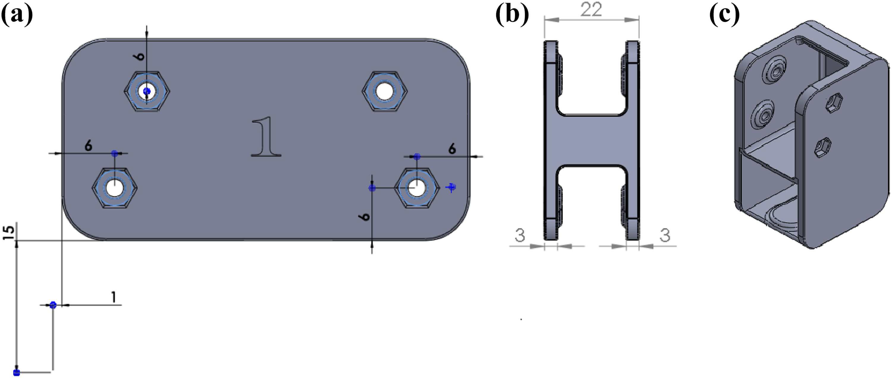
3-D models of mechanical phalanxes. 3-D: three-dimensional.
Manufacture and assembly
The components for the 3-D models of the mechanical phalanxes were obtained by 3-D printing using acrylonitrile butadiene styrene (ABS), while synchronous belts and toothed pulleys integrated into the mechanism links were used for the motion transmission between the mechanism’s joints (see Figure 5(a)). Because the motion between the long links of a phalanx is opposite, the synchronous belts were installed in a crossed configuration, as can be seen in Figure 5(b). The different angular motion ranges for each phalanx finger are achieved by the pitch diameter ratio of the pulleys. For the mechanical finger assembly,

Proximal mechanical phalanx.
In Figure 6(a), the assembly of the mechanical index finger is shown, and in Figure 6(b), the complete exoskeleton assembly is presented.

Exoskeleton assembly.
Dynamic analysis
A Ft = 5 N feedback force on the user’s fingertip is considered to select appropriate exoskeleton actuators, which according to the study by Rausch et al. 30 is sufficient for kinesthetic applications. The calculations were carried out based on the free body diagram of Figure 7 and the mass of the mechanism links was considered negligible.
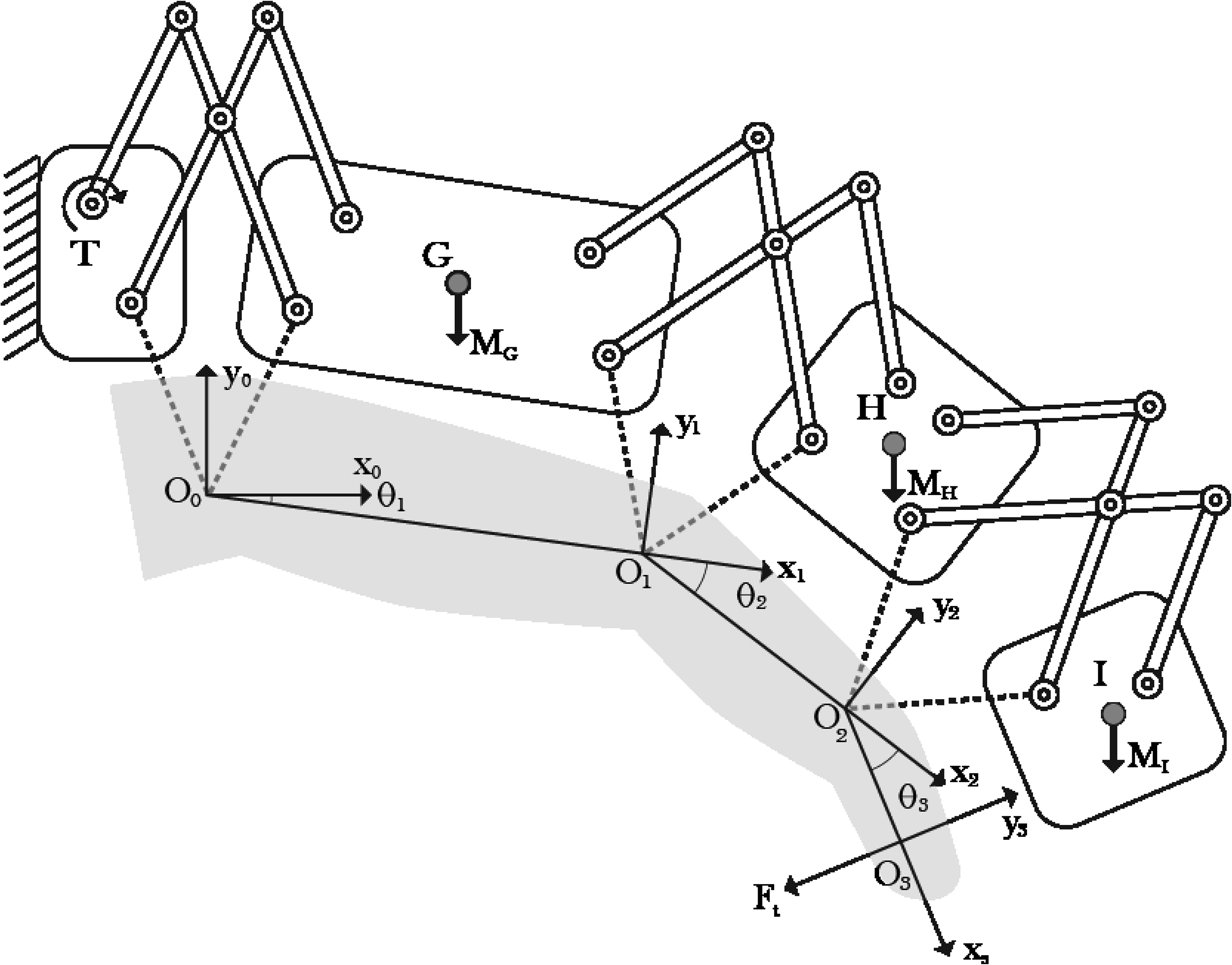
Free body diagram of the exoskeleton mechanism.
The mechanism was designed with only one DOF, so that the angles

The virtual work principle was used in order to calculate the motor torque for the exoskeleton mechanisms by using the following equation

where
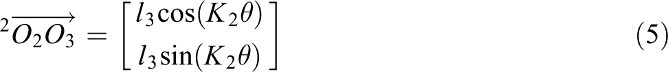
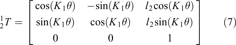
To determine the position and orientation of the mobile frames O 1, O 2, and O 3, transformation matrices are used. Considering l 1, l 2, and l 3 as the length of the PP, MP, and DP, respectively, the position vectors and the orientation matrices of the mobile frames are calculated as follow


The virtual work carried out by the feedback force on the user fingertip Ft is defined by

and considering that the force is applied at the point O 3, the extended position vector for this point is

where
The applied force over the user’s finger is perpendicular to the DP, so a unit vector perpendicular to the x-axis of the third frame (

By obtaining the derivative of vector

where
The virtual work developed by the gravity force is described by

where
Because the mechanical phalanxes were modeled in a symmetrical configuration, the center mass is in their geometrical center. If the distance between the user phalanx and the geometrical center of the mechanical phalanx is denoted by h, the center mass vector of each mechanical phalanx with respect to their respective frame is


The mapping of these vectors to the global origin O 0 can be done by the corresponding transformation matrix as


where
By developing equation (13), the following equation is obtained

The virtual work generated by inertial forces is

where IG , IH , and II are the mass moment of inertia of the mechanical phalanxes.
By developing the algebraic calculations using Mathematica, the virtual work done by inertial forces is described by

where α is the second time derivative of
The required motor torque can be obtained from equation (2) as

Equation (23) was numerically evaluated with the parameters value presented in Table 3. A MATLAB program was developed in order to find the motor torque as a function of the force Ft
and the angular position
Numerical parameters for the dynamic model.

Based on this value, a Micro Metal Gearmotor HPCB 12 V by Pololu with a gear reduction ratio
Exoskeleton instrumentation
Sensors and motor drivers
The main functions of the instrumentation subsystem are sensing the feedback force on the user’s fingertip, detecting the fingers’ angular position, and performing real-time communication between the haptic exoskeleton and the computer.
In order to sense the feedback force on the user’s fingertip, force sensitive resistor (FSR) model SEN-09673ROHS by InterlinkElectronics is selected. This kind of sensor varies its electrical resistance depending on how much pressure is being applied on the sensing area. A voltage divisor circuit is necessary for conditioning the signal sensors. The data relating to implementing the signal conditioning circuit and the sensor response curves were consulted in the sensor data sheet.
To measure the finger’s angular position, magnetic encoders were coupled to the micromotor’s shaft. These encoders use a magnetic disc and hall effect sensors to provide 12 counts per revolution of the motor shaft. The encoders operate from 2.7 V to 18 V and provide digital outputs that can be connected directly to a microcontroller or another digital circuit. In addition, as a redundant measurement, a potentiometer was coupled to the input link of each mechanical finger.
For the velocity and direction control of the motors, the Pololu MC33926 dual brushed DC motor driver was used. This motor driver is a breakout board featuring two freescale MC33926 H-bridge integrated circuits and can supply up to almost 3 A continuous current per channel to two brushed DC motors at 5–28 V. It works supporting ultrasonic (up to 20 kHz) pulse width modulation (PWM) and features current feedback, under-voltage protection, over-current protection, and over-temperature protection.
Signals acquisition and processing
The exoskeleton must be able to send the sensors’ signal to the control device (a PC) and receive the information required to control the actuators from it in real time. The programming was developed in MATLAB Simulink and the Real-Time Windows Target toolbox. The hardware used for data acquisition was the PCI-6024e card by National Instruments® which is compatible with MATLAB Simulink. The signals acquisition is carried out in MATLAB Simulink by using analogical and digital input/output blocks. This instrumentation and data acquisition system must be able to communicate with the mobile robot for its teleoperation as described in the next section. A schematic diagram of the interconnection of the instrumentation and data acquisition system elements is presented in Figure 8.

Schematic diagram of the interconnection of the instrumentation and data acquisition system elements.
The interface communication needs to acquire the signals from the FSR, the micromotors encoder, the mechanical finger potentiometer, and the adjustment potentiometer and to generate the PWM signals to control the micromotors. Therefore, a nine data bus was used for each mechanical finger: two lines for the voltage input, five lines for sensor lectures, and two lines for actuator control.
Mobile robot and hardware communication
The teleoperation of a mobile robot based on the LEGO Mindstorms NXT® kit was proposed as an application case for the two-finger exoskeleton. The flexion and extension finger movements are mapped in forward and turning commands to provide the mobile robot with mobility. The presence of obstacles detected by the robot is communicated to the exoskeleton in the form of force in order to increase the user’s telepresence.
The mobile robot structure is based on the Castor Bot model described in detail by Parker. 31 The robot has an ultrasonic sensor for obstacle detection, two servomotors which provide the input power for the robot movement, a castor wheel for the stability of the robot structure, and the NXT brick for the robot control. The assembled robot is shown in Figure 9.

Castor Bot built with the LEGO Mindstorms NXT.
The control of the mobile robot was programmed using the version 2014a of MATLAB Simulink. For this, the installation of the LEGO Mindstorms NXT complement for MATLAB is necessary. This complement allows for the autonomous control program execution in the NXT brick or simultaneously with Simulink.
The main problem with regard to communication between the NXT brick and the data acquisition card is the use of different Simulink libraries; therefore, it is not possible to execute the respective programs simultaneously. To solve this problem, the NXT brick was programmed to work in an autonomous mode. The NXT brick program only receives the measurement of the angular position of each user finger and sends the signal of the ultrasonic sensor and the angular position of each robot wheel to the PC. The communication between the PC and the NXT brick is carried out by a Bluetooth adaptor in the PC and the Bluetooth integrated in the NXT brick. In order to start the communication, it is necessary to configure the NXT brick as a master device and automatically connect it to the PC when the execution of the NXT brick program and the model simulation start.
The following is a summary of the logic required for the mobile robot control:
Reading the robot sensors.
Receiving data from the PC by the Bluetooth communication.
Determining the robot commands (forward, turning, and stop) depending on the received data and actions being carried out.
In case of an imminent collision (detected by the ultrasonic sensor), the mobile robot is stopped.
The distance measured by the ultrasonic sensor and the angular position of the robot wheels is communicated by Bluetooth.
The received data are displayed on the NXT brick’s liquid-crystal display screen.
The program developed in Simulink is presented in Figure 10. It is important to mention that the program was divided into subsystem blocks in order to have the model in a more compact form. The sampling times of the encoders and ultrasonic sensor are the same so that Bluetooth communication can be carried out. The time for the reading velocity of the ultrasonic sensor is limited, with a minimum sampling time of 0.04 s.
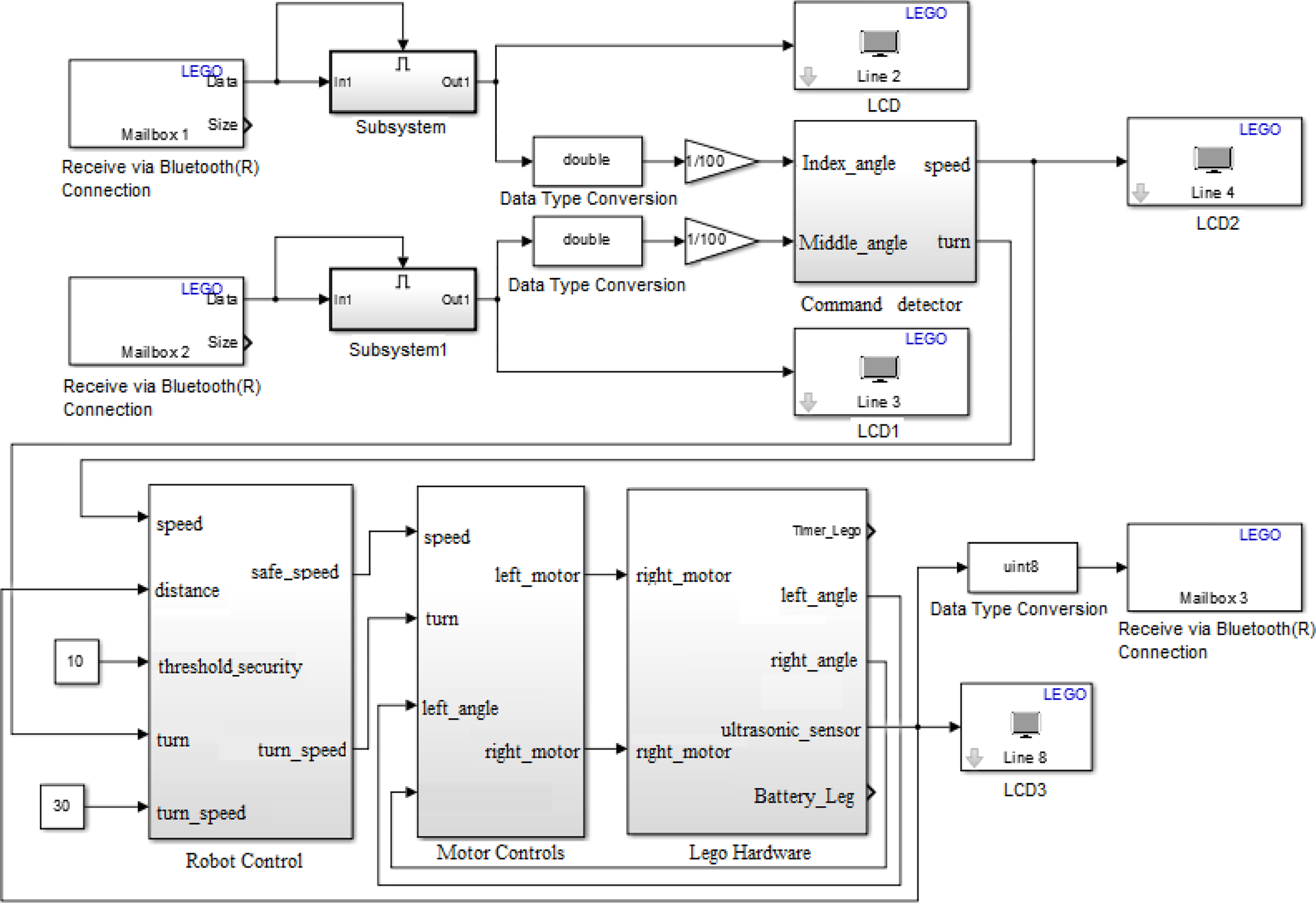
Simulink program for the mobile robot control.
Robot teleoperation
The motion commands forward, stop, right turn, and left turn are defined for the mobile robot control. These commands are mapped from the user’s finger movements in the following manner: the simultaneous flexion of both fingers is converted into the forward command, the complete extension of both fingers is mapped to the stop command, the flexion of the middle finger and the extension of the index finger (of the left hand) are converted into the left turn command, and finally, the flexion of the index finger and the extension of the middle finger (of the left hand) are interpreted as the right turn command. In Figure 11, the exoskeleton on the user’s hand with the extended fingers is shown.

Two-finger exoskeleton on the user hand.
The application is divided into two main problems:
Measuring the angular position of the user fingers. Set the communication by Bluetooth to send the fingers’ angular position to the mobile robot in order to generate the motion commands and to receive the information from the ultrasonic sensor. At the same time, it is necessary to detect the motion of the user’s fingers and allow the exoskeleton to follow this motion.
Translate the information of the distance detected by the ultrasonic sensor in the feedback force over the user’s fingers.
Based on these main problems, two operation modes are generated for the exoskeleton: the follower mode and the force feedback mode, which are described below.
Follower mode
When the exoskeleton is connected to the micromotors, the force that the user needs to exert over the exoskeleton in order to move the mechanical phalanxes is considerable. For this reason, it is necessary to detect the user’s finger motion in a such way that the exoskeleton follows that motion and the user is able to move the mechanical phalanxes with minimal effort. It is important to mention that the motion of each mechanical finger of the exoskeleton is independent and they are controlled separately.
To detect the user’s finger motion, the force sensor placed on the point at which the exoskeleton is in contact with the fingertip was used. The exoskeleton rest position is defined when the fingers are totally extended. In this position, the user’s fingertip is not in contact with the force sensor, so the exoskeleton must stay in a resting position. When the user’s fingertip is in contact with the mechanical finger, the exerted force is measured and if this force exceeds a certain predefined threshold, the micromotors start the exoskeleton flexion motion in order to reduce the user’s effort for that movement. In the case of a reduction of the force level under the threshold but with the user’s fingertip still in contact with the mechanical finger, the exoskeleton stays in a resting position waiting for the user’s action. If the user tries to extend the finger, the contact with the mechanical finger is lost. In this case, the micromotors start the exoskeleton extension motion in order to reduce the user’s effort.
As the exoskeleton control is based on the force regulation over the user’s finger and the finger’s angular position is not taken into account (this angular position is used for mobile robot motion control), a motion limiter is added in order to avoid the exoskeleton moving out of its workspace.
The motion limiter transmits the control signal if the exoskeleton is inside the workspace. When the exoskeleton moves out of the workspace, the following two scenarios can take place: the control signal is transmitted if this signal leads the exoskeleton inside the workspace or the control signal is blocked if the signal takes the exoskeleton out of the workspace.
The blocks belonging to the LEGO Mindstorms NXT for MATLAB complement use identifiers (mailbox) to select the data obtained from the Bluetooth transmission and for their use inside the Simulink model. The data sent by the Bluetooth communication are carried out with the Packet Output block from the Real-Time Windows Target toolbox. By means of a mux block, the data are united to generate a vector which will be sent by the serial communication (see Figure 12). It is important to mention that the NXT brick and the PC must be paired in order to use the Packet Output block. For this pairing, a standard serial port in the PC is created for data transmission.

Block diagram for data sent by Bluetooth.
The data sent by the NXT brick are received by the block set, as shown in Figure 13, in which the packages are separated, and the ultrasonic sensor measurement and the angular position of the mobile robot motors are obtained. A derivative-filter block is applied to the obtained motors’ angular position in order to obtain the velocity.

Block set to data reception by Bluetooth communication.
The Packet Input block is used to receive the data from the Bluetooth communication. The control of the exoskeleton micromotors requires a PWM signal which is carried out by a PWM Generator block. By using a carrier frequency of 1000 Hz for the PWM, the micromotors vibrate when the control signal is close to zero. This is because the voltage polarity is maintained for a sufficient amount of time to invert the rotation direction between positive and negative values. For this reason, the PWM output is limited so that the output is zero if the control signal is close to zero, thereby avoiding the micromotors vibrating and overheating.
The calculation of the mobile robot motor’s position by the encoders’ measurements is carried out by flanks detection. The positive and negative flanks of channel B are detected and compared with the logic value of the channel A. The results of these comparisons are converted into double data to be added to them and to carry out the pulse counting, increasing the pulse number in one direction and decreasing it in the opposite direction. This value is stored to preserve the counting and it is multiplied by a conversion factor to obtain the motors’ angular position in degrees.
Force feedback mode
The force sensor generates a logarithmic signal as a function of the applied force. A voltage signal from 0 V to 3 V for forces between 0 N and 5 N is generated by a designed electric circuit. To transform the received distance from the ultrasonic sensor of the mobile robot in a feedback force, a distance range in which the feedback force acts is defined. This range is from
In order to avoid the distances out of the defined range affecting the control signal behavior, the distance signal obtained from the ultrasonic sensor is saturated so that there are no negative values. In this way, we guarantee that the feedback force starts to act in
The Feedback Signal subsystem input is the distance measured by the mobile robot ultrasonic sensor and acquired by the Bluetooth communication, as can be observed in Figure 14.

Data reception in force feedback mode.
By controlling the two exoskeleton fingers independently, the feedback force persists while the mobile robot is near to collision regardless of whether the robot is receiving the command to go forward or to turn to avoid the collision. To solve this problem, the angular position of each finger is communicated with each other to know whether the mobile robot is trying to go forward or to turn, and based on this information, enable or disable the feedback force. In Figure 15, the controller subsystem for the force feedback mode is presented.

Controller subsystem in force feedback mode.
Finally, the complete Simulink model for the index finger in force feedback mode is shown in Figure 16.
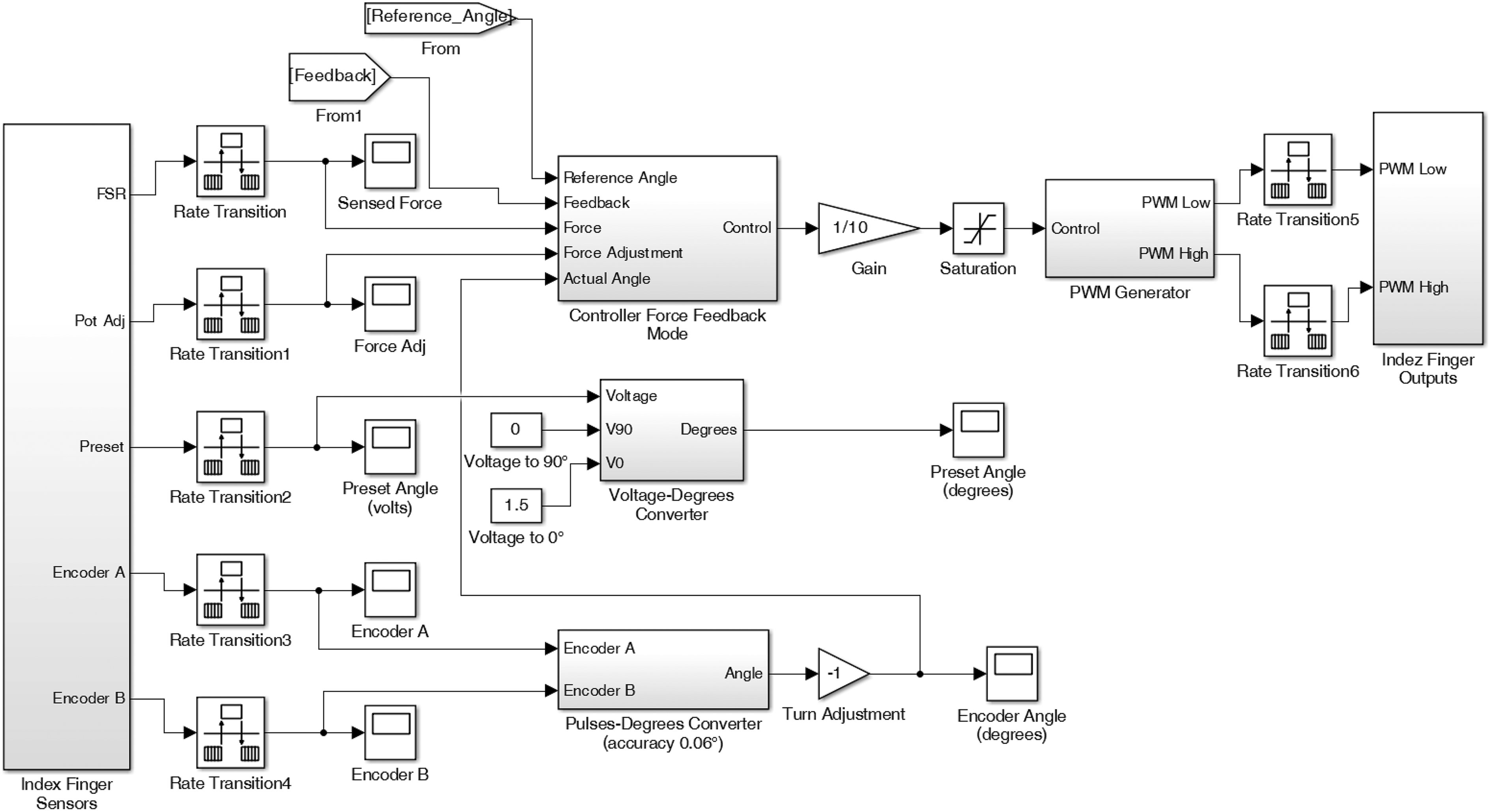
Simulink model for the index finger in force feedback mode.
Experimental results
A haptic exoskeleton for index and medium fingers was obtained as the result of the integration of mechanical, instrumentation, and control subsystems as described above. The complete prototype and the mobile robot are presented in Figure 17.

Haptic two-finger exoskeleton and mobile robot.
To evaluate the correct performance of the complete system, three tests were carried out as follows:
Forward test: The mobile robot moves in relation to the angular position of the user’s fingers.
Turning test: The mobile robot rotates on its own axis in relation to the angular position of the user’s fingers.
Force feedback test: The distance measured by the mobile robot ultrasonic sensor is communicated to the user as a force over the fingertips.
Forward test
This test was performed with the robot on a flat surface without the presence of obstacles around it. The interaction carried out with the exoskeleton consisted of movement in both fingers in maximum flexion and then gradual movement in extension in order to change the forward mobile robot velocity. In Figure 18, the angular position of the user’s fingers and velocity of the mobile robot’s motors are presented. As can be observed, when the angle of both fingers is increased simultaneously, the velocity of the motors is also increased in the same direction, meaning the mobile robot carries on with an increasing velocity. When the fingers stay completely flexed, the motors’ velocity stays constant and with the same value, the mobile robot is moving forward with the maximum velocity. If the angle of the fingers is decreased, the velocity of the motors is also reduced. Finally, when the fingers are fully extended, the mobile robot stops its movement. The delay between the angle of the finger and the velocity of the motor observed in Figure 18 is induced by the filter-derivative block used to obtain the velocity of the motor from the encoder’s measurements.

Angular position of the user’s fingers and velocity of the mobile robot’s motors in forward test.
Turning test
In this test, the interaction carried out with the exoskeleton consisted of flexing the index finger while the middle finger stays extended and then completely extending the index finger and flexing the middle finger. Finally, both fingers are fully extended to their resting position. In this case, the velocity of the left motor is increased in a positive sense and the velocity of the right motor in a negative sense when the index finger is flexed and the middle finger stays extended, as can be observed in Figure 19. This means that the mobile robot keeps turning to the right. When the index finger is extended and the middle finger is flexed, the velocity of the left motor is increased in a negative sense and the velocity of the right motor in a positive sense. This is mapped in a constant left turning motion of the mobile robot.

Angular position of the user’s fingers and velocity of the mobile robot’s motors in turning test.
A video with experimental results for the forward and turning tests can be consulted in the study by Aragon. 32
Force feedback test
In this test, the mobile robot moves on a flat surface with the presence of an obstacle to be detected by the ultrasonic sensor. The mobile robot is controlled by the exoskeleton as described in the other tests, but in this case, the distance detected by the ultrasonic sensor is communicated to the user by a force exerted by the exoskeleton on the fingertips. In Figure 20, the angular position of the user’s fingers and the velocity of the mobile robot’s motors during the force feedback test are presented. As can be observed, in the first 4 s of the test, both fingers are flexed to provide the mobile robot with a forward movement and then the fingers are extended to stop the mobile robot.

Angular position of the user’s fingers and velocity of the mobile robot’s motors in force feedback test.
In Figure 21, the signals of force sensors and the measurement of the ultrasonic sensor are shown. In Figure 21, an increase in the force over the user’s fingertips when the sensed distance decreases is observed. When the distance reaches a minimum value (around 12 cm), the feedback force gets a maximum value which inhibits the user continuing with the flexed fingers and the user is then forced to extend the fingers stopping the mobile robot, as can be observed in the final part of Figure 20. As described in previous sections, in this situation, the only alternative for the mobile robot motion is to turn to avoid the obstacle before the forward command is available. An experimental test in force feedback mode of the exoskeleton can be seen in the study by Aragon. 33

Signals of the force sensors and the measurement of the ultrasonic sensor in force feedback test.
Conclusions and future works
In this article, the complete development of a two-finger exoskeleton and its application for a mobile robot teleoperation was presented. The total weight of the exoskeleton with sensors and electronic parts is 270 g which represents a lighter device in comparison with that reported in the consulted literature. Moreover, the developed device complies with the desired characteristics relating to kinematic compatibility with the human hand (avoiding mechanical interferences) and the ranges of motion. As previously mentioned, one of the main challenges in teleoperated robots is efficient communication between the slave device, the master device, and the user. In this context, subsystems integration plays an important role. In this case, the impossibility of using the LEGO Mindstorms NXT complement for MATLAB and the Real-Time Windows Target toolbox simultaneously represented a serious problem for the correct subsystems integration. This problem was solved by using a Bluetooth communication protocol to run the robot program autonomously and to transmit the data by a virtual serial port to be used by the exoskeleton for its correct performance. Finally, a mobile robot teleoperation was presented as a case study in application, verifying the correct operation according to the specified requirements. The developed integrated system represents an affordable option for experimenting with teleoperated robots in comparison with the reported systems which use expensive commercial haptic devices and slave robotic systems. This characteristic opens up the possibility of using the integrated system in both research and teaching activities.
Based on the obtained results, the following activities are proposed to improve and extend the use of the presented system:
Extend the exoskeleton to five fingers in order to have a wide range of control signals to extend the potential applications of the haptic exoskeleton.
Implement the data acquisition and processing in a portable digital device to eliminate the device’s dependence on a PC and to be able to apply the haptic exoskeleton in a wider range of applications.
Provide the exoskeleton with the capability to adjust to different hand sizes, thereby avoiding mechanical interference between the exoskeleton and the human hand, even with different users.
Footnotes
Declaration of conflicting interests
The author(s) declared no potential conflicts of interest with respect to the research, authorship, and/or publication of this article.
Funding
The author(s) disclosed receipt of the following financial support for the research, authorship, and/or publication of this article: The authors received financial support from PRODEP-SEP, Mexico for publication of this article.