
Abstract
To control industry robots and make sure they are working in a correct status, an efficient way to judge the motion of the robot is important. In this article, an industry robotic motion and pose recognition method based on camera pose estimation and neural network are proposed. Firstly, industry robotic motion recognition based on the neural network has been developed to estimate and optimize motion of the robotics only by a monoscope camera. Secondly, the motion recognition including key flames recording and pose adjustment has been proposed and analyzed to restore the pose of the robotics more accurately. Finally, a KUKA industry robot has been used to test the proposed method, and the test results have demonstrated that the motion and pose recognition method can recognize the industry robotic pose accurately and efficiently without inertial measurement unit (IMU) and other censers. Below in the same algorithm, the error of the method introduced in this article is better than the traditional method using IMU and has a better merit of reducing cumulative error.
Introduction
Wire and arc additive manufacture (WAAM) is an advanced technology based on layer-by-layer deposition principle, which uses arc heat to melt metal wires and gradually forms metal components from lines, surfaces to bodies. The products made by industry robots have the advantage of high efficiency and low cost relatively and can be used to manufacture high-quality large-scale metal components to fit the need of the manufacture of large-sized ships (e.g. carriers), airships, high-rise buildings, and so on.
Motion and pose recognition play an important role in industry robots, since the robots themselves need to know if they are working in a good condition to prevent some dangerous action ahead. However, traditional methods have some problem, which would be not accurate in some conditions.
Motion recognition of robotic system is an important aspect of robotics navigation and self-modification. 1 –6
Industry robots have been used in some complex task content and get acceptable results. 7 However, such huge robots will cause serious problems if they do not work in the right pattern. Some articles combine camera and inertial measurement unit (IMU) together to correct the error caused only by IMU, 8,9 which shows that camera has similar function as IMU that can correct or even replace IMU module. All errors in this article mean absolute error, which is defined by the difference between the expected value and the true value.
Some visual methods to calculate pose of the camera have also been developed, 10 –13 which is known as camera pose estimation, and many fields are used but not robotics monitor. Here, though meeting with some problems that IMU would not come up with, visual methods have some advantage that IMUs do not have. For example, cameras can restore the pose of a robot for a long time by restoring an image captured by camera. However, IMU mainly captures only the value of the accelerated speed, so it cannot restore an exact data of the pose. Only calculating the double integration of accelerated speed will result in serious error of the pose transformation (rotate angle and displacement). The existing articles 14 –16 mainly focus on correction of data collected by IMU using camera. Some articles 17,18 use visual method but put camera outside to capture the camera and extract feature points of the robot, which may not be stable in complex environments such as strong colored light, no matter whether the camera is calibrated or not. Also, this method will meet serious problem of the occlusion, which let this method not suitable for the robotics systems to use.
However, many articles focus only on how to get the parameters more accurate using both visual camera and IMU. In some condition, under the restriction of budget or the design of the robotics system, IMU may not be able to use. For example, when the size of a robot is restricted and cannot afford an additional IMU censer, the article provides a method to do the same kind of job by the visual camera that is fixed to the robot, which might have other functions at the same time. This article is mainly about how to calculate and optimize motion and pose of the robotics system only by a monoscope camera. There are no existing methods like the method proposed in this article.
The advantages of the system proposed by this article are as follows: The whole algorithm only uses visual data captured by cameras. It does not need IMUs or other censers other than a camera, which costs less and decreases the hardware requirement for the robotics system. The algorithm contains the information both long term and short term. Visual method captures the information of position while IMU captures the information of acceleration, second derivative of position. Compared with the traditional method, using vision can repress accumulative error better, especially it can reduce the error during a long time. Some robots with IMUs depend too much on geomagnetic field, which cannot defend high-intensity magnetic field, this system can help IMU to work accurately in such condition. Visual method is more robust in such environment. It works well in the condition that the velocity is not very fast, and the light condition is receivable, which is a common environment in most industry scenes.
Aside from “Introduction” section, the main part will be divided into two sections: motion recognition and pose recognition. After that, several experiments and their results will be presented. The last section will be the conclusion and the discussion of future work.
Robotic motion recognition method based on neural network
Structure of the robotic motion recognition system
When the system is running, it just respects the process from “Preprocess of images captured by CCD camera,” “Feature points extraction and match,” “Euler transform matrix calculation between flames,” and “Motion feature vectors calculation” sections and gets the data of
In actual environment, we do not care about the absolute angle or coordinate of the robotics system or the camera, we just need to calculate the difference or error of the camera to judge if the robotics system works well, according to the motion and pose. The method is based mainly on camera pose estimation, which could calculate the pose and motion of the camera by the image captured by the camera. The process will be detailed in the next subsections, which is rather a robust method in an indoor environment.
Preprocess of images captured by CCD camera
To eliminate the blur caused by the motion of the camera and other factors that may result in the error of the final result, preprocess needs to be done.
The system will be installed into a computer that controls the robot. As shown in Figure 1, the system will be installed into a computer that controls the robot, which is a normal PC instead of a computer used for high-performance computing. As a result, the complexity of the algorithm should not be too high. If the size of the image captured by the camera is too large, or, to say, the resolution of the video is too large, then the performance of the real-time ability will be so low that the result will not be accurate. After the tests, the author recommends the resolution to be about
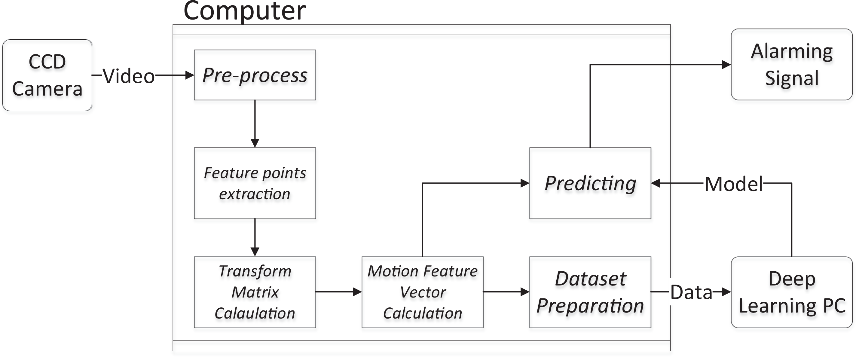
Structure of the robotic motion recognition system.
Feature points extraction and match
To calculate the transform matrix between two flames, firstly, speeded up robust feature (SURF) points need to be extracted. If two feature points are used for a match, they should not be too close. The author defines “too close” as the formula below

where
Euler transform matrix calculation between flames
After the feature points matched, the transform matrix between two flames can be calculated by the following steps


where
During the process, to deal with the problem of the outline value, RANSAC 20 algorithm needs to be applied to make the result more accurate. Actually, the algorithm above does not need too many matches of feature points. So, to cut down the time cost, the author uses only 30 good matches to calculate rotate matrix, which is accurate enough to reach the target.
Till now, the rotate matrix and displacement vector between two flames are determined.
Motion feature vectors calculation
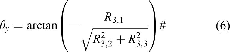
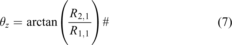
However, the rotate matrix (
The Euler angle can be calculated by

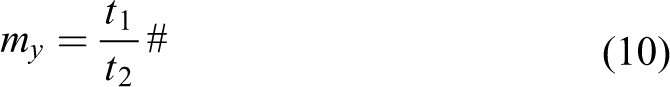
The author defines two values to describe the displacement vector


Feature vector is the assembling of parameters above

Feature vector describes how the robot acts during the flame, the action has direction, so the camera needs to put in an exact position and angle on the robot.
Preparing dataset used for neural network
The motion is consisted of several flames, so only judged by one flame will cause error. The author uses the data of 10 flames to make a judgment. Of course, the value 10 is an experimental value and should be adjusted to different using content.
Due to the difference between the processing time of different flames, the data need to be adjusted to a fixed interval in order to better express a motion. For example, if a duration of flame 1 is 200 µs and another is 400 µs, directly using the feature vectors is not reasonable, and it is better to make flame 2 into two data points.
The algorithm will be described like the code below.
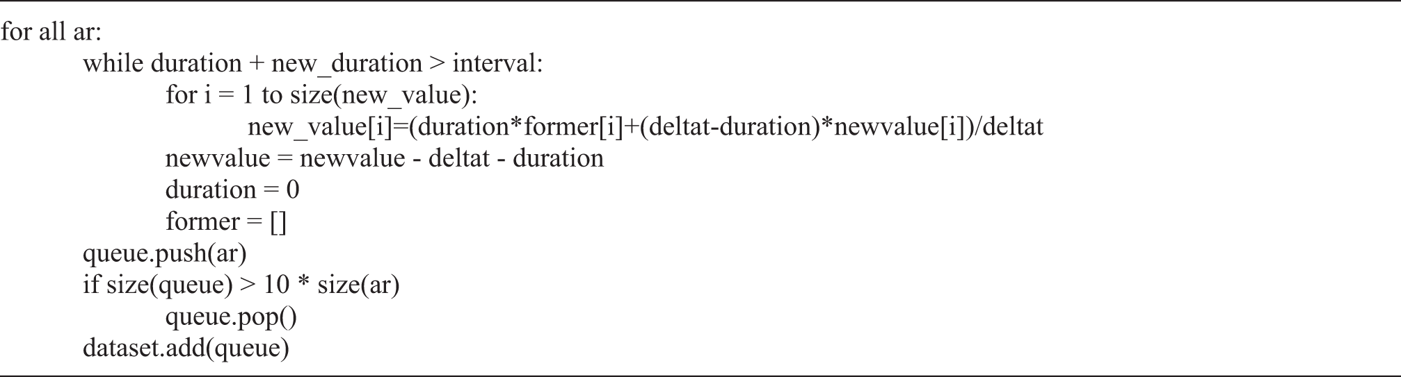

The variables to use across the flames are defined as
To describe the algorithm more clearly, it is a problem of converting continuing time problems to discrete ones. We create a queue to store the Euler transformation and the time interval during the sampling process. The judgments are made by a fixed interval, but sampling data do not come with the same interval. As a result, the data should be added up with weight, which is a time interval in the process. The process is known as integral controller. During one interval, the time is rather short, and the transform is considered to be on average. All in all, the algorithm is designed in the code above.
Predicting using neural network
The input of the neural network consists of a vector of 50 elements, and the output is n dimension vector, which means we need to classify the input into n categories. It is a rather simple classification and it does not need complex networks. By using too complex neural networks, it is easy to meet with overfitting problem. Because the label cannot be obtained automatically, the label may be recorded to use in supervised learning.
The neural network is shown in Figure 2 below.

Structure of the neural network.
The loss is set as L1 distance and the optimizer is SGD optimizer. During the whole learning process, the loss will be passed backward. It is such a simple task that an overly complicated network tends to result in overfitting, so the network only contains input, output, and two hidden layers.
After supervised learning, the network will generate the model, which is able to recognize motion type with the input of motion feature vector real time.
Pose recognition and key flames mapping
Pose recognition is another aspect that camera vision can help IMU to be more accurate. Since IMU can only detect accelerated speed, it may result in an error when using it for a long time without other adjustments. Since robots are mainly used in indoor circumstances, feature points are easy to extract and the problem of light would not affect extracting process.
Key flames recording
Since IMU cannot record the exact pose of a flame or the transform matrix between two flames has an interval of time directly, camera vision is a good method to assist IMU to redirect.
The key flame will be recorded when very few feature points are fitted with current recorded key flames. The record of the data is the pixel coordinate of feature points.
The process is shown in Figure 3.

Flowchart of key flames recording in pose recognition.
Pose adjustment
Since camera vision can better restore the pose of the robot, comparing the accumulative Euler transform matrix at an interval of time, the result will be more accurate.
If the interval is set as 20 s, the system will adjust pose as the interval of 20 s. When detecting a new flame, firstly, its feature points should be extracted. Then, the set of feature points should be tried to match with key flames, if very few feature points are matched (e.g. 10), it is not a good match. After finding the key flame that matches the new flame’s best, Euler transform matrix could be determined (the same method described in “Feature points extraction and match” section). The adjusted pose can be obtained by multiplying the matrix of the matched key flame and the calculated Euler transform matrix.
The process will be shown in Figure 4.

Flowchart of pose adjustment method.
Tests and results
The tests are carried on the KUKA industry robots, as shown in Figure 5. KUKA ArcTech robots are designed for WAAM, which are six-axis robot and can do many actions to do the work. The camera is fixed to the robot and the robots are set in an indoor environment. The camera is connected to a computer, and an alarming signal will be shown on the computer and will automatically check motion and pose of the robot.

Development platform based on KUKA industry robot.
Experiment of motion recognition
To train the model, dataset is needed. The size of the dataset used in the experiment is 19,492. The size of the test set is 1928. Labels contains four categories. The four label types are row rotate, pitch rotate, yaw rotate, and keep stable. The result is shown in Figure 6.
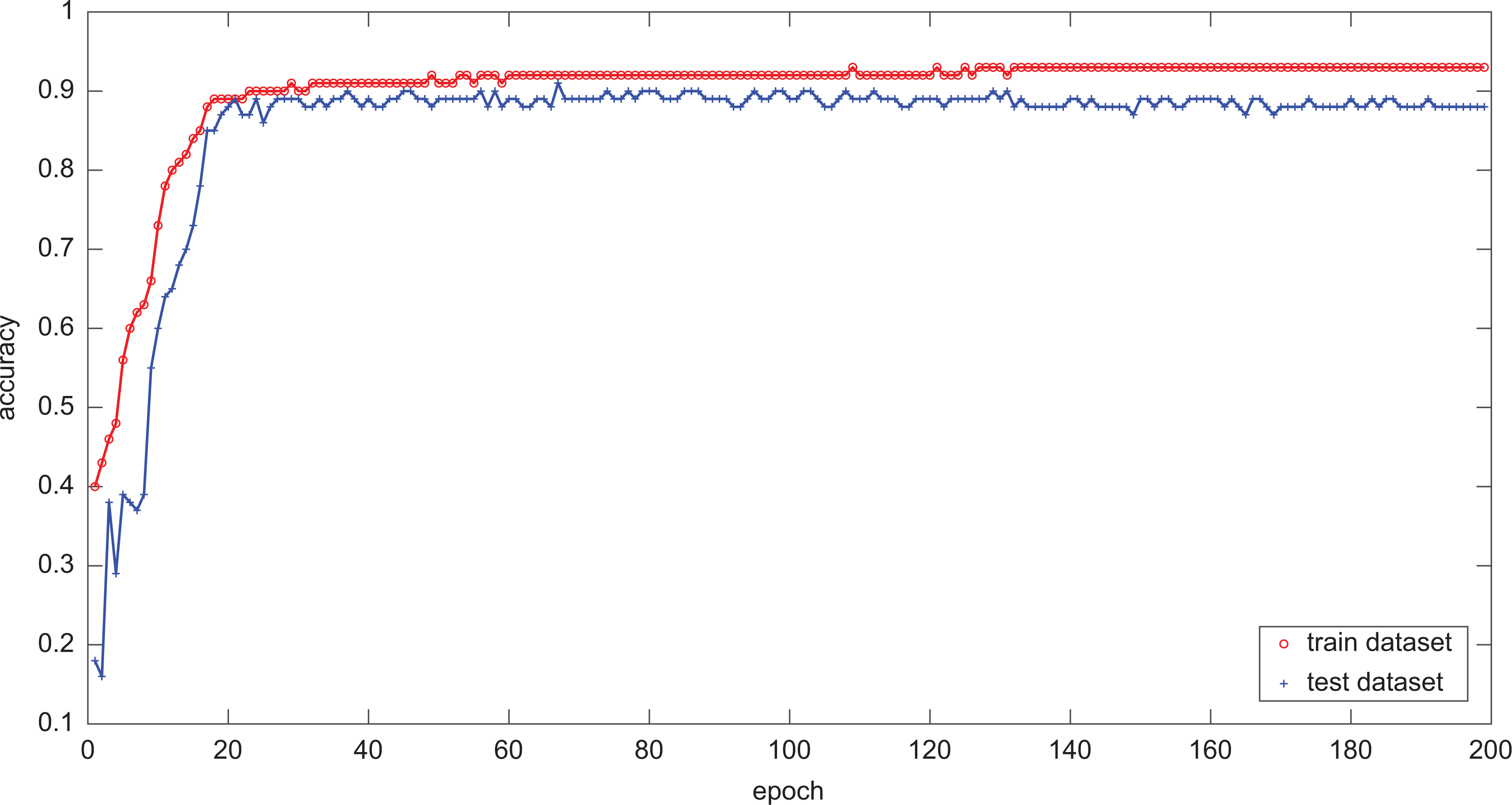
Accuracy of the train dataset and test dataset.
From the figure above, it says that the accuracy of training dataset will be stable at 92%, and the accuracy of test dataset will be stable at 90% after 200 epochs, which is an acceptable result for the system.
Experiment of pose recognition
To test whether the visual method has a better result than just using IMU, the author sets an IMU and visual camera on a robotics device together and let them calculate the pose of the device, respectively. Finally, the device is set to return to its original pose, and the error of the method proposed in this article and error using only IMU will be compared.
However, using raw data of IMU will cause a huge error, which is shown in Figure 7 and must be processed to make it more accurate.

Error comparison between IMU nonprocessed and processed.
The experiment is designed as that we let the camera move and rotate randomly, and back to a same place with the same angle at an interval of some time, the value of the value is the error.
Since the raw data of the data captured by IMU have huge error, here is the comparison between processed data captured by the IMU and vision. The data captured by the IMU have been processed and became more accurate.
From the diagram, it can be seen that the error of the visual method is fixed to a finite range, while the error of IMU will acuminate by the time and need to be calibrated by other methods. The advantage of the visual method is that it can adjust itself automatically because the camera can capture the information of a flame, but the IMU can only censer motion information, which may not be so accurate in the integral process and may cause the acumination of error.
In Figure 8, blue line represents the accuracy of error of the processed IMU captured data. The red line represents that of vision camera captured data.

Error comparison between IMU and vision method. IMU: inertial measurement unit.
Then, we do the same experiments many times. Although the expectation of the error is almost 0, the standard deviation of the IMU method is significantly higher than the visual method, which can be seen from Table 1.
Performance comparison of the proposed method and the traditional method.

IMU: inertial measurement unit.
The reason for this phenomenon is also the disadvantage mentioned in “Experiment of motion recognition” section that the camera can record the information of each flame, but the IMU can only detect the difference between flames, which leads to more error. Camera captures the position information, and the velocity can be calculated by calculating derivative. However, using IMU can only detect acceleration information, and the velocity can be calculated only by the integral method, which will probably cause a larger error, especially when operating time gets longer.
From the result above, we can see that the visual method has the ability to do the pose recognition without IMU and other censers, and works even better when operating time gets longer.
Conclusion
This article presents a motion and pose recognition method based on camera pose estimation and neural networks. It is a new method to depress the error caused by the acumination of IMUs. The experimental results demonstrate that the proposed algorithm can help IMU to be more accurate and do more things than only an IMU can do, such as pose recognition.
The future work is that we hope the system can not only tell if the robot is working well but also the wrong type and give the robot control system advice about how to adjust the robotics system to fix the problem automatically, so that human beings do not need to do these kinds of work.
Footnotes
Author contribution
The author FX contributed equally to this work and should be considered as a co-first author.
Declaration of conflicting interests
The author(s) declared no potential conflicts of interest with respect to the research, authorship, and/or publication of this article.
Funding
The author(s) disclosed the receipt of the following financial support for the research, authorship, and/or publication of this article: This work was partially supported by the National Key Research and Development Program of China [Grant No. 2017YFB1103200], the National Natural Science Foundation of China (Grant No. 41974033), the Scientific and Technological Achievements Program of Jiangsu Province (BA2020004), and 2020 Industrial Transformation and Upgrading Project of Industry and Information Techonlogy Department of Jiangsu Province.