
Abstract
This study considers the problems of manipulators with high coupling, parameter uncertainties, and external disturbances. A six-axis serial manipulator control system based on active disturbance rejection control strategy is proposed without the requirement of the exact dynamic model. First, the operating circuit of the manipulator joint motor is analyzed, and the mathematical model of the direct-current torque motor is established. Second, the components of active disturbance rejection control are designed, and a new nonlinear function is selected to construct the extended state observer and nonlinear state error feedback control law. Then, Kalman filter is introduced into an extended state observer to estimate the disturbance efficiently. Finally, the proportion–integration–differentiation control, traditional active disturbance rejection control, and improved active disturbance rejection control are simulated and compared under the same input signal. The results show that the proposed control strategy has good dynamic performance and uncertain disturbance robustness, which proves the effectiveness of the proposed method.
Keywords
Introduction
In modern industrial production, industrial robots have replaced human beings in many fields owing to their large labor capacity, high precision, high repeatability, and ability to work in harsh working environments. As a robot with obvious structural characteristics, the most basic function of multi-axis serial manipulator is to receive instructions and complete positioning and trajectory tracking. 1 –4 The positioning and trajectory tracking control of the multi-axis tandem manipulator can be summarized as follows: From the robot dynamics, the driving torque of the manipulator can be controlled, so that the position and attitude of the manipulator can be quickly and accurately converted according to the requirements of the task. A stable closed-loop system can be formed to set the joint state tracking value as quickly as possible to complete the task. 5 At present, conventional control strategies for a multi-axis linkage manipulator include proportion–integration–differentiation (PID) control, neural network control (NNC), adaptive control, sliding mode control (SMC), and robust control. 6 –10 However, because of the complex mechanical structure of the mechanical arm, different joint-connecting rod systems interact with one another and are highly coupled. The whole system presents nonlinear and strong coupling characteristics, which lead to difficulties for conventional control strategies to control the system quickly and precisely. 10,11 For example, PID control belongs to the single-degree-of-freedom (DOF) control; specifically, the adaptive ability of the control system is insufficient when the manipulator’s own parameters change, and the control effect is poor when the manipulator moves fast. However, NNC lacks systematic and standardized methods for constructing neural network, which requires considerable time training and has no clear physical meaning. System stability and other problems are also difficult to prove in a neural network. Similarly, the adaptive control is a time-varying nonlinear system with low control accuracy, and it is difficult to meet the control requirements. A sliding mode adaptive fractional fuzzy control is provided in this article to achieve the trajectory tracking control of uncertain robotic manipulators. 12 The main idea of this work consists in using fractional input to control complex integer-order nonlinear systems. But, it is necessary to consider how to improve the proposed method such that the tracking errors are asymptotically stable. Existing control methods of the manipulator mostly rely on the mathematical model of the system. However, establishing an accurate mathematical model is difficult due to the complex model of the manipulator control system and the influence of some unknown factors. Therefore, an attempt is proposed to introduce the active disturbance rejection control (ADRC) technology, which can help achieve decoupling control of the multi-joint torque output of the robot and provide a new method for coordinated control of the multi-axis manipulator by not relying on the accurate model of the controlled object.
In contrast to previous methods, ADRC technology is a kind of nonlinear control method that has only been developed in the last 20 years. Originally proposed by Mr. Han, ADRC has high control accuracy and can solve control problems quickly and without overshoot because it does not rely on the precise mathematical model of the object itself. It shows great potential in the fields of fast tool servo-control, micro electro mechanical system (MEMS) sensors, time-delay systems, and spacecraft attitude control. 13,14 Therefore, many scholars at home and abroad have studied ADRC and achieved positive results. For example, a robust controller based on adaptive extended state observer (ESO) was proposed for the precise position tracking control of a rodless cylinder with strong static friction. The proposed controller combined the advantages of SMC and linear ADRC and improved the response speed and positioning accuracy of the system. 15 Chen et al. 16 proposed a compound path following the controller that allowed small fixed-wing drones to follow a predefined path. The controller design adopted the hierarchical control structure, and the inner-loop controller design based on the active disturbance suppression control concept was adopted. The core part of the outer-loop controller was designed on the basis of the Lyapunov stability theorem to generate the desired route of the straight line. To go a step further, Song et al. 17 used ADRC technology to study the nonlinear uncertainties of hypersonic reentry vehicle when the actuator was saturated. Simultaneously, the convergence of the nonlinear ESO and the stability of the closed-loop system were studied. A complete mathematical model of the eight-DOF semi-tracked vehicle was established, and a road excitation model that considered the relationship between vehicle and artillery was analyzed. An ADRC for each channel of six subsystems was proposed through the decoupling of the original system. Total interference was estimated and canceled by switching ESO and linear state error feedback. 18 An adaptive controller was designed on the basis of the change of ADRC framework to solve the trajectory tracking problem of Delta robot with an uncertain dynamic model. 19,20 The application of nonlinear ADRC method to uncertain nonstationary control systems was discussed. The key idea was to use ESO to estimate the state and uncertainty in real time and apply dynamic inversion to deal with the non-control problems. The practical convergence of the closed-loop systems could be achieved. To a large extent, the results obtained extended ADRC method to more general nonlinear systems. 21 These studies show that ADRC technology can be used to actively extract disturbance information from the input and output signals of the controlled object and then eliminate it with the control signal as soon as possible, thereby significantly reducing its influence on the controlled quantity. For multi-axis system, the multi-axes coupling can be regarded as internal disturbance by ADRC technology, and the ESO can be used to estimate and compensate, so as to eliminate the disturbance. Simultaneously, ADRC technology has been maturing and its application scope has been expanding.
However, owing to the severity of the application environment and the complexity of the controlled object, some researchers have improved ADRC by considering different environments and controlled objects. For instance, the hydro-turbine speed governor system was studied. 22 On the basis of the original scheme, a new ADRC and fractional-order PID hybrid control scheme was designed, which overcame the disturbance of random noise and could be adapted to nonlinearities and unknown dynamics of the hydro-turbine speed governor system. To achieve precise decoupling and interference compensation, an ACO-based ADRC for induction motors was proposed. ant colony optimization (ACO) was used as the automatic tuning mechanism of ADRC; it reduced the dependence of ADRC on parameters and was more robust than traditional ADRC. 23 Xie et al. 24 addressed the backstepping ADRC for trajectory tracking of underactuated autonomous underwater vehicle. Following this, reduced-order linear ESOs are designed to estimate and compensate for the uncertainties that exist in the model and the external disturbances. Without the influence of actuator saturation and failure, the usefulness and robustness of the proposed controller were proved in the presence of internal parameter uncertainties and external time-varying disturbances. A composite ESO based on nonlinear sampled data was proposed to estimate the overall impact of unmodeled nonlinearity and disturbance. Then, an ADRC scheme for pneumatic muscle actuator was constructed, which provided good conditions for the stability of the control system with saturated actuator. 25 An ADRC was designed for at the position control of the finger of a two-joint robot driven by pneumatic artificial muscle, which solved the decoupling problem of double input and double output and achieved stable and high-precision control. 26 Furthermore, a nonlinear ADRC controller was designed for trajectory tracking of robotic manipulators. The robustness of this method to parameter uncertainties and disturbances was discussed. Compared with robust passivity control, this control method has better tracking performance and lower energy consumption. 27 An improved ADRC method for high-precision trajectory tracking of six-DOF robots based on the two methods was proposed. A single-joint control strategy was used to design the decoupling control law, which had good anti-jamming performance and robustness and could perform high-precision trajectory tracking control. 28 In view of the above situation, the traditional ADRC cannot meet the existing control requirements. Most researchers used the method of changing the structure to improve the ADRC and realize the stability control of the system. The nonlinear function of ADRC can also be improved, and the function with good smoothness and convergence can also improve the control performance.
ADRC technique is used in this study to compensate for the torque acting on the joint, and a six-axis serial manipulator control system based on ADRC strategy is designed, which is applied to direct current (DC) torque motor. First, the joint structure of the six-axis serial manipulator is analyzed, the mathematical model of DC torque motor is obtained, and the control characteristics of the motor are analyzed. Then, a nonlinear function with enhanced conductibility and continuity near the origin and break points is designed, and the components of ADRC are constructed to verify the performance of each part. Meanwhile, Kalman filter is introduced into ESO. Finally, the effects of different input signals on the rapidity, stability, and accuracy of the multi-axis linkage control system are analyzed through experimental simulation. The results show that the proposed ADRC can well realize the positioning control and tracking control of multi-axis linkage manipulator, and the structure is simple and easy to establish.
The remainder of this article is organized as follows. Mathematical model of six-axis serial manipulator is introduced in the second section, and the formulation of ADRC and stability analysis of ESO are given in the third section. In the fourth section, the ADRC with Kalman filter is designed. Next, the simulation examples are provided to illustrate the effectiveness of theoretical analysis in the fifth section. Finally, conclusions are drawn in the last section.
Mathematical model of six-axis serial manipulator
The six-axis serial manipulator is composed of multiple moving or rotating joints and connecting rods. The connecting rods are connected by a series of motion pairs, mainly rotating and sliding pairs. The continuous motion of the manipulator can be achieved by controlling the connecting rods with the motor mounted on the joint. In addition to the base and end of the manipulator, motion pairs are located at both ends of the other rods.
Figure 1 shows the mechanical structure diagram and joint numbers of the six-axis serial manipulator. The concentric circle indicates that the axis direction is perpendicular to the paper surface, whereas the diamond shape refers to the axis direction parallel to the paper surface. The motor types of each joint are shown in Table 1.

Mechanism diagram of the six-axis manipulator.
Types of joint motors.

The base is the fixed part of the manipulator and is connected to joint 1 by a connecting rod. Joints 5 and 6 represent the wrist part of the manipulator, which can perform pitching and lateral rotation operations. They have two DOFs, and so here they are represented by two joints.
Dynamic model of six-axis serial manipulator
The dynamic analysis of the manipulator can realize the real-time control of the manipulator to achieve better dynamic performance. Lagrange method is used to establish the dynamic equation of six-axis serial manipulator. The restrictions of the six-axis serial manipulator are as follows: (1) It is assumed that all the components of the manipulator are rigid. (2) The friction between the components is ignored.
According to the definition of Lagrange, the Lagrange function L is expressed by the difference between the kinetic energy K and the potential energy P of the system, that is, L = K − P, where K and P are expressed by the generalized coordinates q.
The Lagrange function L is used to describe the dynamic state equation of the system as follows

where qi
is the generalized coordinate of joint i,
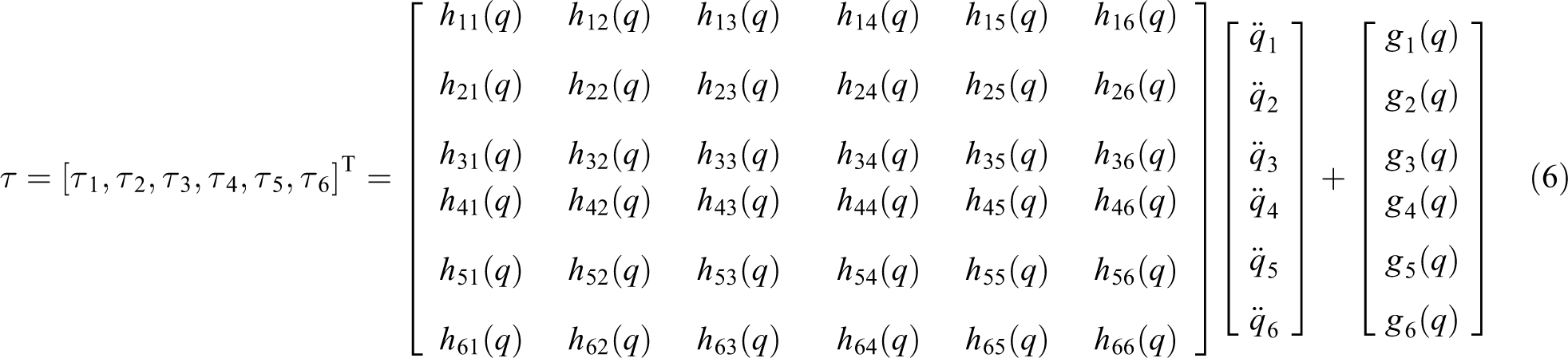
The dynamic model of the manipulator is as follows

In the formula, q,
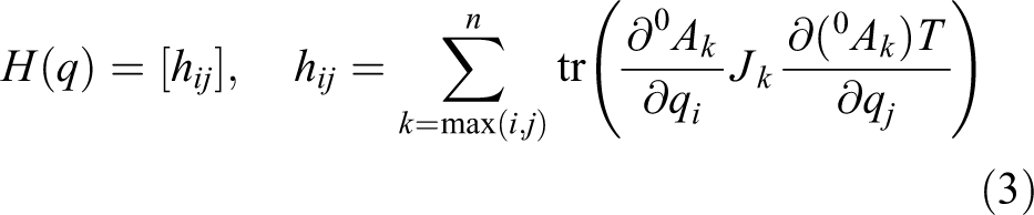


where
Neglecting the influence of centripetal force and Coriolis force on the system, a simplified dynamic equation can be obtained as
Meanwhile, all movements are determined by the position, velocity, and acceleration of each joint. Thus, the joint is the most important part of the entire structure. Coupling between joints can be effectively compensated by the ADRC control of the manipulator. Therefore, completing the positioning control of the manipulator is equivalent to analyzing the manipulator joint.
Mathematical model of the DC torque motor
Figure 2 shows the equivalent circuit of the DC torque motor in operation.
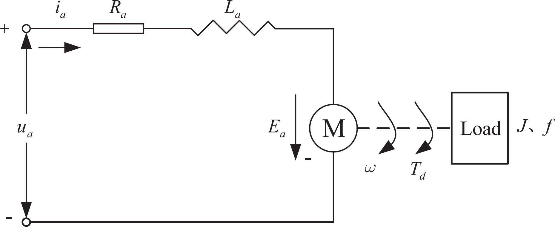
Equivalent circuit for motor operation.
According to the working principle of the DC torque motor and Kirchhoff’s law, the DC motor has four balance equations.
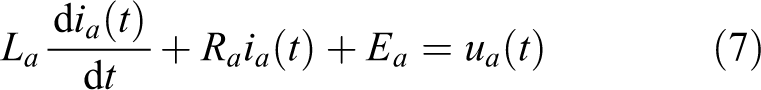
The voltage balance equation of the armature circuit is as follows
The electromagnetic torque equation is as follows

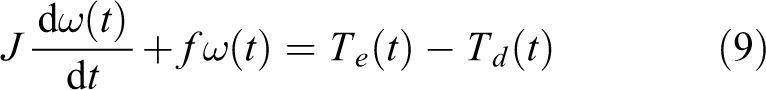
The torque balance equation is as follows
On the basis of the electromagnetic induction relationship, we can obtain the following equation

where ia , Ra , and La are the armature circuit current, resistance, and inductance, respectively. Ea is the back electromotive force of the motor, ua is the armature voltage, and Te is the electromagnetic torque generated by the armature current. Ce and Ke are the motor torque coefficients. Ca and Ka are the back electromotive force coefficients. n is the motor speed, ω is the motor angular speed, J is the moment of inertia, f is the viscous friction coefficient, and Td is the load torque with interference factors.
According to the four balance equations, the transfer function between output ω and input ua of the DC torque motor can be established using the Laplace transform under the zero initial condition
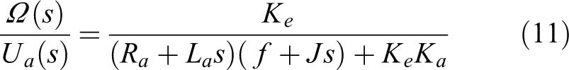
On the basis of equation (11), the structure of the DC torque motor can be established, as shown in Figure 3.

DC torque motor structure. DC: direct current.
The dynamic mathematical model of the motor position can also be obtained as
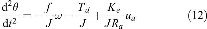
where θ is the angle at which the motor turns.
Let

Given the similar joint structures of the manipulator, the 55LYX02 DC torque motor is selected for analysis. Table 2 shows the motor parameters.
DC torque motor parameters.

EMF: electromotive force.
Combined with the parameters of the DC torque motor, the transfer function model established by equation (11) is simulated, and the speed response curve of the motor under step input is obtained, as shown in Figure 4.

Motor speed response waveform.
As shown in Figure 4, the DC torque motor has fast speed response and good dynamic characteristics and can be continuously operated at low speed or completely stalled. This motor is widely used in high-precision speed and servo systems, and it is suitable for the selection of robot arm joints.
ADRC design
ADRC can estimate the disturbance in real time and control the output by compensating for the disturbance. ADRC has four main components. (1) Tracking differentiator (TD) is used to arrange the transition process, extract the differential signal, and track the output signal. (2) ESO is the core of ADRC and is used to estimate the effects of the order variations, unknown external disturbances, and unmodeled dynamics of the system, as well as to compensate in feedback. (3) Nonlinear state error feedback (NLSEF) control law combines the tracking output signal with the state feedback signal in a nonlinear manner to provide stable and effective output signals. (4) Disturbance compensation device (DCD) controls and corrects the untreated input by compensating for the disturbance.
Tracking differentiator
TD is an important part of ADRC. The main purpose of the proposed scheme is to solve the problem of the reasonable extraction of the tracking and differential signals. TD can arrange the transition process, obtain a smooth input signal, and establish fast tracking without overshoot to solve the contradiction between overshoot and rapidity. The specific algorithm is as follows

where r
0 is the speed factor, h
0 is the filter factor, and h is the sampling step size.

The tuning of TD parameters mainly depends on the speed factor r
0 and filter factor h
0. The values are

(a) Step response curve. (b) Sinusoidal response curve. (c) TD filtering effect comparison chart. TD: tracking differentiator.
Figure 5 illustrates that TD achieves smooth transition to the input signal. Combined with the fastest speed control function, fast tracking and synchronous differential output can be achieved while ensuring substantially no overshoot, which can effectively reduce noise amplification signal and steady-state error. In Figure 5(a), TD completes fast tracking within 0.62 s after the step signal is added without overshoot. Figure 5(b) efficiently reflects the outstanding performance of TD.
Extended state observer
ESO is the core part of ADRC. When the idea of the state observer is used, the disturbance effect that influences the output of the controlled object is extended into a new state variable, and a special feedback mechanism is used to establish a state observer capable of observing the expansion. ESO can observe the effects of unknown external disturbances and system models in real time and compensate for them by feedback method. ESO does not depend on the generated disturbance model nor does it need direct measurement to observe the disturbance and obtain the estimated value. The specific algorithm is as follows
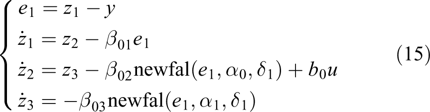
where e
1 is the tracking error, z
1 is the tracking signal of output y,
The function in equation (16) is the core of the entire ADRC design; thus, a reasonable nonlinear function should be designed. The traditional expression of nonlinear functions is as follows

The fal() selected in this study is a new type of nonlinear function. This newfal() has better smoothness, continuity, and derivability near the origin and better high-frequency flutter suppression and self-interference immunity than traditional ADRC. The function expression is as follows

To verify the excellent performance of newfal(), the values

fan(), fal(), and newfal() contrast waveform.
The observation result of ESO on the state variable determines the compensation effect of the system. On the basis of the formulas, the parameters that need to be tuned are ESO gain coefficients
As shown in Figure 7, ESO can observe and compensate for nonlinear dynamics, model uncertainties, and external disturbances contained in the system. As long as ESO converges, the observation error must approach zero. Therefore, the estimated total disturbance is close to the actual total disturbance.
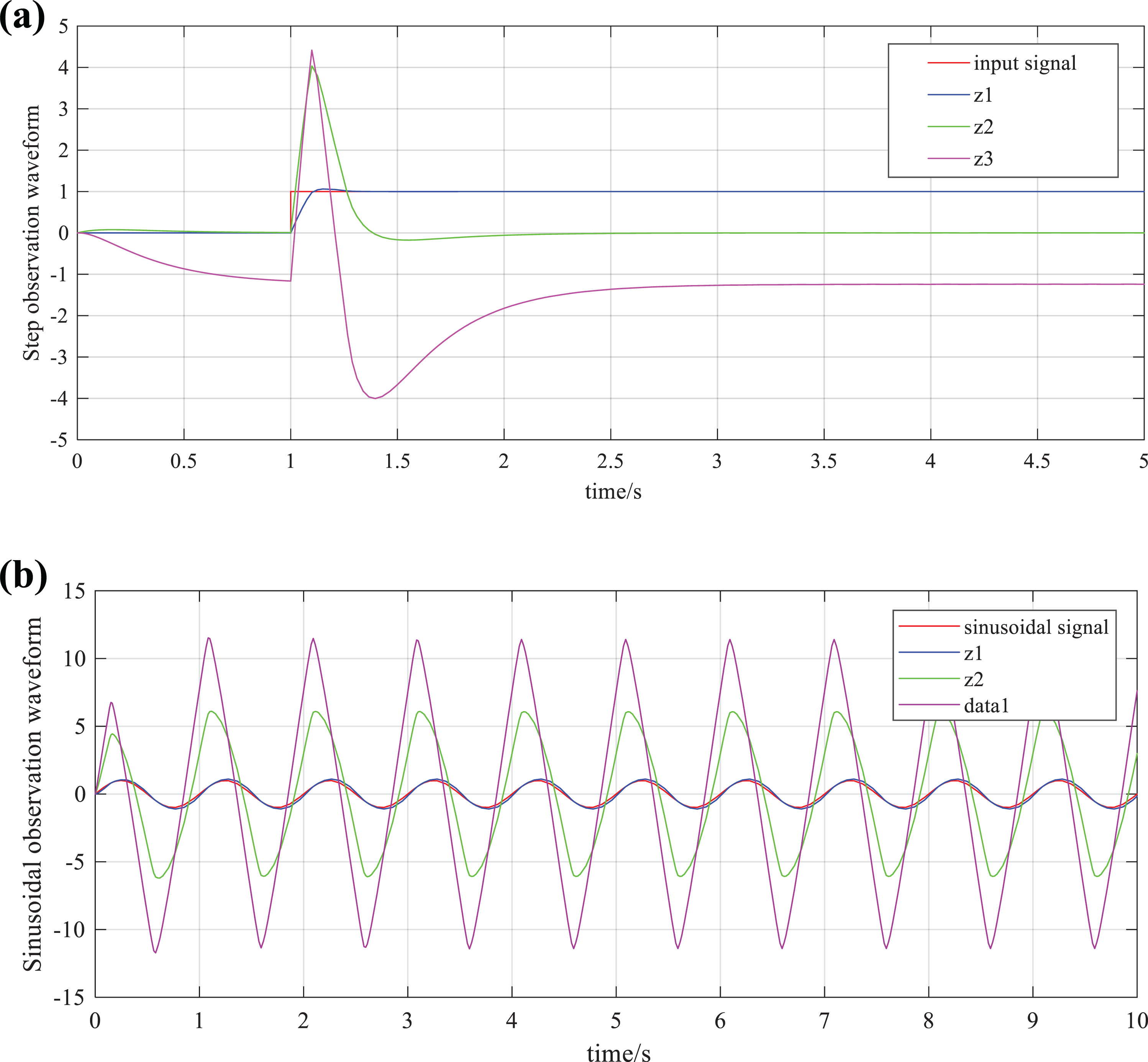
(a) Step input signal response curve. (b) Sinusoidal input signal response curve.
Stability analysis of ESO
The following assumption is to study the convergence of the estimated error system.
Assumption
Any second-order perturbed system can be extended to the third-order linear system is shown in the following equation

When the external disturbance is zero, the error system of ESO is given by subtracting expression (15) of this article from expression (18)

The error system can be further written as

Theorem
If the principal diagonal element of matrix D is positive and the symmetric matrix DG(e) is positive definite, then the zero solution of the system (equation (18)) is Lyapunov asymptotically stable.
Proof
The matrix DG(e) is processed to obtain
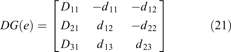
where
If the DG(e) symmetry is positive definite, then the following six conditions must be satisfied
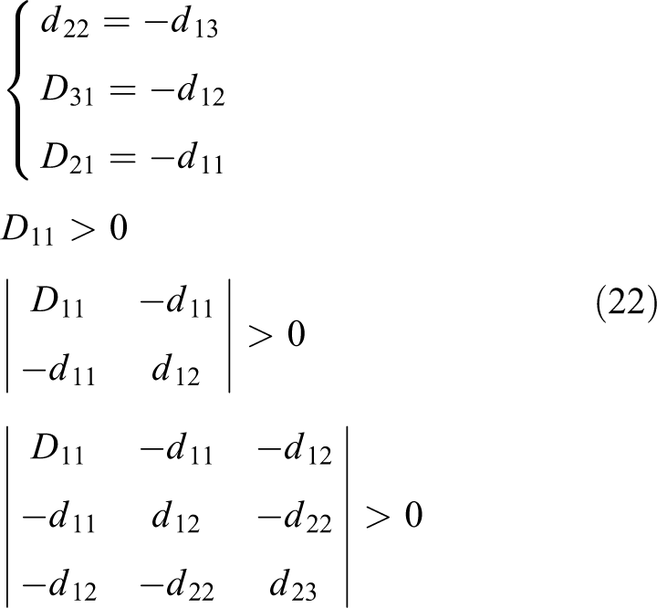
Let

where ε is a positive number that satisfies conditions greater than zero. ε1 and ε2 are values close to zero with respect to ε.
Equation (21) is substituted into the Lyapunov function to obtain

This equation shows that as long as the derivative of the Lyapunov function is less than zero, the Lyapunov function will always decrease and the system will be asymptotically stable. In summary, when
Nonlinear state error feedback
TD generates the transition and differential signals, and ESO obtains the observation estimates of the output. NLSEF can combine their errors in a nonlinear manner. The usage of the newfal() function for constructing nonlinear control law has fast convergence, good robustness and adaptability, and the advantage of “small error and large gain, large error and small gain.” The specific algorithm is as follows

where β1 and β2 are the gain coefficients of the error and the error differential, respectively. α0 and α1 are nonlinear factors, with a number between 0 and 1, and δ2 is the filter factor.
The newfal() function has better convergence, robustness, and smoothness than the previous fal(); it solves the problem of non-smoothness at the inflection point and easily produces jitter, which is suitable for selection.
Disturbance compensation device
After the observation of the system disturbance by ESO, the disturbance must be compensated for. Disturbance compensation does not distinguish between internal and external disturbances, and all disturbances and coupling effects between velocity and tension are regarded as the total disturbance of the system and compensated for. The specific function is as follows

where u is the control quantity of the controlled object, u
0 is the control signal before the disturbance compensation, and
Control system design
Design of Kalman filter
The design of Kalman filter has two main purposes: to estimate the load torque and suppress the influence of noise. As shown in equation (13), we can obtain the following equation

Equation (27) can be simplified as
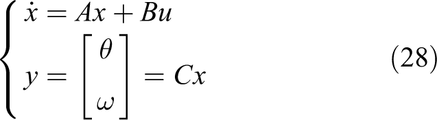
where
Considering the influence of system model and measurement errors, the following can be obtained after the above formula is discretized
where
Suppose the covariance matrix of noise is as follows

Covariance matrix of the estimation errors of state variables at time k is as follows

To summarize, the Kalman observer can be designed with the following steps.
First, the dynamic equation is rewritten as follows

Second, the Kalman observer is initialized as follows
Then, for sampling time

Ultimately, ADRC can be redesigned as

Manipulator joint servo system based on ADRC
On the basis of the established model of the DC torque motor, the ADRC strategy is designed, as shown in Figure 8. All components are selected as previously described.

ADRC structure.
In Figure 8, as the core controller of the entire design system, the ADRC can estimate the total disturbance in time and control the output by compensating for the disturbance; thus, the system has better robustness and rapidity. Kalman filter before ESO can accurately estimate the load torque. Compared with the traditional ESO, the ADRC method can effectively suppress noise and improve the anti-interference ability of the system. Mathematical modeling of joint DC torque motor is helpful for a further comprehensive understanding of the response, speed regulation, and mechanical characteristics of the motor. The smooth transition signal
Simulation experiment
To verify the excellent performance of the proposed ADRC, the control model is established, as shown in Figure 8. Improved ADRC, traditional ADRC, and PID are simulated under the same input conditions. In the simulation experiment, all kinds of restrictions on the actual process are ignored, for example, the actuator will have the constraints of action amplitude and action speed, structural or security constraints. On the basis of the setting principle of ADRC, the parameters are selected, as presented in Table 3.
Traditional/improved ADRC parameters.

ADRC: active disturbance rejection control; TD: tracking differentiator; ESO: extended state observer; NLSEF: nonlinear state error feedback.
Six different step signals are used for simulation experiments. Figure 9 shows the response curves of ADRC and PID. A comparison of the two controls indicates that ADRC has the advantages of fast regulation and no overshoot under step condition.

(a) to (f) Different step signals response comparison waveforms of ADRC and PID. ADRC: active disturbance rejection control; PID: proportion–integration–differentiation.
Figure 10 shows the response curves of ADRC and PID when the input signal is step. PID reaches a stable value after 1.455 s, enters a stable state after 3.508 s, and obtains a 3.15% overshoot. Traditional ADRC reaches a stable value after 1.288 s with 0.85% overshoot and enters a stable state after 2.103 s. On the contrary, improved ADRC enters a stable state after 1.097 s without overshoot. A comparison of the three controls indicates that improved ADRC has the advantages of fast regulation and no overshoot under step condition. When the unit step signal is inputted and 10-rad step disturbance is suddenly added after 5 s, the ADRC and PID controllers are unstable. However, their disturbance amplitude and recovery time are different. PID has a significant jump and is restored to a stable state after 1.906 s. Traditional ADRC has a small fluctuation and the recovery time is 1.101 s. Improved ADRC shows very small fluctuation and minimal disturbance with almost no fluctuation. The anti-interference ability of ADRC considerably exceeds that of PID.
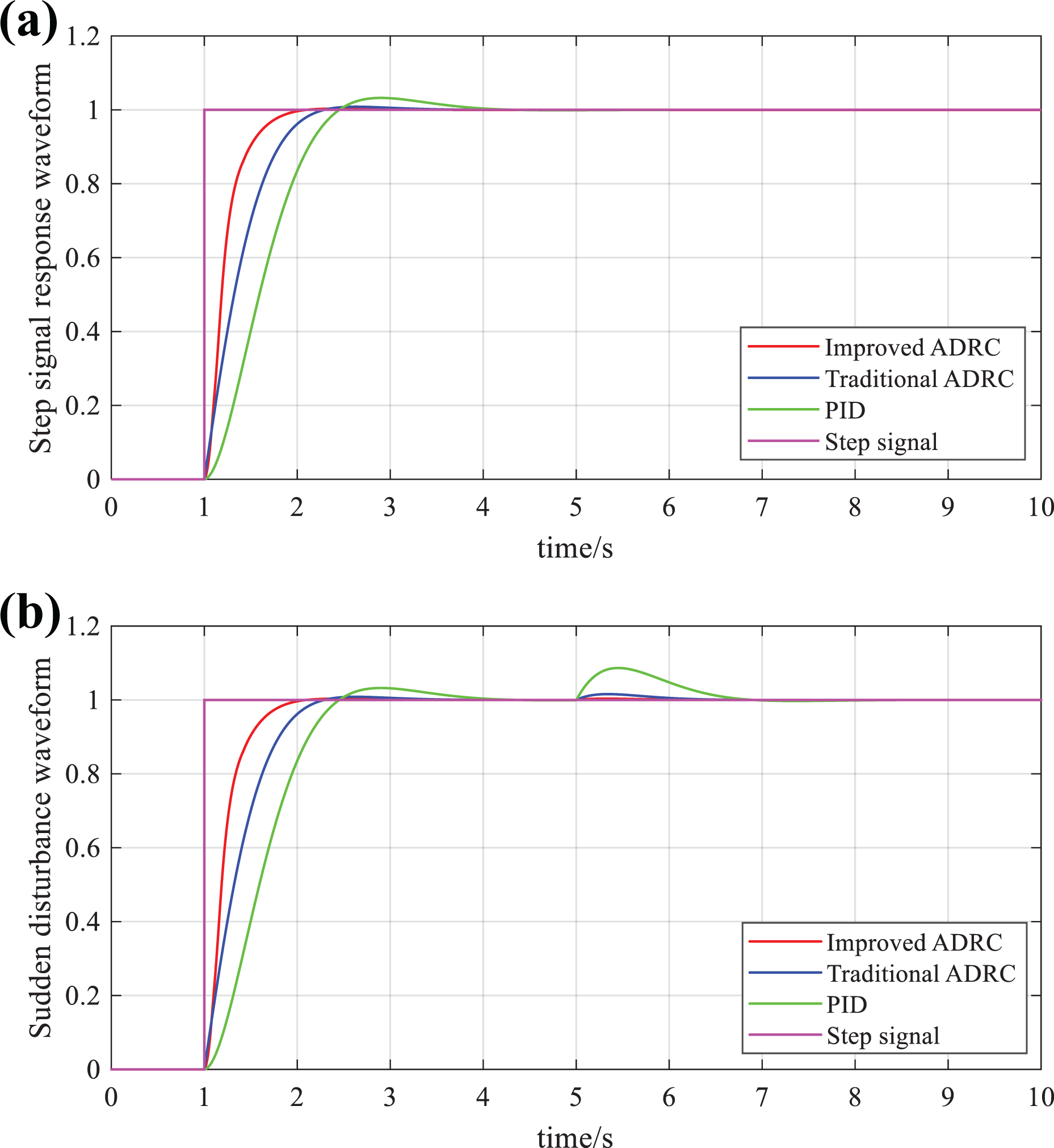
(a) Step signal response waveform comparison. (b) Sudden disturbance signal response waveform comparison.
Figure 11 shows the response curves of ADRC and PID when the input signal is sinusoidal. The figure reveals that the response curve of PID is not smooth, reaching the first peak at 0.752 s with an error of 0.585 rad. Traditional ADRC response curve rises to the first peak after 0.594 s with an error of 0.295 rad. Moreover, improved ADRC response curve is further smooth and stable. The first peak value is reached within 0.551 s after the input signal is added, and the error is only 0.163 rad. After comparison and analysis, improved ADRC is concluded to have faster response speed and fewer errors than PID and traditional ADRC.

(a) Sinusoidal signal response waveform comparison. (b) Tracking error response waveform comparison.
Figure 12 shows the response curves of ADRC and PID when the input signal is square wave. The time for the PID to enter the stable state under square wave signal is 1.445 s with 3.15% overshoot. Traditional ADRC reaches a stable value after 1.288 s with 0.85% overshoot. Furthermore, improved ADRC enters the expected stable state within 1.097 s. When the white noise interference is added, compared with the other two, the improved ADRC has almost no fluctuation. Therefore, improved ADRC has faster recovery time, smaller overshoot, and stronger anti-interference ability. Table 4 presents all characteristic response values.

(a) Square wave response waveform comparison. (b) White noise disturbance response waveform comparison.
Comparison results under different signal inputs.

ADRC: active disturbance rejection control; PID: proportion–integration–differentiation.
The analysis indicates that improved ADRC quickly estimates the disturbance value through ESO and compensates in time to improve the anti-interference ability of the model. The simulation results show that improved ADRC has excellent performance, such as fast response, high control accuracy, no overshoot, and strong robustness, compared with the PID control system.
Conclusion
The control of the six-axis serial manipulator should have good static performance, dynamic quality, and anti-interference ability. In this study, an improved ADRC of the six-axis serial manipulator is designed and implemented. The ADRC has four components: TD, ESO, NLSEF, and DCD. ESO and NLSEF are constructed with a newfal() function. DC torque motor is used as the actuator of the servo system, and the mathematical model of the motor is established on the basis of its four balance equations. To verify the feasibility of the ADRC strategy, the components of ADRC are simulated and analyzed separately, and the optimal parameters of control performance are selected. Meanwhile, the control response curves of improved ADRC, traditional ADRC, and PID are compared and analyzed under the same conditions. The experimental results show that improved ADRC has faster response speed, smaller overshoot, and stronger robustness than traditional ADRC and PID, which proves the performance of the improved ADRC. The improved ADRC control strategy can be used for reference in linkage mechanism research. This research may still be improved to investigate the control effects of ADRC on the manipulator speed.
Footnotes
Declaration of conflicting interests
The author(s) declared no potential conflicts of interest with respect to the research, authorship, and/or publication of this article.
Funding
The author(s) disclosed receipt of the following financial support for the research, authorship, and/or publication of this article: This work was supported by the Anhui Natural Science Foundation (no. 1808085MF182), the Anhui Provincial Key Research and Development Plan Project-Special Scientific and Technological Cooperation with Foreign Countries (no. 1804b06020368), the National Natural Science Foundation of Anhui Polytechnic University (no. Xjky02201906), the Graduate Innovation Project of Anhui Polytechnic University (no. 2019YQ06), and the Anhui Provincial Natural Science Foundation (no. 1808085QE169).