
Abstract
The pitching axis of a satellite camera is controlled under the weightless environment. A novel active disturbance rejection controller is designed to eliminate the influences of the pitching axis. The novel active disturbance rejection controller is designed based on a new nonlinear function, and thus, this function is first established. The function exhibits better continuity and smoothness than previously available functions, hence, it can effectively improve the high-frequency flutter phenomenon. Therefore, the novel active disturbance rejection controller based on the new nonlinear function can eliminate disturbances of the pitching axis. The novel active disturbance rejection controller is composed of a tracking differentiator, a novel extended state observer, and a novel nonlinear state error feedback. The tracking differentiator is used to arrange the transient process. Nonlinear dynamics, model uncertainty, and external disturbances are extended to a new state. The novel extended state observer is utilized to observe this state. The overtime variation of the system can be predicted and compensated using the novel extended state observer. The novel nonlinear state error feedback is adopted to restrain the residual errors of the system. Finally, simulation experiments are performed, and results show that the novel active disturbance rejection controller exhibits better performance than the traditional active disturbance rejection controller.
Keywords
Introduction
The posture of satellite cameras is controlled by three axes. The pitch posture is controlled by the pitching axis, the side swing posture by the side swing axis, and the drift angle by the drift angle adjustment axis. Pitching axis is important for the posture control system of satellite cameras. A three-loop (i.e. current loop, speed loop, and position loop) servo control system is adopted as the control strategy for the pitching axis control system. The speed loop of the pitching axis should be controlled in real time to enable it to achieve good performance. Guan and Zheng 1 and Yang et al. 2 introduced an integrated design method for posture control in satellite cameras. Wang et al. 3 presented an on-orbit calibration approach for satellite cameras based on an iteration method with weights. However, these works did not provide an effective method to eliminate disturbances in the speed-loop control system of satellite cameras. In this study, a novel active disturbance rejection controller (ADRC) is used in the speed-loop control system to enable it to achieve good performance.
The ADRC was introduced by Han.
4
This controller does not depend on the system model, and instead, it is a control method that relies on the errors of the process to eliminate system errors.5,6 The ADRC is composed of a tracking differentiator (TD), an extended state observer (ESO), and a nonlinear state error feedback (NLSEF). The TD is used to arrange the transient process. The ESO is utilized to estimate the total disturbances of the system. The NLSEF is adopted to confine residual errors in the system.7–9 Extensive research on the application of ADRC has been conducted locally and internationally, and several achievements have been reported. For example, Chong et al.
10
and Guo and collegues11–13 designed a fuzzy ADRC and improved the performance of a system. However, the accurate estimation and real-time compensation of the total disturbance were not discussed in detail. Fu et al.,
14
Xia et al.,
15
Sira-Ramírez et al.,
16
and Zhu et al.
17
studied a control system based on ADRC. However, the parameters of ADRCs were too extensive to establish, and thus, they did not provide specific rules for doing so. A novel, unifying concept of disturbance rejector is proposed to compliment the traditional notion of controller.
18
The methodology of ADRC and the progress of its theoretical analysis are reviewed.
19
Wang et al.
20
designed an ESO with a power function filter to effectively estimate the state variables of a system. However, the amount of noise was substantial when the differential was estimated. Wu and Chen
21
and Lin et al.
22
regarded the inertia filtering function as a known part of a system, and thus, the number of parameters that should be set was reduced. Nevertheless, noise was still not eliminated in this system because the power function was used in ADRC. In another study, an ADRC was adopted to analyze the stabilization of nonlinear systems with actuator saturation.
23
Meanwhile, another work applied an ADRC with an adaptive ESO in the air–fuel ratio control of gasoline engines.
24
In addition, the absolute stability of nonlinear ADRC for single-input and single-output (SISO) systems was analyzed using the circle criterion method.
25
Moreover, the trajectory tracking problem of a delta robot was solved through an adaptive ADRC.
26
However, the ADRCs used in the aforementioned works were traditional and designed based on a nonlinear function called
In this study, a novel ADRC is designed based on a new nonlinear function called
Structure chart and model
Structure chart of the pitching axis
The structure chart of the pitching axis is shown in Figure 1. The rotating mechanism is fixed on the satellite using a holder. The satellite camera is fixed on the pitching axis, therefore, the pitching posture control for the pitching axis can be realized. A balance wheel is used to balance the angular momentum caused by the pitching movement. A reducer, a sun gear, and a planet gear are used as transmissions to control the angular velocity of the balance wheel.

Structure chart of the pitching axis.
Permanent magnet synchronous motor models
In this study, a permanent magnet synchronous motor (PMSM) is used as the actuator in the pitching axis control system. Therefore, PMSM models are established in this study. These models include a voltage equation, a flux equation, a torque equation, and a kinematic equation. The following assumptions are made. First, the saturation effects of the iron core are disregarded. Second, the air-gap magnetic field exhibits a normal distribution. Third, the wastage of the eddy current and the magnetic field is disregarded. Fourth, no damper winding exists on the motor rotor. The kinematic equation for the PMSM on the two-phase system (i.e. dq coordinate system) is given as follows
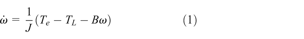
where B is the friction coefficient, J is the rotational inertia of the motor,
Design of novel ADRC
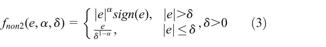
Improvement of nonlinear function
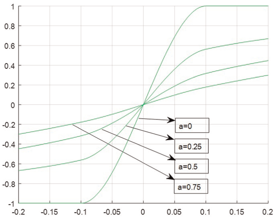
The improvements of nonlinear function follow the succeeding forms based on extensive discussions regarding the simulation. First, the nonlinear function was selected as the

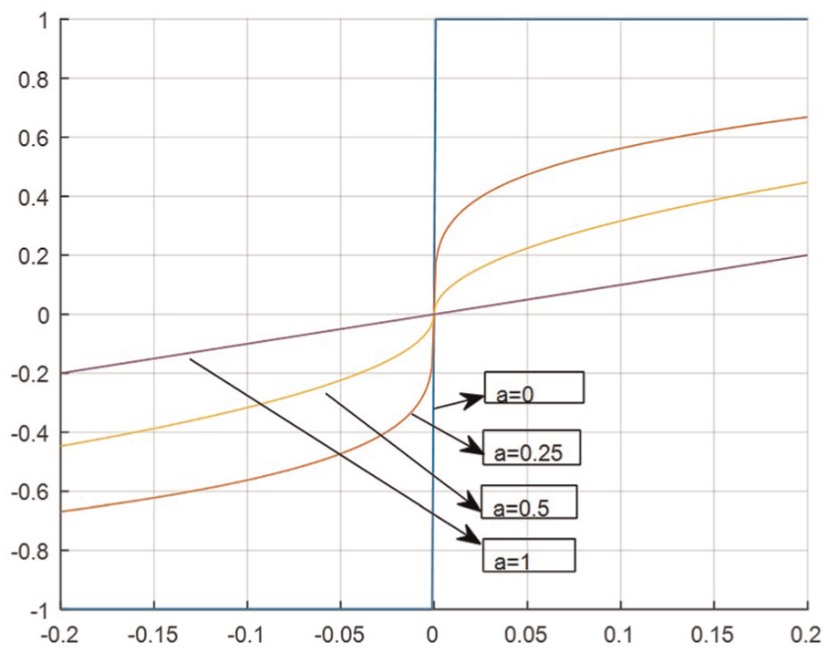
Characteristic curves of
The derivation of function
The characteristics of function

where
When


When


From equations (5)–(8), the following expressions can be derived


Thus, the nonlinear function
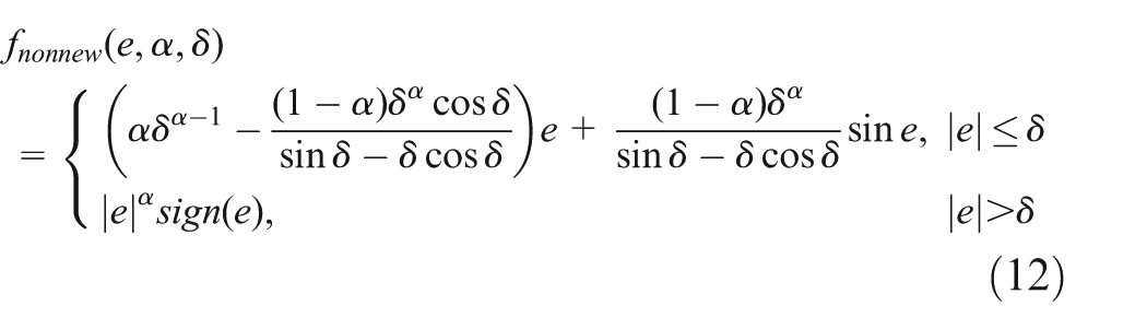
The expression of the nonlinear function

Characteristic curves of
Characteristic curves of
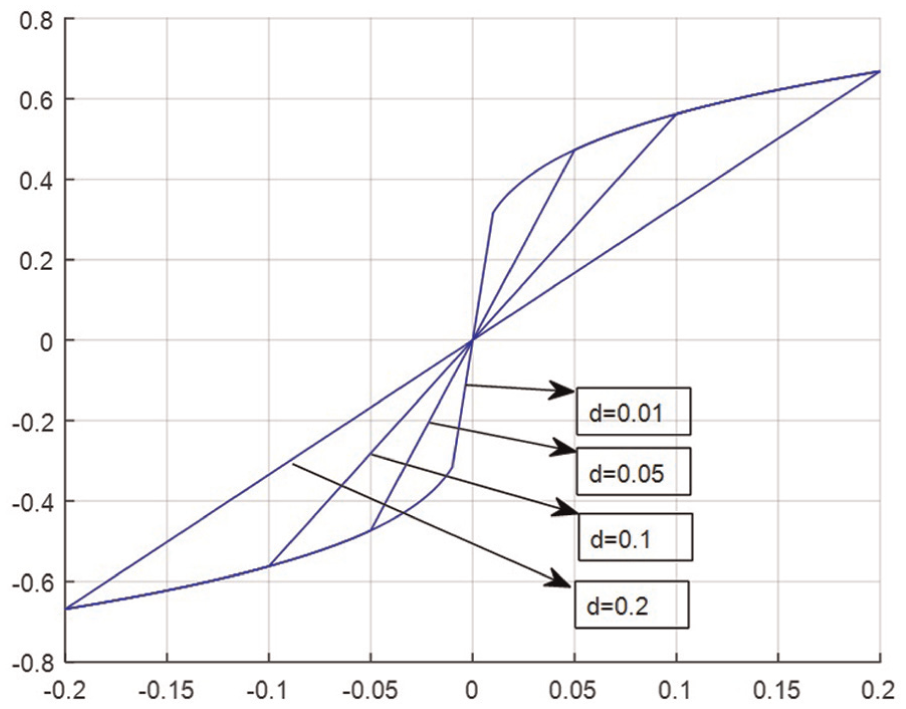
Characteristic curves of

Characteristic curves of

Characteristic curves of
The simulation results demonstrate that the
Novel ADRC design
The key to speed-loop control is controlling the electromagnetic torque. The feedback control can be designed based on the error of the given speed and the speed readings; thus, effective control can be achieved. 29 The control principle diagram of the speed loop based on the novel ADRC is shown in Figure 8.

Control principle diagram of the speed loop based on novel ADRC.
TD
In the novel ADRC, the TD is used to arrange the transient process. A continuous and differentiable input signal can be obtained using the TD. Thus, drastic changes in the control signal can be effectively avoided. The expression of the TD is given as

where

where
Novel ESO
The novel ESO is design based on the new nonlinear function

where
Assume that

Assume that

where

Internal principle diagram of the novel ESO.
Novel NLSEF
The novel NLSEF is adopted to combine the state variables produced by nonlinearly tracking the TD and the ESO with the error of the estimated value. The expression of the novel NLSEF is given as

where
Design of the novel ADRC for a pitching axis
The key to speed-loop control is controlling the electromagnetic torque according to its relationship with the load torque. The feedback control strategy for the speed loop can be designed based on the speed error and the given speed. Therefore, torque control can be effectively achieved. Speed loop is also influenced by uncertain disturbances, such as rotational inertia and load torque. Thus, the main purpose of the speed-loop controller is to eliminate such influences. The disturbances and errors in model linearization are eradicated using the novel ADRC. Hence, the objective of removing uncertain factors is realized. Unknown external disturbances are considered; thus, the input is set to

The novel ADRC of the speed loop can be designed through the following steps. Several definitions are provided as follows

Therefore, the expression of the kinematic equation with extended states can be expressed as follows

Expression of the TD is established as follows

Expression of the novel ESO is established as follows

Expression of the novel NLSEF is established as follows

where
Simulation experiment and discussion
In this section, the novel ADRC is compared with the traditional ADRC to analyze their performances. A PMSM which type is KBM-43X01 was selected as the executing agency of the system. The motor parameters are listed in Table 1. The parameters of the traditional ADRC are provided as follows
Parameters of the experiment motor.

The parameters of the novel ADRC are provided as follows

Simulations are conducted using the traditional ADRC and the novel ADRC in the following cases. First, simulations are performed when the motor starts without a load. A given speed of 100 r/min is applied on the motor at 0 s. Figure 10 shows the speed response curves under the two control strategies. The figure shows that the novel ADRC has a shorter adjustment time and a smaller overshoot amount than the traditional ADRC. The simulation results demonstrate that the overshoot amount of the novel ADRC is 13.098% less than that of the traditional ADRC, and the response time of the novel ADRC is 1.625 s less than that of the traditional ADRC. The parameters of overshoot amount and response time are presented in Table 2.

Speed response curve when the motor starts without a load.
Response parameters of the system when the motor starts without a load.

ADRC: active disturbance rejection controller.
Second, simulations are conducted when an external load disturbance is suddenly applied on the motor. The initial speed of the motor is set to 100 r/min. An external load disturbance of 50 r/min is applied on the motor at 5 s. The speed response curves under the two control strategies are shown in Figure 11. The simulation results demonstrate that the novel ADRC has a smaller response curve fluctuation, a shorter recovery time, and a smaller load disturbance influence than the traditional ADRC. The simulation results show that the overshoot amount of the novel ADRC is 13.068% less than that of the traditional ADRC, and its response time is 1.441 s less than that of the traditional ADRC. The speed-loop response parameters are presented in Table 3.

Speed response curve when an external load disturbance is suddenly applied on the motor.
Response parameters when an external load disturbance is suddenly applied on the motor.
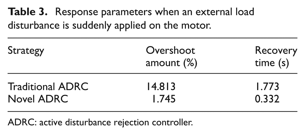
ADRC: active disturbance rejection controller.
The response curves of output y and state variable
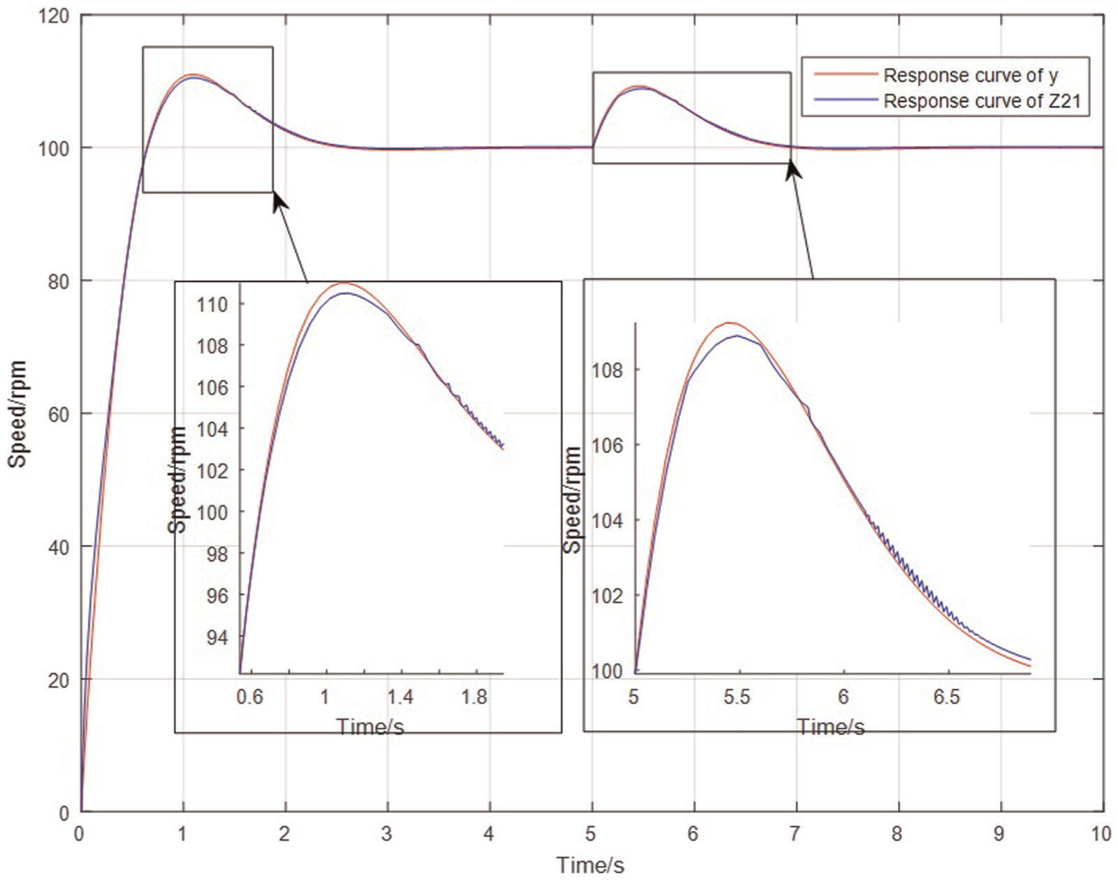
Response curves of y and
The response curves of output y and state variable

Response curves of y and
As shown in Figures 12 and 13, state variables

Response curves of
The response curves of

Response curves of
Figure 14 illustrates that
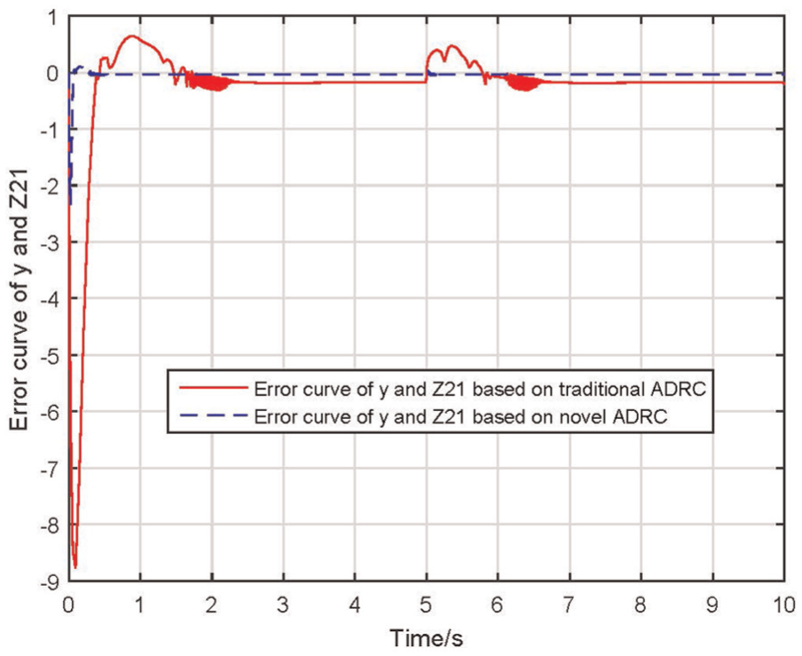
Response curves for the error of y and
The response curves for the error of

Response curves for the error of
Figure 16 indicates that the recovery time of the traditional ADRC for interference is 1.672 s, whereas that of the novel ADRC is 0.097 s. Figure 17 shows that the error of
Third, simulations are conducted when the speed of the motor suddenly changes. The initial motor speed is 100 r/min, which decreases to 50 r/min at 4 s. The speed response curves are shown in Figure 18. The figure indicates that the novel ADRC has smaller response curve fluctuations and better recovery capability than the traditional ADRC. The simulation results demonstrate that the amount of overshoot of the novel ADRC is 8.034% less than that of the traditional ADRC, and its response time is 1.588 s less than that of the traditional ADRC. The speed-loop parameters of overshoot amount and recovery time are presented in Table 4.

Speed response curves when the speed of the motor suddenly changes.
System response parameters when the speed of the motor suddenly changes.
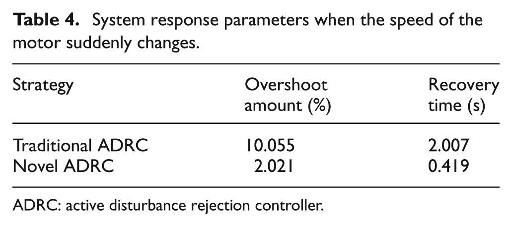
ADRC: active disturbance rejection controller.
A random disturbance signal as measurement noise was applied on the traditional ADRC and novel ADRC. Simulations were carried out and the outputs of ADRCs are shown in Figure 19. Figure 19 shows that the novel ADRC exhibits better elimination capacity for the measurement noise than the traditional ADRC.

Outputs of traditional ADRC and novel ADRC with measurement noise.
Conclusion
In this study, a novel ADRC of the pitching axis speed loop for satellite cameras was introduced based on a new nonlinear function. The non-differentiable and discontinuous characters of the nonlinear function of the NLSEF of the traditional ADRC are addressed using the novel ADRC. The high-frequency flutter phenomenon is reduced significantly.
Simulations are performed when the motor starts without a load, an external load disturbance is suddenly applied on the motor, and the speed of the motor abruptly changes. The simulation results indicate that the system with the novel ADRC exhibits better dynamic performance, static performance, and robustness than the system with the traditional ADRC. The proposed design technique will be extended to the novel ADRC of the current loop and the position loop in our future study.
Footnotes
Academic Editor: Ramoshweu Lebelo
Declaration of conflicting interests
The author(s) declared no potential conflicts of interest with respect to the research, authorship, and/or publication of this article.
Funding
The author(s) disclosed receipt of the following financial support for the research, authorship, and/or publication of this article: This work was supported by Key Project of Natural Science by Education Department of Anhui Province (KJ2015A316), Outstanding Young Talents at Home Visit the School Training Project (gxfxZD2016101), Natural Science Foundation of Anhui Province of China (1508085QE83), and Natural Science Foundation of China (51605464).