
Abstract
In robotics, the tough problem about the dynamic target capturing consists of tracking the target by the robot manipulator and grasping the target by the robot finger. For the sake of space, this article deals with only the first problem, tracking the dynamic target by the robot manipulator. The traditional approaches of capturing the dynamic target may work well when they are employed in low-dimensional space by reinforcement learning or physical modeling. However, they fail to work well in high-dimensional space. The traditional approaches have four limitations with respect to Cartesian space, configuration space, reinforcement learning, and physical modeling. To overcome these limitations, this article implements improved dynamic A* algorithm in high-dimensional configuration space map to capture the target. First, a space injection model injects the collision detection and target position from the Cartesian space into the configuration space to construct a high-dimensional map. Then, the target capturing method including the improved dynamic A* algorithm is applied on the map to track and capture the target. Finally, the experiment performed in time-varying environment and the dynamic target achieves a reliable result. This article has proposed an approach that makes the robot manipulator motion planning more accurate in high-dimensional dynamic configuration space. This approach enables the multi-joint manipulator to avoid the obstacle while tracking the target in high-dimensional configuration space. It takes the advantages of heuristic algorithms in the process of target capturing method designing. It adds precision and speed to target tracking. The success of the approach may apply to any industrial robot tracking target, surgical operation, and space probes. And, it may lay a solid foundation for dynamics control with a scope for future investigations.
Keywords
Introduction
The task of capturing a dynamic target requires that the manipulator should not only grasp the specified target by the robot finger, but also track the dynamic target by the robot manipulator. Tracking the target by the robot manipulator is more complex and difficult because the target is not always stationary. And the greater of space’s dimension, the greater number of joint angular motions to reason about, and the more choices in selecting the capturing methods. 1
The traditional studies have researched this problem in four directions, and each of the four directions has its limitations. The first direction is capturing the dynamic target in the Cartesian space. The Cartesian space is more suitable for presenting the Euclidean distance, which optimizes a physical three-dimensional Cartesian space-related criterion of speed and dynamics control. And it is more useful in collision detection because the working environment of the robot is very complicated with various obstacles in static or moving status. That is the reason why the Cartesian space 2 proves to be an easier way than the configuration space in physical feasible motion planning for capturing the dynamic target. 3 The second direction is capturing the dynamic target in the configuration space. The motion of the manipulator’s actuator is generated in the configuration space, which presents the arm trajectory, elbow trajectory, and wrist trajectory directly without the application of the inverse kinematics. The limitations of the Cartesian space and the configuration space are that tracking trajectory on the operational level is formulated in the configuration space, whereas the physical motion law of tracking trajectory is defined in the Cartesian space. 4,5 The injection between the Cartesian space and the configuration space is needed so that the tracking trajectory on the operational level and physical motion law of the tracking trajectory can be observed simultaneously. The third direction is capturing the dynamic target by reinforcement learning based on behavior examples. 6 The reinforcement learning is so dependent on training examples that the acquisition of bad generalization and robustness becomes problems. The fourth direction is physical modeling primarily based on the use of mechanism and dynamics. 7 By combining the pseudo-rigid-body-model method, the assumed mode method, and the Lagrange equation, the overall dynamic model is derived. Then, the issue of capturing the dynamic target is solved by numerical simulations of physical motion planning, the velocity model, 8,9 and the prediction of the manipulator’s motion. 10 Although capturing the dynamic target by physical modeling is robust and accurate all the time, physical modeling is fragile with uncertain parameters of the model. Therefore, physical modeling is feasible for only the systems with simple dynamics.
The limitations of these previous methodologies call for a more practical and reliable way. The traditional A*, which is a good heuristic algorithm that works well with capturing the dynamic target in low-dimensional configuration space, might be the solution for limitations in reinforcement learning and physical modeling. 11 But the traditional A* algorithm has hardly ever been applied in areas of capturing the dynamic target by the robot manipulator in high-dimensional configuration space and dynamic environment, and it cannot make up the limitations in the first two directions of the previous studies. First, the traditional A* algorithm cannot capture the dynamic target in the Cartesian space because the tracking trajectory generated in the Cartesian space cannot control the actuator of the robot manipulator directly. Second, the traditional A* algorithm cannot capture the dynamic target in the configuration space because the high-dimensional dynamic configuration space presenting an irregular data access pattern space requires a huge amount of memory, which is often beyond the limits of computing power. 12 To tackle the first limitation, we will use a space injection model that will inject the target position and the collision position from the Cartesian space into the configuration space to generate angular trajectory of actuator in high-dimensional configuration map. As for the second limitation, we will improve the traditional A* algorithm by designating the A* a searching region in a certain sliding hypercube to save computing power. Besides, the space injection model and improved dynamic A* algorithm can be applied to any degree of freedom (DOF) of a robot manipulator, which will enlarge the application range compared with the traditional method. 13
This article is organized into six sections. The first section gives an introduction to the whole article. In the second section, the space injection algorithm between the Cartesian space and the configuration space is formulated. The third section describes the mathematical model of the high-dimensional configuration map. With the space injection model in the second section and the Gilbert–Johnson–Keerthi method, the high-dimensional configuration map divided by cells of collision and collision-free are defined. It brings high accuracy to target tracking and trajectory planning. In the fourth section, based on the principle of heuristic dynamic A* algorithm, an innovative method of capturing dynamic targets in high-dimensional configuration space adapts to the complex environment with continuous updating configuration map to capture the dynamic target. This target capturing method plans the path of the robot manipulator in each cycle of local planning. And the convergence condition of the target tracking algorithm is given. In the fifth section, simulation and experimental results are presented. The results show that the algorithm guides the robot to avoid dynamic obstacles, tracks the dynamic target, and improves searching efficiency. Finally, the sixth section concludes the article.
Space injection model of the robot manipulator
Most of the previous studies of injecting the target and obstacle from the Cartesian space into the configuration space were based on analytical solution of 6-DOF robot manipulator. 14,15 Cases of other-DOF are seldom studied. Therefore, this article will provide a space injection model to study a 5-DOF robot manipulator. And this model can also be applied in other-DOF robot manipulators. The model is built on the specific configuration Denavit–Hartenberg (D–H) coordinate system. And the specific configuration D–H coordinate system and parameters are shown in Figure 1 and Table 1.
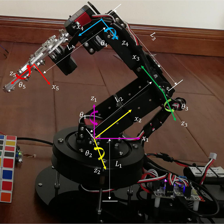
Kinematic scheme of 5-DOF manipulator.
D–H parameters of the 5-DOF manipulator in Figure 1.

D–H: Denavit–Hartenberg; DOF: degree of freedom.
In the injection model, Jacobian equation

since the revolute joint provides an angular motion to a link with its previous one. Angular velocity

For a robot manipulator with 5-DOF, J is non-square; thus an ordinary inverse is not possible. We can try using the pseudo-inverse


Lagrange multiplier is used to convert this constrained optimization equations (2) and (3) into

Taking derivatives with respect to

It is not difficult to verify
The construction of the high-dimensional configuration space map
The traditional method of map construction in Cartesian space is dividing the surrounding area of the robot into a free motion space and a restricted collision space. However, the traditional map constructing method concerning constructing marks and grids does not work in constructing high-dimensional configuration space.
16
To construct the high-dimensional space map, two methods are needed: the Gilbert–Johnson–Keerthi collision detection method and the dynamic map method. The Gilbert–Johnson–Keerthi method is able to quickly detect the collision. And the dynamic map method in the high-dimensional space of the manipulator is meant to speed up the computation,
17
because the configuration map contains a large number of obstacles and manipulator’s pose information. If all the local information is added to the map at one time, it will result in inefficient calculation and introduce more noises. Since the pose of the manipulator and the obstacles on the configuration map do not change much in a very short time, the dynamic map method filters the environmental information by setting up a scan time interval
In the uniformly rasterized configuration space, the construction of the configuration map is based on the space occupation of the manipulator and the obstacle and the collision situation. 16
The process of generating a high-dimensional configuration map is as follows: 1. Defining configuration space boundary
According to the maximum values of

where the maximum values of 2. Meshing the configuration space
According to the accuracy requirement, the side lengths of the boundary in one-dimensional direction are respectively divided into uniform m, n, o, p, q line segments in step. Steps m, n, o, p, q are as follows

where the ceil function regulates 3. Searching for configuration space sub-cell
A searching loop of five-dimensional configuration space constructed in a specific step size iterates the configuration space cell. And in the loop, the collision detection is carried out that discovers the configuration space cell of the robot manipulator without collision, which ensures that the robot manipulator does not fall in the collision area. The collision detection is implemented in a three-dimensional Cartesian space by means of Gilbert–Johnson–Keerthi method. First, the robot manipulator is disassembled into four cubic rods. Cubic rods are meshed to be detected by Gilbert–Johnson–Keerthi method. Second, the Gilbert–Johnson–Keerthi method determines the minimum distance between two convex sets by which it detects whether two convex shapes are penetrating or not. The minimum distance is gained by inputting convex shapes. The input convex shapes must have fields for the Cartesian coordinates of the vertices which are the same as the meshing object. Substitution of the joint angle with the D–H forward equation (DH function) yields the Cartesian coordinates of the collision area to inject the collision detection from Cartesian space to configuration space, as shown in Figure 2. Therefore, searching for configuration space sub-cell is carried out through rapid response of Gilbert–Johnson–Keerthi method.

In Gilbert–Johnson–Keerthi algorithm, the manipulator is decomposed into cubic rods and meshed into convex shapes. Rods of different colors represent different parts of the robot manipulator.
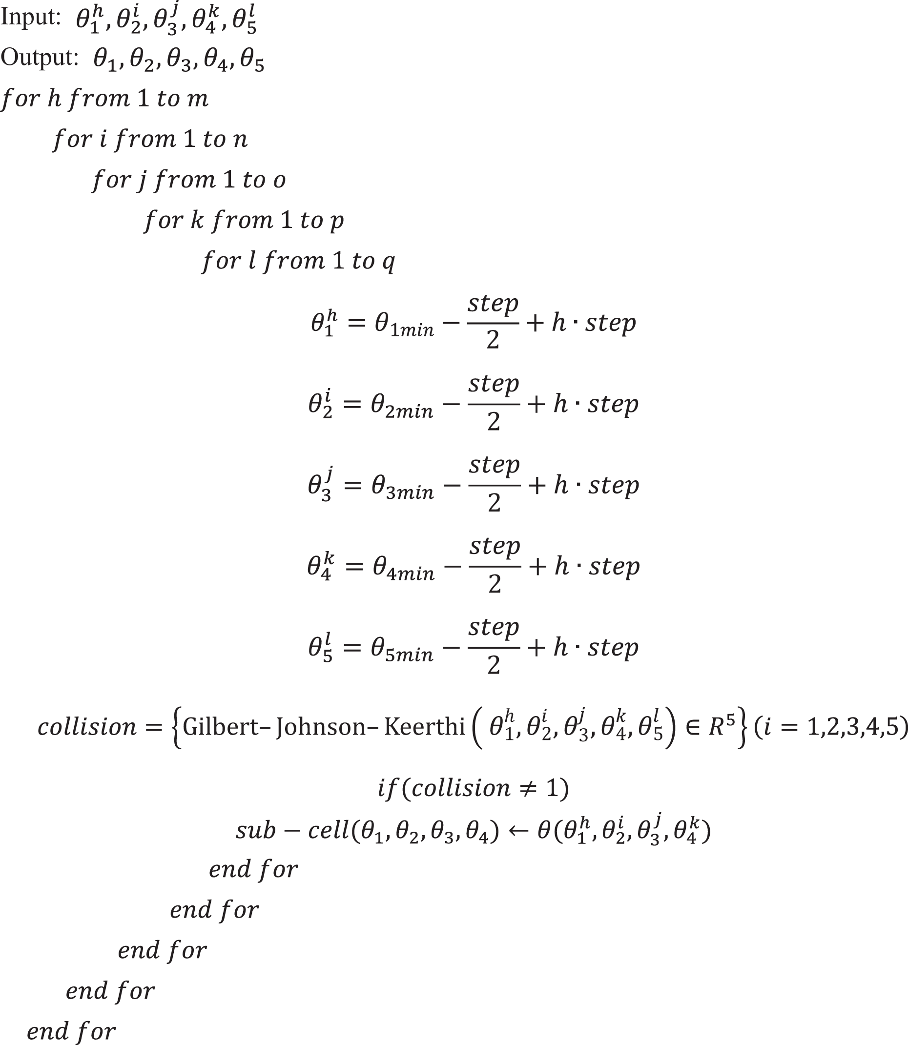
Finally, the cells without collision are marked as the reachable cell. The pseudo-code is shown as follows:
As it is difficult to understand the high-dimensional space, we change a five-dimensional configuration space map into a two-dimensional space yielding 10 low-dimensional maps as in Figure 3. It can be seen from Figure 3 that the information in the high-dimensional space is very complicated. Different colors in the figure represent Euclidean distance from the current cell to the origin cell (cell in the white color) in the Cartesian space. The Euclidean distance is defined as


Hypercube of the configuration space map is mapped into two-dimensional space. The white cell in the center of the two-dimensional projection stands for the original cell. And the color determined by jet color graph array represents the distance from original node to current node.
The color range of each sub-cell in five-dimensional configuration space is determined by jet color graph array. Cells in warm color tones represent high value of distance between this current cell to original white cell. Conversely, cells in cold warm tones stand for low value.
The target capturing method
As it is known, target tracking is essential to target capturing in configuration space map. The construction of configuration map has been solved in the third section, and the problem to be solved in this section is target tracking, which can be resolved by the improved dynamic A* algorithm. The working principle of the improved dynamic A* algorithm and other associated algorithms in Cartesian space and configuration space are presented in Figure 4.

Both collision detection and target state prediction are implemented in three-dimensional space and finally the calculation results are injected into configuration space. The whole process in this picture forms the target capturing method.
As shown in Figure 4, if the traditional A* algorithm is directly used in Cartesian space, the inverse kinematics solution equation (inverse D–H equation) must be called multiple times, which will result in a large amount of search data or even in an infinite search loop. Aiming at the dynamic target tracking problem of the robot manipulator, a heuristic collision-free planning algorithm (the improved dynamic A* algorithm) is proposed based on the configuration space map, so that the robot manipulator can achieve better dynamic target tracking in any pose.
The target state prediction method in the configuration space map
A suitable target motion model helps to accurately predict the future state or motion trajectory of the tracked target, which is an important condition for achieving accurate tracking control. The velocity model of the target motion is often used to predict the state of the system. 19 In the study of target tracking, the target motion model is mainly represented by a state space

where XT
is the target position in Cartesian space;
So the position, velocity vector description, and motion state of the target in three-dimensional Cartesian space are as follows

To track the target in configuration space map, target position prediction method interpreted in the motion state of the robot manipulator is required. To convert prediction model into the configuration space map, decomposition rate motion with


where

The improved dynamic A* motion planning algorithm
When the state of target changes, the target tracking algorithm must adapt with the changes of the target. As a core part of target tracking algorithm, A* algorithm must take the state prediction results from equation (9) described in “The target state prediction method in the configuration space map” section, along with high-dimensional dynamic configuration map described in the third section into consideration, which is insoluble to traditional A* algorithm. To save space and time of computation, improved dynamic A* algorithm assigns the computation of A* nodes sophisticatedly to computing process and it extends nodes in a certain local space of hypercube (see Figure 3) around the current node in high-dimensional configuration space map. In the improved dynamic A* algorithm, the configuration space map is dynamically scanned in the

Another key part in the improved dynamic A* algorithm is evaluation of the manipulator’s 10 actions. The evaluation function

where


The improved dynamic A* algorithm will select the node with the smallest value of

The flow chart of improved dynamic A* algorithm shows the process of planning the trajectory of the joint angle state in the configuration space map.
The target tracking algorithm
To track the dynamic target more accurately in the configuration space map, the pseudo-inverse form of the Jacobian matrix in equation (5), and the target state prediction model defined in equation (9)


where


The theoretical analysis on convergence is given by equations(17) and (18). The error between the state of the manipulator and the state of the target consists of error1 (error of joint angular motion) and error2 (error of joint angular velocity). Equation (17) (error1) and equation (18)

The control block diagram of the target tracking algorithm by applying improved dynamic A* algorithm in the loop. Planned state subtracting the current state yields the joint angular velocity.
Target tracking algorithm handles random collision information while making full use of known environmental information to generate optimal paths. When this target tracking algorithm converges, the dynamic target is captured by robot manipulator.
An illustrative example
The previous chapter has introduced the modeling details regarding to the kinematics of a robot manipulator and target tracking algorithm. In this section, to illustrate the effectiveness of the proposed target tracking algorithm as well as the configuration space map model, an illustrative experiment on the angular motion of robot manipulators is conducted. The experiment is performed based on a 5-DOF robot manipulator with five revolutionary joints, which connect four links in series with the last one being an end-effector.
In this case, the experimental task is the tracking and capturing of a dynamic target by the robot manipulator. If the algorithm manages to track and capture the target with high accuracy, the validity of the method proposed in this article can be proved. The implementation of the algorithm in Simulink is shown below.
Taking time-varying state of the dynamic target in the configuration map into consideration, the Simulink uses discrete computation and memory technologies to guarantee the convergence of robot manipulator’s state to prediction state of the target in configuration space map, which is shown in Figure 7.

The Simulink chart of the target tracking algorithm is corresponding to the control block diagram of the target tracking algorithm.
Each block in Figure 7 plays a different role in this Simulink chart. The velocity block regarding function
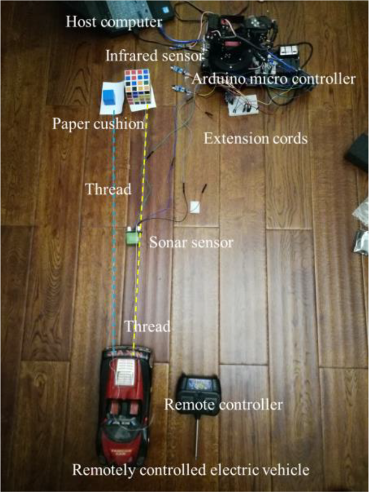
Experimental setup for capturing the dynamic target by the manipulator.
Three parallel infrared sensors are placed on the floor to detect the movement of the obstacle. A sonar sensor is placed on the trajectory of the blue target cube, and the position of the blue target cube is tracked by using sonar-based techniques. A remotely controlled electric vehicle controlled by a remote controller provides the driving force to drag the target cube or obstacle (Rubik’s 4th dimension cube). The signals of the infrared sensor, the sonar sensor, and the robot manipulator are collected by Arduino microcontroller and controlled in real time by MATLAB R16B control system in the host computer. This experimental setup is used to determine the performance including the response and the accuracy of capturing the dynamic target by the manipulator.
In this case, the target and the obstacle are both time-varying. In the time-varying experiment, the target tracking algorithm returning the estimated manipulator state in the configuration space map attempts to get close to the target state. The state of the target in the configuration space map corresponding to the target position in Cartesian space can be predicted by the target state prediction method in “The target state prediction method in the configuration space map” section.
Figure 9 shows the computation process of capturing the dynamic target by the robot manipulator in host computer. The measured data from infrared sensors and sonar sensor must be transmitted via Arduino microcontroller to host computer at a scan time interval less than 4 ms, because the dynamic target capturing experiment is programmed to update at a scan time interval of 4 ms to adapt to the changes of the obstacle and the target. Figure 9 gives a whole picture of the experiment. In the experiment, the prediction state of the target that can be seen in Figure 10 is depicted by joint angles
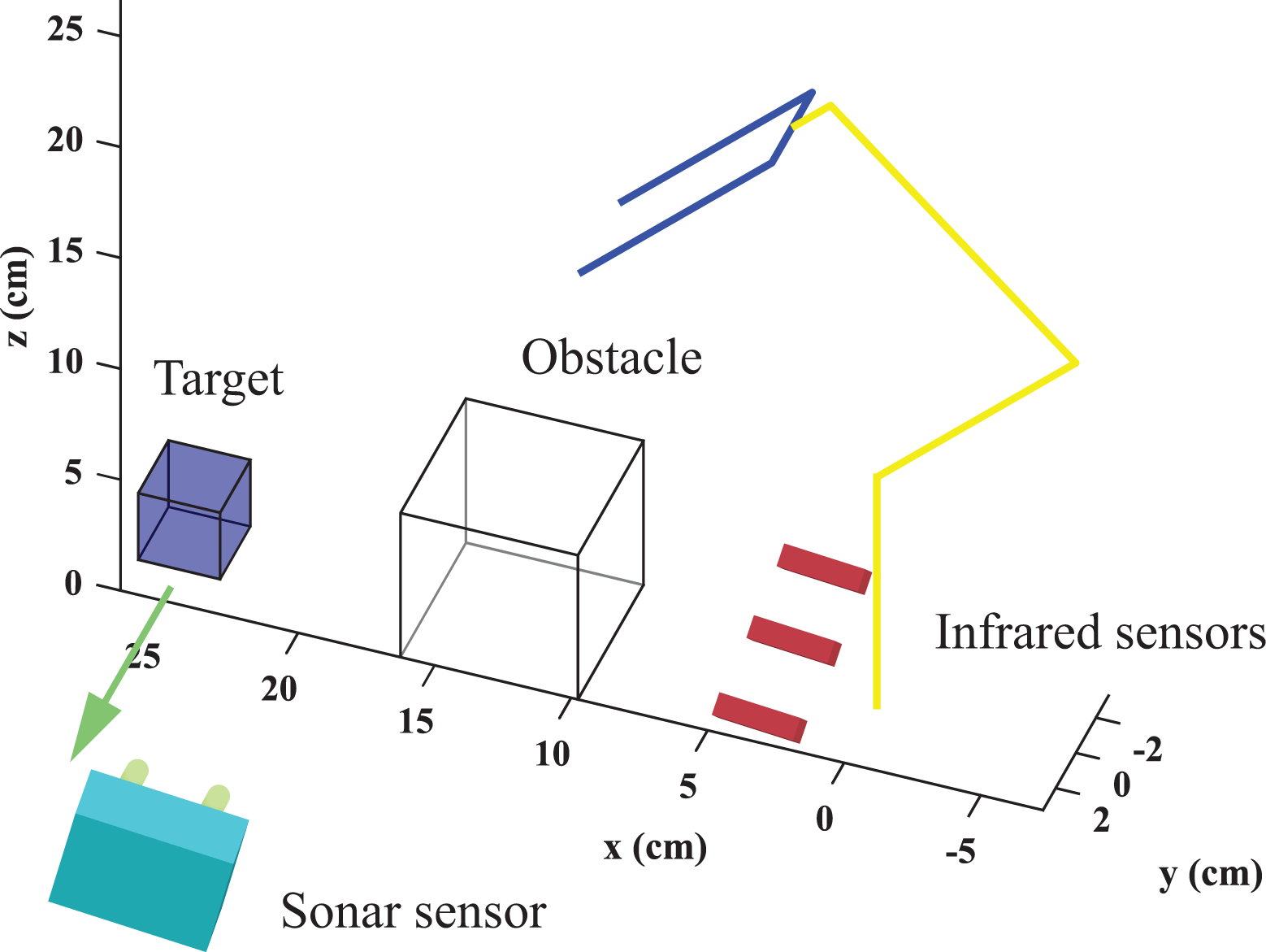
The obstacle represented by the white cube is moving in the direction of the green arrow from the starting point. The blue cube represents the dynamic target.

The state of the target in the configuration space map.
The results shown from Figures 11 to 15 reveal the performance of the target capturing method.
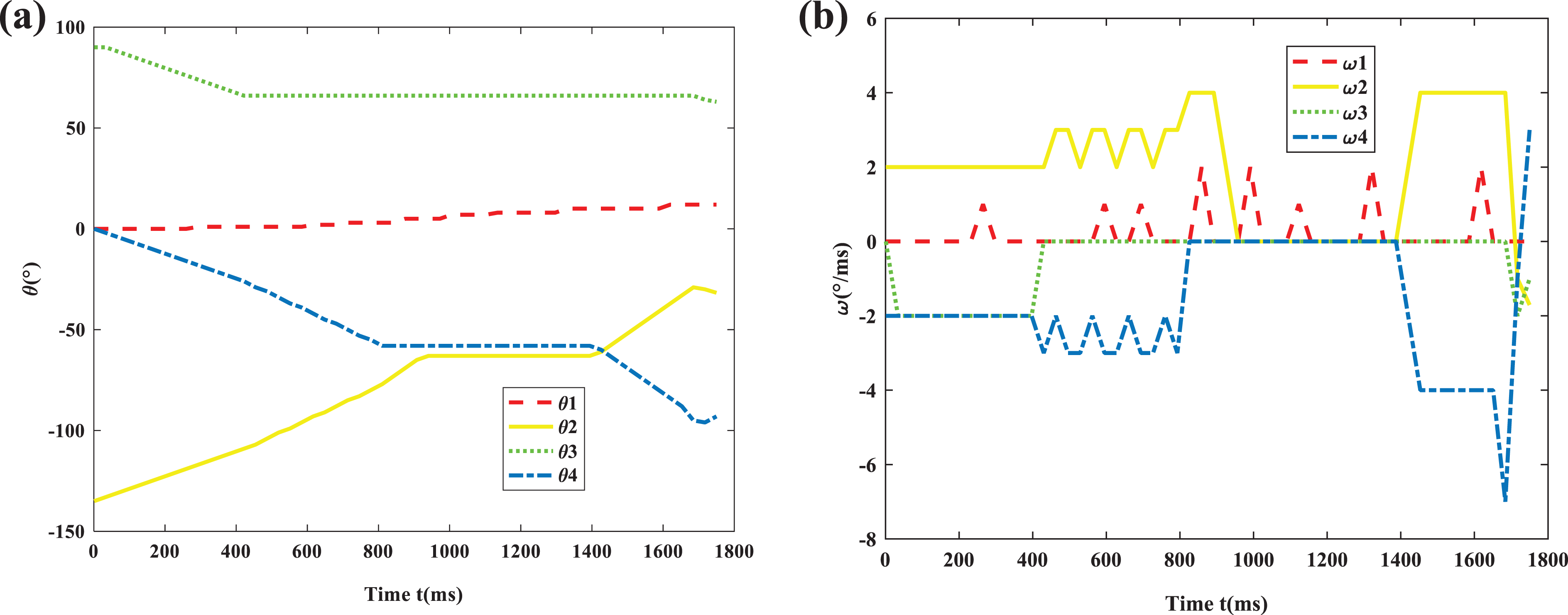
(a) The joint angular motion and (b) the joint angular velocity of the robot manipulator in the dynamic configuration space map and dynamic target, where ω in (b) is equal to

The trajectory of robot manipulator’s end-effector when robot manipulator captures the dynamic target in Cartesian space.

The trajectory of the robot manipulator when robot manipulator captures the dynamic target in Cartesian space.
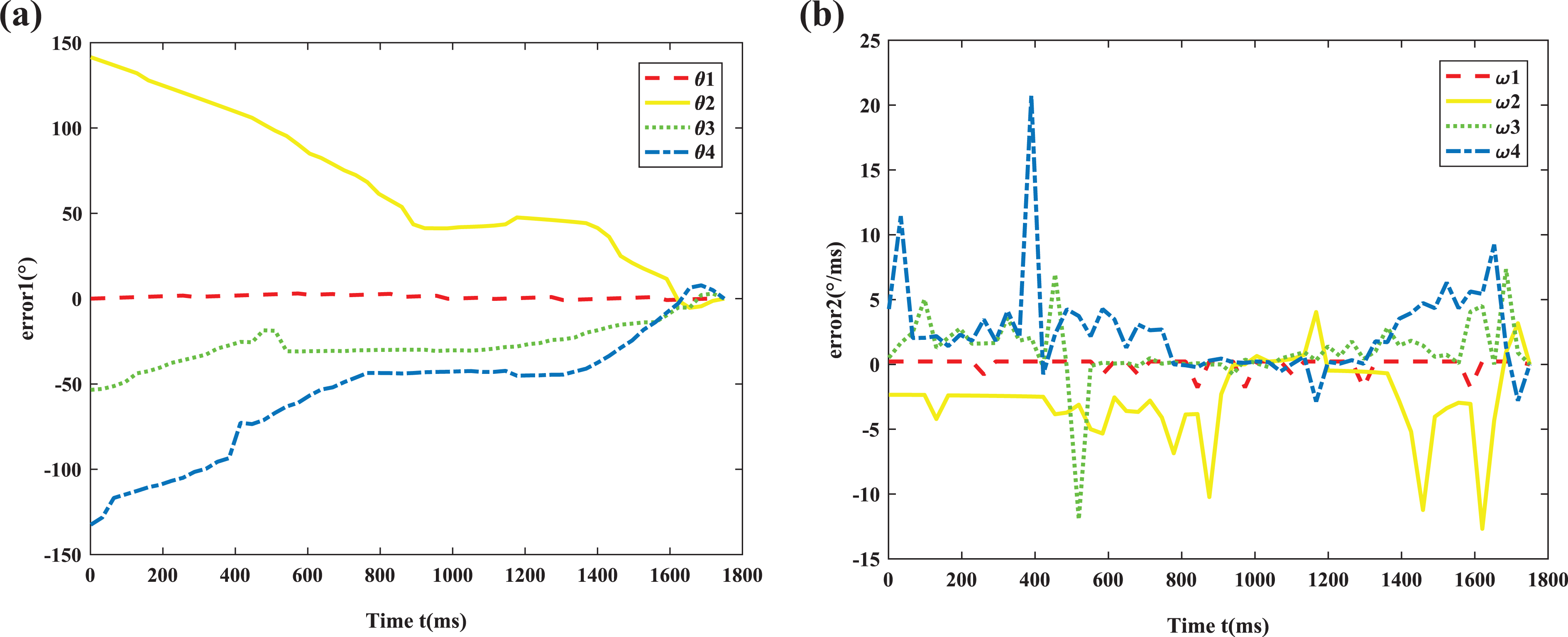
The error curve of the dynamic target capturing method in high dimensional space. (a) Error1 of the joint angular motion. (b) Error2 of the joint angular velocity.

(a and b) In the experiment of capturing the dynamic target by robot manipulator in high dimensional space, the remotely controlled electric vehicle drags the blue cube or the Rubik’s 4th dimension cube by the flat base attached to the thread.
The experiment results shown in Figure 11(a) have been obtained under very dynamic conditions. Each actuator of the robot manipulator aiming at the tracking dynamic target state coordinates so well that the curve of the joint angular motion changes slightly with time. This can also be observed from Figure 11(b), where the desired joint angular velocity for the robot manipulator is shown. This picture also shows the good performance of the proposed dynamic target capturing method with only a small fluctuation of the curve in certain ranges.
The curve in Figure 12 is tracking trajectory of the end-effector in Cartesian space corresponding to joint angular motion trajectory in Figure 12, with the robot manipulator starting from the initial joint angle state (0,−135,92,0) in configuration space and position (29.39,6.24,6.41) in Cartesian space. The robot manipulator is expected to move forward to track the target with the configuration state ending with the joint angle state (12,−38,63,−90) in configuration space and position (2.40,0.29,19.44) in Cartesian space.
In summary, Figures 11 and 12 prove that the dynamic target tracking algorithm plays an important role in the trajectory planning of robot manipulators. The results illustrated in Figure 11(a) and (b) prove that the algorithm has performed at stable speed with maximum 1°/ms in
The optimal trajectory of the manipulator when the dynamic target and the obstacle are moving is shown in Figure 13, where two blue cubes and two white cubes represent the different states of the dynamic target and obstacle, respectively. From the picture, it can be seen that the robot manipulator is trying to capture the target while adapting to the change of the target’s position and the obstacle’s position under the guidance of target tracking algorithm.
Figure 14 shows the error’s value as well as the required convergence time related to the efficiency of the target capturing method. From the picture, it can be seen that error1 and error2 converge around 0. The error convergence may be related to three factors. The first one is the construction of the high-dimensional configuration space map. It delays the target tracking algorithm a bit while, but enables the target tracking algorithm greatly minimize error1 which has been accumulated before 600 ms (see Figure 14(a)). The second factor is planning mechanism of improved A* algorithm. It coordinates the motion of the robot manipulator and stabilizes each robot manipulator’s joint angular velocity (see Figure 14(b)). The third one is the target tracking algorithm which ensures the error curve converging with values around 0. To sum up, the three factors keep the target capturing method effective.
Figure 15 shows one of the experimental results. Figure 15(a) shows the detection phase at which the robot manipulator detects the obstacle (Rubik’s 4th dimension cube) by the infrared sensor. Figure 15(b) depicts the sonar sensor which transfers the signal of the dynamic target’s (the blue cube) movement into voltage signal, which triggers the capturing process. The manipulator has grasped the target successfully. After 10 times experiment of the type just described in Figure 16, the response speed of the target tracking algorithm is obtained.

Response speed of the target tracking algorithm.
Based on multiple experimental results, the response speed of the target tracking algorithm is shown in Figure 16. It shows the shaded region (represents ±1 SD) of the response speed has slightly shrunken by time. And the response speed remained steady at about 35 ms.
Conclusion
In this article, we have presented a new target capturing method in a five-dimensional configuration space map to solve the four vital limitations in traditional studies. Although the two of the limitations can be overcome by the traditional A* algorithm, limitations of the methods in the Cartesian space and the configuration space cannot be resolved by the traditional A* algorithm. Aiming at resolving them, a space injection model has been built to inject the collision position and the target position from the Cartesian space into the configuration space. With the help of the space injection model, a high-dimensional configuration space has been built. Then, the traditional A* algorithm has been improved by a sliding hypercube searching region and the improved evaluation function. Finally, the improved dynamic A* algorithm is used in the constructed high-dimensional configuration space map in the process of dynamic target capturing method. The dynamic target capturing method correlates the state of the target with the state of the robot manipulator, thus ensuring the accuracy of robot motion and target tracking. So far, the four main limitations of the traditional studies on capturing dynamic target by robot manipulator are resolved by the proposed method. The accuracy and practicability of the algorithm are verified from physical experiments. The results of the joint angular motion and the trajectory show that the target capturing method with fewer computations works well in real-time and only sacrifices a little space efficiency. The error analysis results show that the proposed method has good continuity. In summary, the experimental results prove the effectiveness and practicability of the target capturing method in capturing dynamic target by robot manipulator in high-dimensional configuration space map. This method lays a foundation for solving more complex robotic tracking problems. Also, it broadens the application range of the traditional heuristic algorithm so that it can be applied to practical tasks such as dynamic target capturing and dynamic detection by robots in dynamic environments. This core technology is applicable to all kinds of manipulators and different application areas: dynamic target grabbing, assembly line operating, obstacle avoidance in space probe, or surgical operation, for example.
Footnotes
Declaration of conflicting interests
The author(s) declared no potential conflicts of interest with respect to the research, authorship, and/or publication of this article.
Funding
The author(s) disclosed receipt of the following financial support for the research, authorship, and/or publication of this article: This work is supported primarily by the National Key R&D Program of China with grant no. 2017YFC0806300 and the National Key R&D Program of China with grant no. 2017YFC0806608.