
Abstract
Applying snake-like robots to environmental exploration has been a hot topic for years. How to achieve free navigation for target search in a complex environment in a safe and efficient manner is one of the main tasks that researchers in the field of robotics currently face. This article presents a target exploration system that takes advantages of visual sensing to navigate the snake-like robot in structured environments. Two cameras are utilized in the system. The first one is mounted on the head of the snake-like robot for target recognition and the other is an overhead camera which is responsible for locating the robot and identifying surrounding obstacles. All dead ends in the environment can thus be recognized using a template-based method. A search strategy for traversal of the dead ends is employed for generating exploration paths. Several gaits are developed for the snake-like robot. By switching between these gaits, the snake-like robot is able to follow the paths to search for the target. Two experiments are conducted in a maze environment. The experimental results validate the effectiveness of the proposed system for snake-like robots exploring in structured environments.
Introduction
There are increasing demanding exploration tasks in areas like deep sea and nuclear plant that are inaccessible or harmful to humans. The limited knowledge of the work space, the position and orientation required for necessary operations, and any unexpected environmental perturbations constitute a challenging environment. Snake-like robots are considered one of the most suitable mobile robots to explore in such a complex environment. Compared to other types of mobile robots, such as wheeled and legged robots, the snake-like robots characterized by their redundant morphology, low center of gravity, and diversity of locomotion patterns are beneficial to avoid falling down, getting stuck, and even getting damaged in severe conditions. The last few decades have witnessed various applications of snake-like robots in complex environments, from surveillance, 1 search and rescue, 2 surgery 3 to inspection of transmission lines 4 and pipelines. 5,6
The versatile locomotion patterns of snake-like robots play a key role in traversal of different types of environments. 7 The design of snake-like locomotion dates back to 1970s. It is evident from the literature that the movement of snake-like robots depends on not only their configurations but also auxiliary equipment. For example, Hirose first developed the active cord mechanism (ACM) robot and applied passive wheels on the bottom of the robot. 8 Each joint of the robot can bend to the left and right, resulting in a serpentine movement in 2-D plane. Snake-like robots with active wheels/treads, such as ACM R4 9 and OmniTread OT-4, 10 were later developed for traversal of rough terrains. Fewer modules are needed for these robots, and the powered wheels/treads can provide the robots with enough propulsion to climb over obstacles. Attempts of pure body undulation of snake-like robots for 3-D locomotion pattern generation have been made in the last decade, such as the M-TRAN robot, 11 the GZ-I robot, 12 and the CMU’s snake-like robot. 13 These robots keep their body shapes changing over time by coordinating all of their modules. The purpose is to produce traveling body waves for propulsion. Apart from the abovementioned locomotion patterns, snake-like robots can also achieve rhythmic movement through body expansion and contraction. 14,15
For target exploration applications, such as the search and rescue task, the navigation often includes localization, planning, and search. When navigating in a complex environment, a mobile robot must estimate its location through onboard sensors, such as GPS, IMU, laser rangefinder, and camera. 16,17 Depending on the degree of environmental awareness, localizing the robot can be achieved using geometric and/or visual features. Recently, simultaneous localization and mapping (SLAM) becomes a popular topic in the mobile robotics community. A variety of SLAM methods, such as filter-based SLAM and graph-based SLAM, are developed to keep track of the robot while updating the map of the environment. 18 Once the robot’s position is determined, an optimal route for collision avoidance and target searching can be computed using motion planning methods, including A-star algorithm and rapidly exploring random trees (RRTs) method. 19 By means of path following control, the robot will search along the route until a target is found. 20
To date, visual sensing has been employed on snake-like robots for exploration tasks. For instance, Ponte et al. developed a structured light sensor and applied it to the CMU’s snake-like robot for generating 3-D point clouds for pole detection. 21 Bing et al. employed an embedded dynamic vision sensor on the head module of a snake-like robot and proposed a head orientation compensation method to ensure an acceptable swing of the robot for better observation. 22 Chang et al. equipped a robotic snake with a monocular camera to capture images in each gait cycle and utilized graph-based SLAM for self-localization in the environment. 23 In addition to the above research studies, there are many similar works that can be found in the literature. 24 –26
Although there are various navigation systems developed for snake-like robots, most of the research studies either focus on mechanical design or make efforts on the implementation of certain functions, such as gait generation, path planning, and trajectory tracking. In this article, we aim to develop a complete target exploration system from mechanical design, gait generation to visual-based navigation implementation for snake-like robots in a complex environment. The contributions of the article lie in (1) a systematical implementation of the exploration system, (2) a novel search strategy for exploration, and (3) verification by a maze exploration experiment.
The rest of this article is organized as follows. In the “Snake-like robot system overview” section, the overall structure of the vision-based target exploration system together with the snake-like robot construction and gait generation is introduced. The “Vision-based navigation” section presents the detailed development of the exploration system from perception, planning, tracking to target searching. Experimental results for target exploration in a maze are described in the “Experiments” section. Conclusion of this article is given in the last section.
Snake-like robot system overview
This section introduces the development of the snake-like robot from the mechanical design, gait generation to control flow structure.
Mechanical design
Inspired by the GZ-I module in the study by Zhang et al., 12 a new mechanical design of the snake-like robot is proposed. There are several improvements based on the GZ-I module. First, the head part, as shown in Figure 1(a), is specially designed to accommodate a camera. The camera can be protected from unexpected events, especially from collisions. Second, an open hole is made for the upper part, as shown in Figure 1(b), which enables wires to go through each module for power and signal transmission. Third, from Figure 1(c), the bottom part is thickened and hollowed out for housing hardware components.

Mechanical design of (a) head part, (b) upper part, (c) bottom part, and (d) assembly for the snake-like robot.
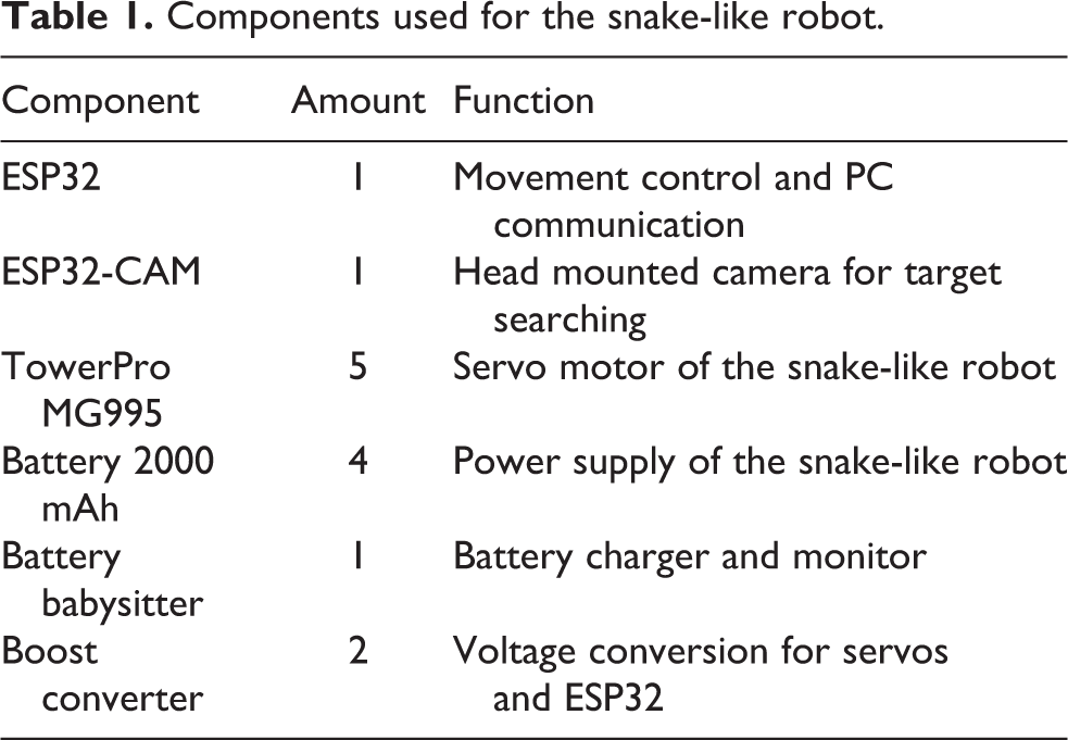
An upper part or a head part, together with a bottom part, composes a module that can rotate 180° about its axis. Figure 1(d) shows the assembled snake-like robot, which consists of five of such modules. It is noted that different colors are employed on the head module, the second module, and the tail module of the robot for pose tracking by an overhead camera (see “Environmental perception” section). Table 1 lists the hardware components of the snake-like robot. Communication between the snake-like robot and the graphical user interface (GUI) on a PC is established by the Wi-Fi module on the ESP32 component. All computation related to image processing is performed on the PC.
Components used for the snake-like robot.
Gait generation
As described in the “Introduction” section, snake-like robots are able to generate rhythmic movement by means of coordinating all the modules they have in proper temporal sequence and thus generating traveling waves for propulsion. There have been a number of control methods developed for locomotion generation of snake-like robots, such as the gait table method, 27 the analytical method, 8 and the bioinspired method. 28
Among these methods, the sinusoidal generator, characterized by its simplicity and capability of 3-D gait generation, is considered one of the most efficient approaches for gait generation. Followed the work by Gonzalez-Gomez et al., 29 we implement the control model using two groups of sinusoidal generators

where
There are seven gaits that have been implemented for the snake-like robot, including forward, backward, turning, clockwise (CW) and counterclockwise (CCW) rotating, and left and right sidewinding. In this study, we set
Gait parameters.

CW: clockwise; CCW: counterclockwise

Example gaits for (a) forward, (b) turning, (c) CW rotating, and (d) right sidewinding. CW: clockwise.
Control flow
Figure 3 shows the control flow of the vision-based target exploration system for snake-like robots. The snake-like robot system includes the snake-like robot itself and visual sensing information derived from onboard and environmental cameras. As described in the “Gait generation” section, the snake-like robot is able to perform different locomotive gaits by means of sinusoidal generators. Therefore, it is possible for the snake-like robot to switch among the gaits to avoid collision during navigation. A GUI is developed for three levels of interaction with the robot. Through the GUI, one can remotely observe the robot’s navigation in the environment, provide further information when the robot reports suspicious target images, and even manually control the robot for target searching. In addition, the snake-like robot is designed to be able to navigate in an autonomous manner from localization, planning to tracking. The navigation will stop once the target is found. For details, refer to the “Vision-based navigation” section.
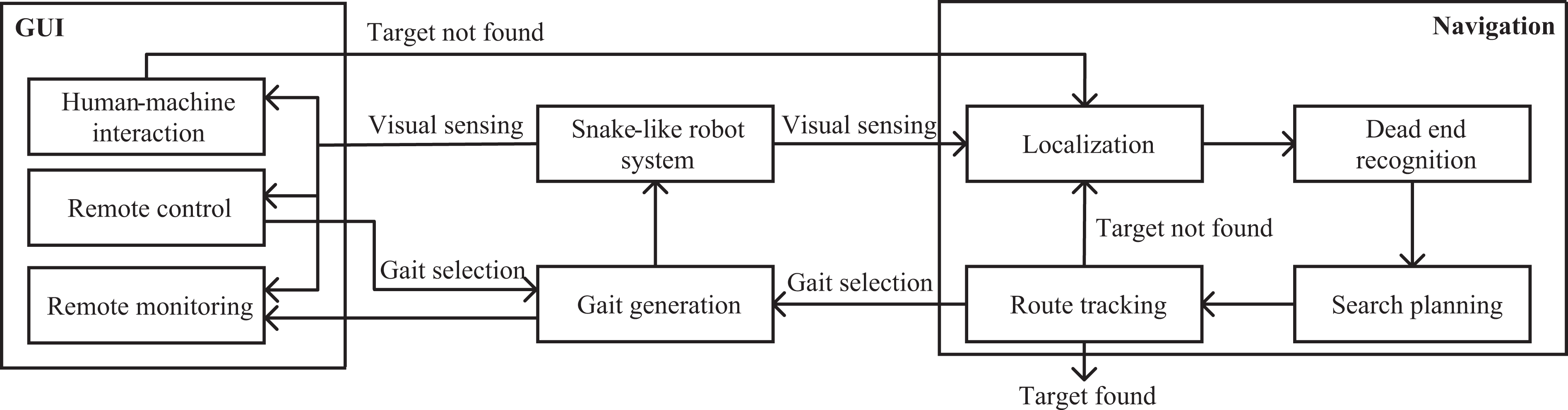
Control flow diagram.
Vision-based navigation
This section presents the details of the vision-based navigation system applied to the snake-like robot for target exploration. We take a maze example to illustrate how the robot perceives the environment, makes plans, and follows tracks for exploration.
Environmental perception
An overhead camera is employed above the maze, serving as an auxiliary sensor for the snake-like robot. The whole maze is within the field of view of the camera. The camera plays two roles in identifying the exploration environment and providing location of the robot in the maze.
The Canny edge detector is applied to detect the edges of the maze. First, the intensity of the gradients in two dimensions of the image is computed, followed by the non-maximum suppression for identifying the location with the sharpest change of the intensity value. After the suppression operation, two thresholds, one for identifying strong edges and the other for suppressing noise of edge pixels and identifying weak edges, are applied to the image. Then a probabilistic Hough transform is employed to further find sets of pixels that make up these straight lines. As a result, a black-and-white image representing the maze together with a set of coordinates of the corresponding lines can be obtained.
To be able to find the snake-like robot easier in the maze, we color the surface of the first two modules and the tail module in red, green, and purple, respectively, as shown in Figure 1(d). The distinguishable colors make it relatively easy to set masks and thresholds for removing the surrounding of the robot. After thresholding the image through the different masks, dilation and erosion are applied to the result of the masks to remove noise pixels. Contours are extracted from the result and the coordinates for the center of these colored modules are obtained.
Collision avoidance is one of the key issues to be solved when the snake-like robot navigates in the maze. As the location of the robot can be obtained by the overhead camera, we make use of the first two colored modules of the snake-like robot and utilize virtual sensors to achieve collision detection. Figure 4 depicts how the virtual sensors are designed for the snake-like robot. There are five virtual sensors employed on the snake-like robot. Three of them are mounted on the head module of the robot with a range up to 210° for front collision detection; the other two sensors applied on the second module of the robot with a range of 30° play a role in side collision detection. All the virtual sensors are constructed as sectors with a radius of 75 pixels. The virtual sensors will take effect as far as there are intersections between the lines of the maze and the sectors. The snake-like robot will cancel the normal movement and perform evasive maneuvers based on the position of the triggered virtual sensors.

Virtual sensors on the snake-like robot.
Path planning and tracking
Given the start and the end positions of the snake-like robot in the maze, planning a path will make the navigation more safe and efficient. So far, there have been various planning methods, such as potential field method, Dijkstra’s algorithm, and RRT. 19 In this study, we attempt to use both RRT and RRT*—a variant of RRT that can converge to an optimum, for path planning. Based on the work by Sakai et al., 31 some modifications, such as changes of obstacle type from circles to lines and the way to iterate forward, have been made to incorporate the maze exploration task. For every time when the algorithm creates a random node, it will find the nearest node and try to iterate from that node to the new random node. It has a certain probability of generating the random node that goes straight toward the goal to make the iteration more efficient.
Figure 5 shows the examples of planning results of RRT and RRT* in a maze. We set an edge distance of 30 pixels to keep the snake-like robot from collision with the maze. From the comparison, it is evident that the path by RRT has many twists and turns, whereas the path by RRT* is more linear and smooth. Considering the tracking efficiency of the snake-like robot in the next stage, RRT* is more suitable to this maze exploration task.
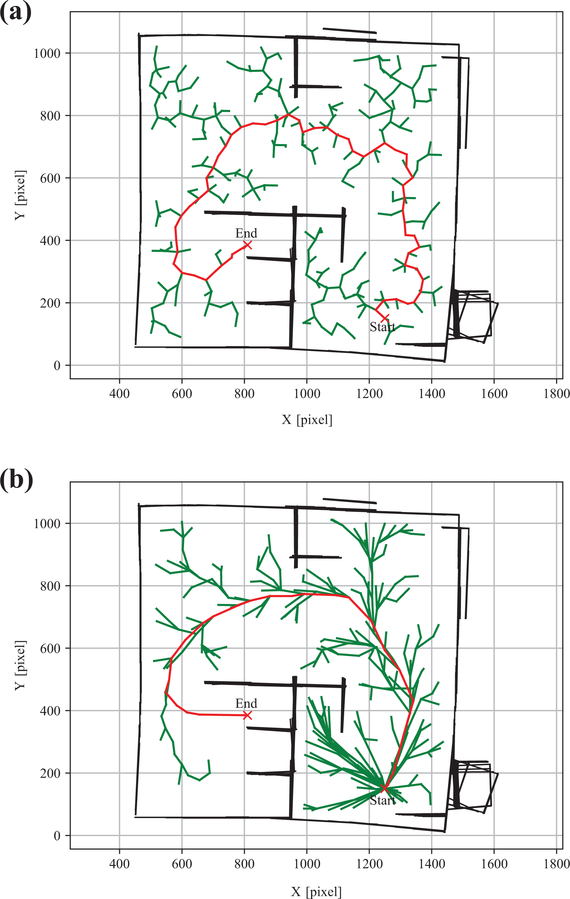
Examples of planning results using (a) RRT and (b) RRT*. RRT: rapidly exploring random tree.
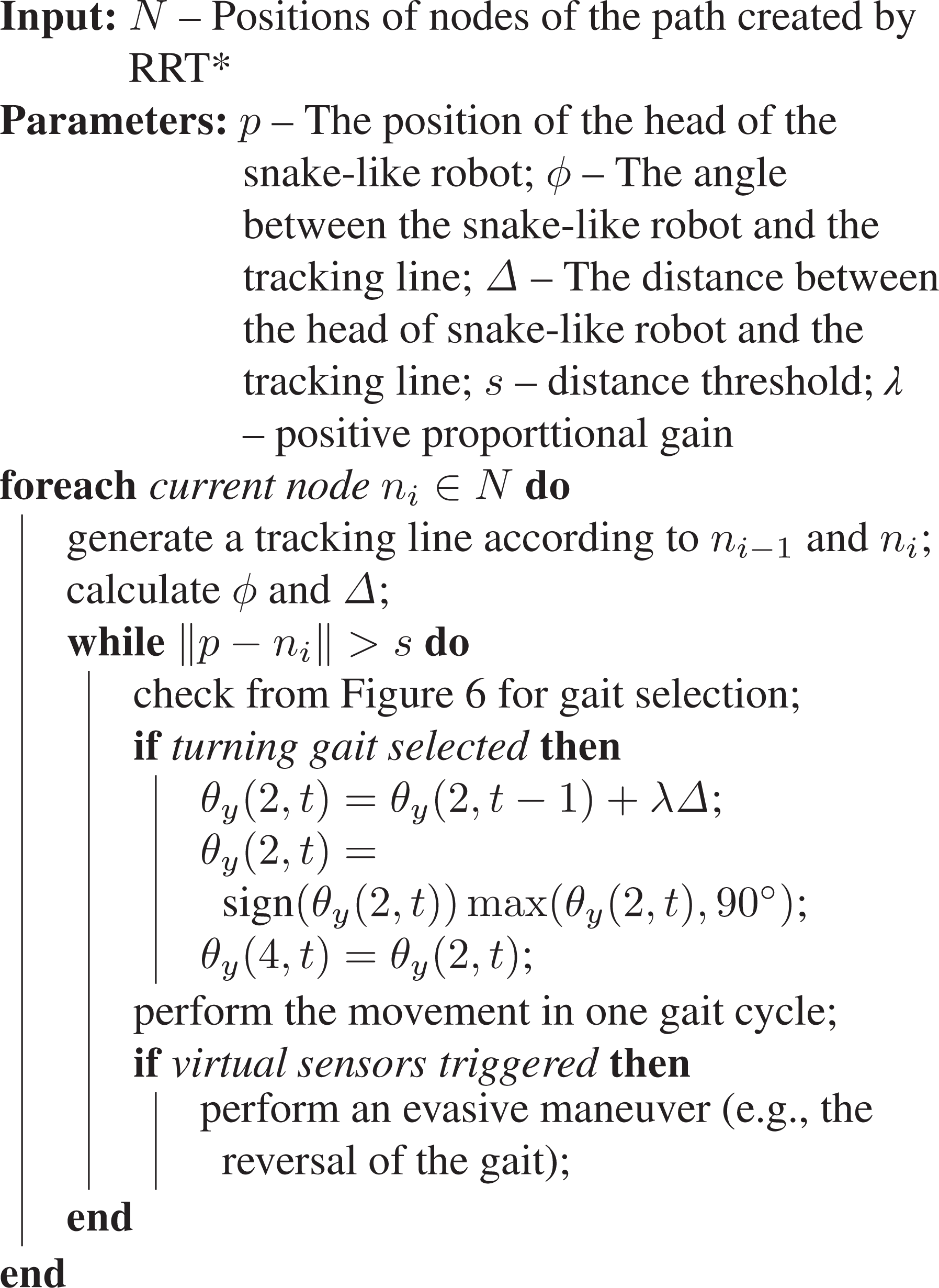
To follow a planned path, the snake-like robot needs to successively track each node in the path. Here, the head module of the robot is set as the position reference of the robot. This will facilitate distance computation and space preservation for taking pictures from the head camera. The solution to the tracking problem is to generate a sequence of gaits so that the robot can move toward the desired waypoint. According to the distance and the angle between the robot and the path, different gaits will be selected during the tracking, as shown in Figure 6. The detailed tracking strategy is illustrated in Algorithm 1.

Gait selection for the snake-like robot.
Path following algorithm.

Target exploration
For simplicity, there is only one target placed in the maze and the target is in yellow that it can be easily recognized by the head camera of the snake-like robot. It should be noted the snake-like robot only has the knowledge of the target, but no information about its location in the maze at all.
Since the target has a high probability to be placed in the dead ends of the maze, the dead ends need to be recognized for global planning in the maze. A template-based dead-end recognition is employed in this study. First, templates are generated by clipping out images of maze where dead ends are identified manually. Then, each template is checked by sliding it over the test maze image to compare patch of the maze image under that template image. The comparison returns a value of how similar the template is to a given spot in the maze. Once the value exceeds a threshold, the spot is recognized as a dead end, and the center coordinate of the spot is recorded for later use. Figure 7 shows an example of the result of dead-end detection in a maze.

Dead-end recognition in a maze.
Suppose there are m dead ends in the maze. To find out the global optimized traversal of all dead ends, one has to run the RRT* method
Experiments
The experiment setup is shown in Figure 8. A maze with a size of 1.5 × 1.5 m2 is constructed, in which the layout can be easily adjusted by the blue holders. The overhead camera is hanged over the maze with a distance that fits the maze inside the frame of the camera. The snake-like robot with a length about 0.45 m together with the target is randomly placed in the maze. A laptop equipped with an Intel Core i7 processor and 16-GB RAM is used for data exchange and image processing.

Experiment setup for target exploration in a maze.
Path tracking experiment
A path tracking experiment is carried out to verify the tracking performance of the snake-like robot. First, a simple maze is established. Then, the robot and the target are placed at
Figure 9 illustrates the screenshots of the tracking result from the overhead camera. By switching between gaits, the robot successfully follows the planned path and reaches the destination in about 75 s. The result of gait changes as well as the turning angles is depicted in Figure 10. In the first 5 s, the robot attempts to make CW rotation for changing its orientation toward the planned path. A risk of collision is then detected by the virtual sensors. The robot responds to make lateral shift and move backward to avoid to collide with the wall in the maze. From time 10 s to 52 s, the robot frequently switches between the turning and forward gaits, occasionally mixed with sidewinding and CCW rotating gaits, to keep its body as close as possible to the planned path. Since the middle part of the path is straight, the robot just moves forward until a turn of the path occurs. The robot then turns to the right to follow the path from time 63 s to 69 s. Once it passes the turn of the path, it changes back to the forward gait and arrives the destination in 6 s.

Screenshots of the path tracking experiment.

Gait changes of the snake-like robot in the path tracking experiment.
Dead-end search experiment
To verify the ability of the vision-based exploration system, a dead-end search experiment is conducted. A maze with the same size to the one in the “Path tracking experiment” section is constructed. The inner walls are modified so that more spaces are set aside for the movement of the snake-like robot. In this case, four dead ends are identified according to the template-based method described in the “Target exploration” section. The initial pose of the robot is set at
The traversal of the four dead ends follows the search strategy of dead ends described in the “Target exploration” section. Three successive paths in CCW direction are thus generated by the RRT* algorithm. By applying the path following method described in Algorithm 1, the snake-like robot navigates along these paths until the target is found. The whole procedure lasts about 218 s. Figure 11 shows the screenshots of the search result from the overhead camera. Each row of the figure corresponds to the tracking result of each path, respectively. It is obvious that the snake-like robot is able to track the paths. However, more attempts are made by the robot, for example, at the time 28, 86, and 131 s, for the transition from one path to the other path. The trigger of evasive maneuver due to collision detection by virtual sensors makes the robot move back and forth to adjust its pose to adapt to path changes.
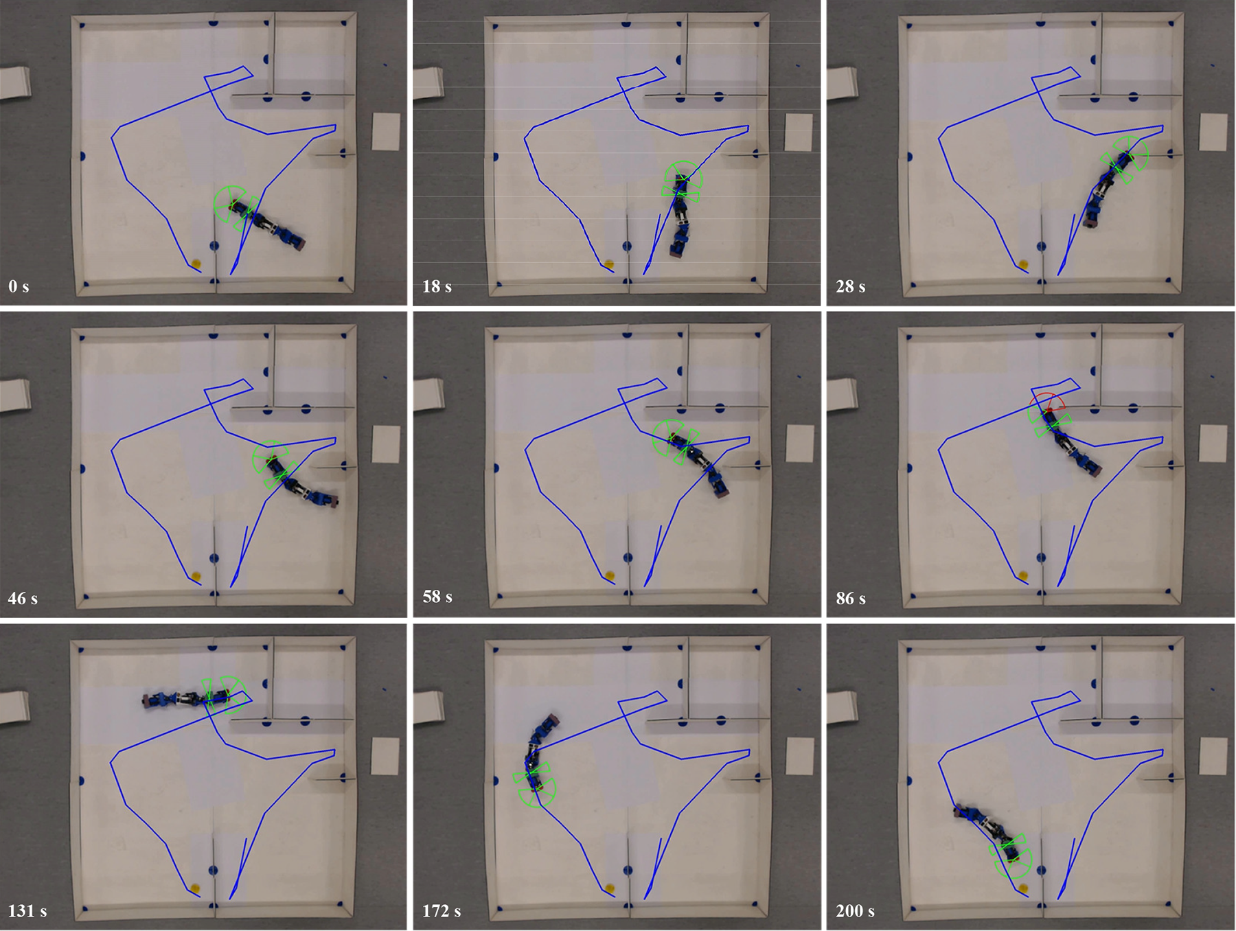
Screenshots of the dead-end search experiment.
Figure 12 shows the switch of gaits and the images obtained at each dead end. From Figure 12(a), turning and forward are the majority of the gaits the robot used for path tracking. There are also certain amount of sidewinding and rotating gaits occurred during path tracking. Thanks to the wide space in the maze, the robot does not collide with the maze when applying one of the two gaits. It is noted that an idle gait is added. It corresponds to the time period when the robot reaches a dead end and keeps still for image capture. This procedure lasts about 10 s. After the image is captured, a simple color detection is performed for target recognition. In Figure 12(b), the four positions from A to D are the places where the robot takes the images, and the arrows represent the direction of the head camera of the robot. From the result, the robot succeeds to follow the paths and discover the target at the last dead end.
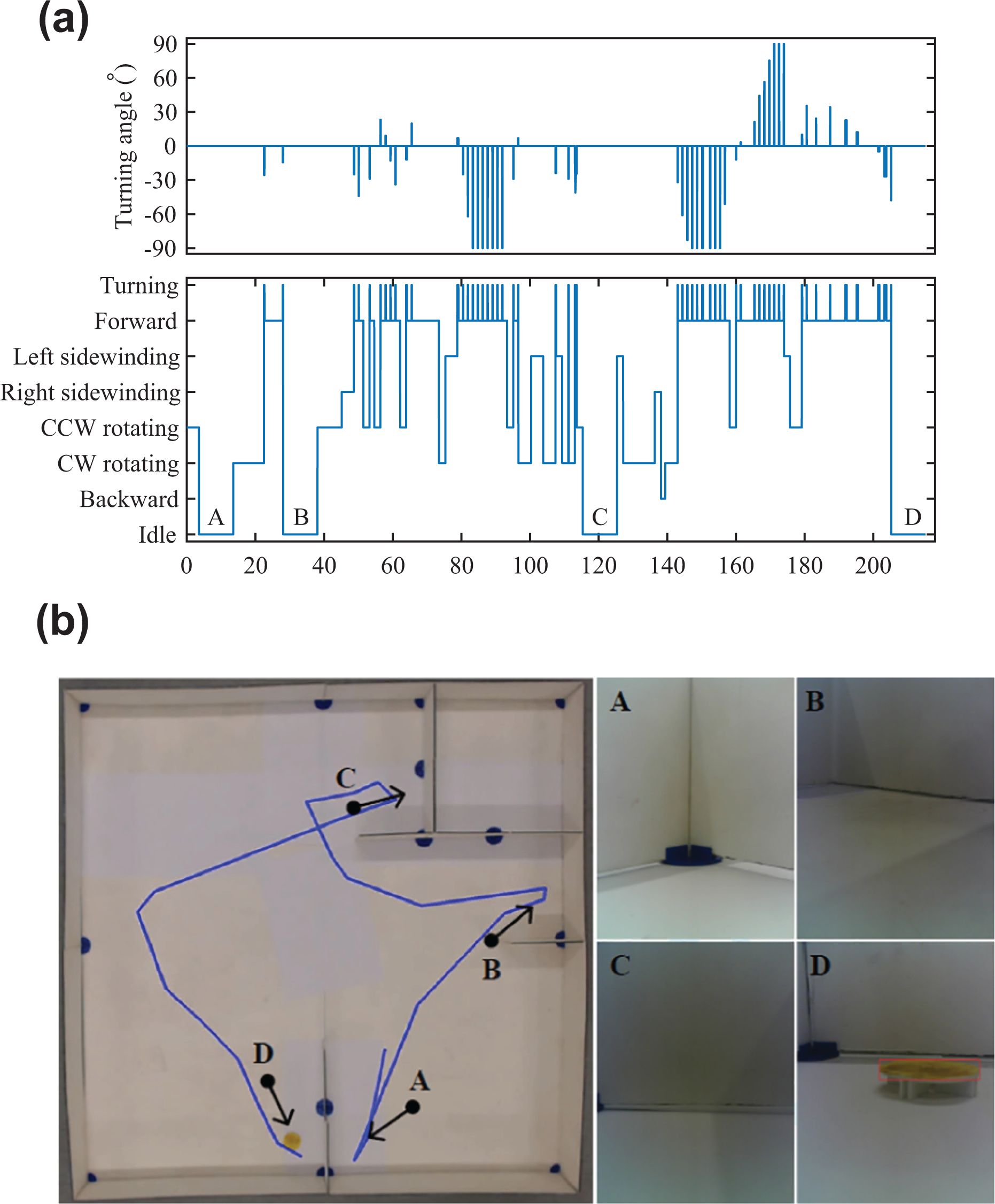
The results of (a) gait changes of the snake-like robot and (b) captured images from the head camera in the dead-end search experiment.
Discussion
From the experiments, it can be seen that the proposed vision-based exploration system works well on the snake-like robot. Here, we discuss some potential improvements to the system.
The edge distance in the RRT* algorithm plays an important role in the maze experiments. It prevents the robot from collision with the walls of the maze. However, from Figure 11, the edge distance cannot guarantee that the robot has enough space to lateral shift or rotate when the path is close to the wall. This may result in extra evasive maneuvers when the robot switches gaits. A higher value of edge distance may help, but it will narrow down the search space and even fail to find available paths. Therefore, the trade-off between the available paths and the amount of evasive maneuvers needs to be considered before applying the robot to a new maze.
There are sharp turns at the dead ends where two generated RRT* paths are connected. The results from Figures 11 and 12 show that they lead to inefficient tracking of the snake-like robot. Indeed, the sharp turns are unnecessary, as there is no need for the snake-like robot to take pictures at the exact location of the dead end. An alternative is to design a mechanism to create a shortcut of the sharp turn and thus reduce the collision probability and the tracking time.
The search strategy among the dead ends is another possible improvement of this study. From the “Target exploration” section, the search strategy relies only on the metric of the length and the curvature between the robot and the next dead end. This is efficient when there are a few dead ends, such as the maze in the “Dead-end search experiment” section. If the maze is big and complex, it becomes time-consuming for ranking all of the dead ends. Therefore, a pruning algorithm is needed to reduce the number of dead ends to be evaluated. In this way, a suboptimal solution can be achieved in reasonable time.
To sum up, the proposed vision-based exploration system is able to navigate the snake-like robot in the maze environment. Nevertheless, greater efforts are needed to improve the system to achieve fully autonomous navigation.
Conclusion
In this article, we introduce a vision-based exploration system that can be used by a snake-like robot for navigation in structured environments. First, a head camera is integrated into the mechanical design of the snake-like robot to achieve visual sensing during navigation. Seven types of gaits based on sinusoidal generators are developed so that the robot can adapt to the environment. Next, we apply an overhead camera to perceive the environment, such as the location of the robot and the surrounding structure. Then, a template-based method is utilized for dead-end detection in the environment, and a search strategy among the dead ends is employed for path planning. Using a path tracking algorithm, the snake-like robot can navigate along the planned paths for target exploration. We carry out target exploration experiments in a maze environment. The results show the proposed system is able to navigate the snake-like robot to search for the target.
For future work, we will focus on (1) adding distance sensors on the snake-like robot for better perception of the environment, (2) refining the path planning algorithm by taking the characteristics of the gaits into account, and (3) improving the search strategy in terms of time and distance.
Footnotes
Declaration of conflicting interests
The author(s) declared no potential conflicts of interest with respect to the research, authorship, and/or publication of this article.
Funding
The author(s) received no financial support for the research, authorship, and/or publication of this article.