
Abstract
In this work, a path planning strategy for both a car-like and a unicycle type assistive vehicles is presented. The assistive vehicles are confined to restricted environments. The path planning strategy uses the environment information to generate a kinematically plausible path to be followed by the vehicle. The environment information is provided by a SLAM (Simultaneous Localization and Mapping) algorithm implemented on the vehicles. The map generated by the SLAM algorithm compensates the lack of sensor at the back of the vehicles' chassis. A Monte Carlo-based technique is used to find the optimum path given the SLAM information. A visual and user-friendly interface enhances the user-vehicle communication allowing him/her to select a desired position and orientation (pose) that the vehicle should reach within the mapped environment. A trajectory controller drives the vehicle until it reaches a neighborhood of the desired pose. Several real-time experimental results within real environments are also shown herein.
1. Introduction
Maneuverability of assistive vehicles is currently dependent on the user/driver skills. Furthermore, for indoors vehicles, their movements are restricted by the structure of the surrounding environment. In hospitals or rehabilitation centers, assistive vehicles are used for medicine-carrying, assistance for the elderly and disabled people and for patient transportation (see, e.g., (1; 2)). Although these vehicles provide a solution in the assistance field, their lack of intelligence to move autonomously into unexpected situations or unknown environments limits their functionality to basic user dependent behaviors. The robotics field offers a wide spectrum of solutions to be applicable into the assistance and rehabilitation areas. Moreover, the mobile robotic tools can be directly applied to the assistive vehicles to improve the assistance task. Thus, several tasks can be relegated from the user control (i.e., user's efforts) to be commanded in an autonomous way, optimizing time and resources of the vehicle.
Generally, the unicycle type mobile robots are circumscribed by a circle, thus, the robot can be considered as a point and the obstacles are avoided according to the radius of the circle to plan a path or to avoid an obstacle reactively. In robotic wheelchair, that approach can not be used in confined spaces, because the circumscribed circle could be too big and some passageways could become non-navigable. On the other side, the movements of wheelchairs are restricted by the environment more than other unicycle type vehicles. For example, if the wheelchair is too close to a wall, it cannot rotate freely because the front or back may collide with the wall. Other case is when the goal point can only be attained by the wheelchair if it is correctly orientated. This case is illustrated in Fig. 1.

Example of wheelchair in a confined environment. The initial posture is marked by A and the goal posture is marked by B.
The limited steering angle in the car-like assistive vehicles restricts their maneuverability, which implies that in some confined environments the vehicle cannot attain its objective with a smooth trajectory. For example, turning back or turning ±90 degrees within narrow passageways.
In open spaces, the classical Dubins' results ((3; 4)) can be used to obtain a minimal length path for car-like vehicles. The resulting path consists of straight line segments or arcs. The radius of the arc is restricted by the minimum turning radius of the vehicle. However, in confined spaces, like the one shown in Fig. 2, the Dubins' approach is not valid because the walls restrict the space of maneuverability. Thus, a different approach is required to deal with the restriction imposed by the environment to the vehicle's movements.
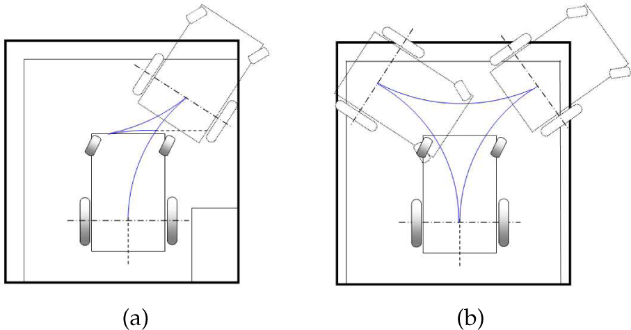
Path planning based on Dubins' results. a) The figure shows the case when the robot has to turn to the right of the passageway. On the other hand, b) shows the case when the robot has to turn back within the passageway. The blue lines represent the planned path.
A pose control (position and heading control) in open spaces for car-like vehicles is shown in (5). That work proposes a pose control in two stages. In the first stage the vehicle is controlled to converge to a line which contains the desired position and has the same orientation than the desired one. In the second stage the vehicle is controlled to converge to the desired position keeping constant the vehicle's heading. To deal with the space limitation due to walls or obstacles, the sign of the vehicle velocity is switched. However, a singular case may appear when using this method. The work of (6), applies receding horizon control method as a real-time optimization. By applying the method, desirable control is realized for the car-like robot's garage parking problem even if there are unexpected obstacles in the workspace. However, this method presents local minima when the vehicle is stacked near the wall or obstacles.
The cited works propose solutions for driving a car-like mobile robots in confined environments based on switching of moving directions. However, these works do not guarantee that the vehicle will attain the objective using their strategies.
Path planning algorithms and methods provide to the vehicle the coordinates of a plausible path within the environment of navigation. Two main categories of planning can be found in the scientific literature: local planning and global planning ((7)). The local planning is related to the maneuverability strategy from a local reference frame attached to the vehicle's motion. In some cases, reactive navigation (such as sensor-based navigation) is used instead of planning ((7; 8)) because of the small amount of environment information used by the robotic vehicle. Examples of this is the work of (9), where the vehicle instead of planning, uses range sensor laser information to instantaneously avoid obstacles within the environment. On the other hand, the woks of (10) is an example of local planning. In these works, a navigation objective is determined within the local point of view of the mobile robot and a trajectory controller drives the vehicle to the objective of navigation. The information of the environment used in the local path planning strategy is restricted to the sensors measurements at the pose of the mobile robot.
On the contrary, a global map is not attached to the mobile robot's pose. It is usually a fixed point of the environment to which all information should be referred ((7)). A global path planning strategy uses the information provided by the global map to generate a plausible path between the vehicle and the objective of navigation based on the planning criterion. Different planning criteria have been proposed by the scientific literature (see (11; 12)).
Once the optimization criterion has been established, a search method or algorithm finds the best path between all the possibilities. For example, the Dkjstra algorithm ((11)) is widely used by the scientific community to find minimum cost paths ((11)); also the A*, the Graphs method and the grid-based techniques ((13)) are examples of global planning methods. A more complete description of global planning techniques can be found in (11; 12). A common situation of the global path planning methods is that they use the environment information to generate the appropriate path but the way the information was acquired is usually not considered. Thus, the mobile robot follows a path generated by a path planning algorithm that uses prior map information ((13)) which is not necessary related to the sensors available on the vehicle. Thus, for example, the graph method ((8)) cannot be used if the mobile robot has sonar sensors to acquire range measurements because of the dispersion of the ultrasonic readings; the graph method requires a prior precise knowledge of the map of the environment. In order to use the environment information, a mapping process should also be included within the planning strategy.
Simultaneous localization and Map building (SLAM) is a challenging field of research of the mobile robot area ((13; 14)). The SLAM algorithm is advocated to minimize the errors involved in the localization and mapping processes, returning a reliable estimation of both: the pose –position and orientation– of the robot within the environment and the features from that environment. Self-localization of mobile robots is a fundamental issue in autonomous navigation: a mobile robot must be able to estimate its pose within a map of the environment it is navigating ((15; 16)). However, in many applications of practical relevance (like exploration tasks or operations in hostile environments), a map is not available or it is highly uncertain. Therefore, in such cases the robot must use the measurements provided by its sensory equipment to estimate a map of the environment and, at the same time, to localize itself within that map.
Several techniques have been proposed to solve the SLAM problem, such as the Extended Kalman Filter (EKF) ((17; 18)) which is one of the most used filters in SLAM ((13)). The EKF uses linearized models of the robot motion and the environment. The estimation process considers the system state as a Gaussian random variable. The map constructed by the EKF-SLAM algorithm is usually composed by geometric features from the environment. The work of (16) shows an EKF-SLAM based on the extraction of lines from the surrounding environment whereas the work of (19) shows a point-based map (trees were modeled as point-based features). The Information Filter (IF) is another solution to the SLAM problem. It is primary used to solve the processing time problem of the EKF ((20)). The Unscented Kalman Filter (UKF) is another approach ((13)). The main contribution of the UKF is the managing of the non-linearities of both: the measurement and the motion model. More recent approaches use the Particle Filter (PF) as a solution to the SLAM problem. The PF-SLAM ((13)) does not depend on the non-linearities of the models and it is not sensitive to non-Gaussian distributions. Although it seems to be a better solution, the high processing time involved within the estimation process makes it unsuitable for real time implementations. For example, PF-SLAM based on grid maps (Fast-SLAM) presented in (13), presents a very accurate map reconstruction which is performed after the navigation process takes place.
In this work, a path planning strategy for assistive vehicles (both: unicycle and car-like types) operating in confined spaces is developed combined with a visual interface. The path is composed by semi-circle arcs which lengths are limited by the walls or obstacles of the environment. The Monte Carlo technique is used to find the radius of these arcs in order to obtain the optimum path according to a cost function. A SLAM algorithm is implemented to extract a map from the environment and to localize the vehicle. Also, that map is used during the maneuverability strategy since the vehicles used in this work, only have range sensors at the front of their chassis. Therefore, the safety of the backward movements is associated with the SLAM performance. Although this work uses an EKF-SLAM algorithm that extracts corners and lines from the environment, the path planning strategy presented herein does not depend on the type of SLAM algorithm used (as long as the SLAM algorithm allows a geometric-based reconstruction of the environment). The objective of the path planning can be divided into three: to turn the vehicle until a desired heading is attained, to reach a given point from the environment and to reach a given point from the environment with a desired orientation. A trajectory tracking control is used to drive the vehicle over the planned path. A visual interface enhance the user-vehicle communication, providing a friendly interface to command the vehicle's motion through the environment. Many experiments are performed herein to show the functionality of the proposed system.
2. Related Work
As was stated in section 1, the maneuverability problem for vehicles is a latent issue for assistive applications. Either for kinematic constrains (such as in car-like mobile robots) or for dimensions constrains (such as in motorized wheelchairs), the maneuverability problem has been studied during the last years by the scientific community.
The solutions to the maneuverability problem of assistive vehicles can be divided into two: a human-computer interface based solution and an intelligent control solution. Among the human-computer interfaces based solutions, the effort was concentrated on linking the user's capabilities with the mobile robot system. Thus, the work of (21) presents a camera based joystick. The system detects the movements of the head of the user and thus it generates the motion commands of the robotic wheelchair. The work of (22) presents a Brain-Computer Interface (BCI). This BCI generates a finite state machine based on evoked visual potentials. Each state of the BCI is associated with motion commands of the robotic wheelchair. Therefore, the user is able to command the robotic wheelchair by means of his/her evoked visual potentials. Due to the fact of the limitations of generating evoked visual potentials, the speed of the finite state machine associated with the BCI is limited by the user's learning. Also, the work of (23; 24) show different examples of BCI's combined with rehabilitation devices. The work of (25) presents a Muscle-Computer Interface (MCI) to command a mobile robot motion based on supination and pronation movements. In this research line, the works of (26; 27) also offer different applications of MCI to command a mobile robot. Despite of the human-computer interface used, the common denominators of the work presented before is that the body of the user is considered as a sophisticated joystick. The joystick device, when used, it is associated with the user capabilities. Thus, we can find hand-joysticks, joystick governed by the tongue and by feet ((28)), etc.
On the other hand, the intelligent control solutions to the motorized wheelchair maneuverability problem involves the human-computer interactions, the learning algorithms and the control system design to drive the vehicle in a safe manner. Thus, the work of (29) presents an intelligent wheelchair that allows the user to avoid obstacles and plans movements by means of a visual interface. The work of (30) presents a maps managing algorithm for robotic wheelchair systems. The maps managing algorithm allows the storage of multiple real maps from known environments. Thus, if the user of the wheelchair has to go to a specified location within a stored map, then the system generates a feasible trajectory to drive the vehicle to the desired position. This work uses the Dkjstra ((11)) algorithm to generate the best path from all possible solutions and it considers the kinematic constrains of the vehicle. Another example is the work of (31), where the authors present a strategy to deal with populated environments when navigating a motorized wheelchair.
Although the presented works offer different solutions to the maneuverability problem, they do not manage the lack of environment information problem. Thus, the robotic wheelchair is considered as a point for control purposes, therefore, environmental restrictions are not considered. For example, the robotic wheelchair presented in (32) is 1.2 meters long and 0.7 meters wide. If that wheelchair were located within a 1 meter wide corridor, it would probably will not be able to turn back without a great effort of the user. Furthermore, considering that the user's capabilities might not allow him/her to look back, then an intelligent control technique should assist the user when executing this kind of tasks. For this specific problem, the authors have already published experimental and theoretical solutions ((33–36)). Although, these solutions are concentrated in guiding the robotic wheelchair to a desired orientation within the environment. In this work, we extend our solution to guide the assistive vehicle to a desired point and/or a desired orientation. Also, the visual interface that we present in this work can be adapted to the user's capabilities.
3. System Architecture
Figure 3 shows the general system architecture presented in this work.
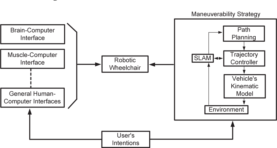
General system architecture.
Figure 3 can be briefly summarized as follows.
While the robot is driven within the environment, it performs a SLAM algorithm to acquire a feature-based map of the environment and to localize itself minimizing errors. Once the turning algorithm is invoked, the system uses both the map information and the vehicle's pose estimation provided by the SLAM to generate an obstacle-free semi-circle inspired trajectory which switches the direction of the motion according to the map disposition. The benefits of using SLAM are shown in the reverse drive of the robot due to the fact that the vehicle does not have range or proximity sensors at the back of its chassis. The SLAM allows the vehicle to drive safely. A kinematic trajectory controller is used to drive the vehicle. Once the vehicle has reached the desired orientation/position/postion&orientation it stops its execution. The vehicle returns to its navigational operation modus.
Figure 3 shows the different Human-Computer Interfaces (HCI) that can be used within our maneuverability strategy proposal. Though we are using a hand-based joystick, the system could be adapted to the user's capabilities. The motion control generated by the HCI is directly sent to the robotic wheelchair. In this case, the user has a full control of the vehicle. Once the user has to reach a desired orientation, position or both, the wheelchair's control passes to the Maneuverability Strategy.
Once the user has to attain a desired orientation and/or position, the path planning strategy generates a Monte Carlo based set of feasible paths. Only one path is chosen based on a predefined criterion. In this work, we have used the kinematic energy associated with a path as a criterion to chose the best path. The path generation stage uses both: the robot position and the environment information to generate feasible paths. This information is passed by the SLAM algorithm. The SLAM algorithm is implemented on an Extended Kalman filter (EKF) and extracts corners and lines from the environment. The corners can be both: concave or convex and lines are associated with walls from the environment.
Once a path is chosen, a trajectory controller generates the driving commands to control the robotic wheelchair motion which, in turn, interacts with the environment. The following sections will explain in detail each of the blocks of Fig. 3.
3.1 Human-Robotic Interface
The visual interface used in this work allows the user to choose both, the desired orientation and/or the desired final position by means of a hand joystick. Considering that the hand joystick is also used during the non-autonomous navigation of the robotic wheelchair, some considerations must be taken into account. Thus, if the maneuverability strategy presented in this work is not required by the user, the full motion command of the robotic wheelchair remains on the hand joystick governed by the user. Once the user has to maneuver within a confined space, the control of the robotic wheelchair passes to the maneuverability system presented herein, but the decision must be taken by the user.
Therefore, in this work we have implemented a finite state machine specially designed to interpret the joystick commands. Then, let y J be the lean forward value of the hand joystick and -y J the respective lean backward value; let x J be the lean right value of the joystick and -x J its corresponding lean left value. Figure 4 shows the layout of the finite state machine presented herein. In Fig. 4, α J and β J are positive constants such that α J > β J , n J = √x2 J + y2 J y θ J = atan2{-y J ,x J }. The variables m J and θ J are defined as the magnitude and the orientation, respectively, of the joystick.
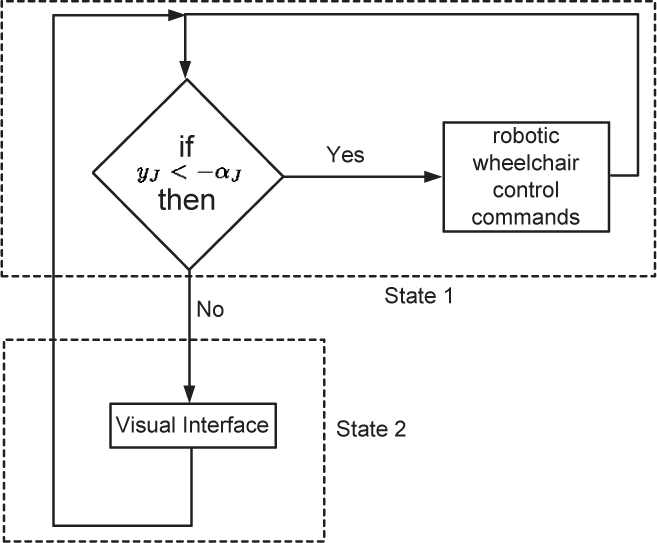
Finite state machine of the joystick associated with the HMI.
The finite state machine begins at the state “1”. Considering that it needs a signal from the joystick to leave the non-autonomous modus and start the autonomous navigation, the backward movement of the joystick is used to make such transition. The rest of the joystick movements will drive the robotic wheelchair in a conventional way when operating in a non-autonomous modus. The backward movement of the robotic wheelchair will be performed in a special way: it will be at very low speed and proportional to the joystick lean when −α J ⩽ y J < 0. When y J < −α J then the finite state machine passes from state “1” to state “2”. The state “2” represents the visual interface that will be explained following. To leave the visual interface and return to state “1”, the user has to generate a backward movement of the joystick such that y J < −α J . Figure 4 shows the general representation of the finite state machine used to command the robotic wheelchair.
The visual interface associated with state “2” in Fig. 4 is represented in Fig. 5. As it can be seen, Fig. 5 is represented by two screen: one screen is associated to the orientation desired by the user whereas the second screen is associated with the position desired by the user. To choose a desired orientation, the system works as follows.
The arrow at zero degrees –see Fig. 5– waits five seconds before starting the rotation. If during the five seconds of the last item, the user generates a backward movement with the joystick such that y
J
< −α
J
, then an angle scanning begins. The angle scanning is a moving arrow that starts at zero degree –from a local reference frame attached to the vehicle– up to 360 degrees, with a step jump of one degree. If during the angle scanning a backward movement of the joystick is detected with y
J
< −α
J
, then that angle is selected as the desired orientation for the planning strategy. Then, the control passes to the second screen to select the desired position within the map. (v) If after two angle scanning of 360 degrees the user does not select a possible orientation, the control passes to the second screen, in order to select a possible desired position.

Visual interface. The screen on the left shows how the angle scanning works whereas the screen on the right shows how the space scanning works. The map loaded at the screen on the right corresponds to the map generated by the SLAM algorithm. Solid red segments are associated with lines from the environment and the green dots are associated with corners.
The selected angle in the procedure explained before determines the desired angle that the wheelchair should reach based on the planning algorithm presented in this article. Once the control passes to the second screen, the user has the possibility of choosing a possible desired position within the environment constructed by the SLAM algorithm. This procedure works as follows.
The map of the environment is loaded within the second screen. This map is obtained from the SLAM system state, which has the parameters of the lines and corners detected from the environment. This map is held for five seconds. If during this time the user generates a backward movement with the joystick such that y
J
< −α
J
, then a scanning begins. This space scanning is equivalent to the one shown in (30). In this article, a blue circle scan the navigable space of the mapped area ((12)). The scan is performed horizontally (in Fig. 5, the line that is followed by the blue circle is the dashed black line). If the users choose a point that does not belong to the navigable space of the mapped area, then the visual interface quits without passing any reference to the planning strategy. The user is able to select a navigable point by generating a backward movement with the joystick such that y
J
< −α
J
. Then, the center of mass of the blue circle represents the desired orientation chosen by the user. If after two scans the user does not select a position, the planning algorithm is executed with the desired orientation information –if available–. Otherwise, the finite state machine returns to state “1”.
Thus, the visual interface of Fig. 5 can return the desired orientation, the desired position or both. In the following sections, the path planning algorithms will be explained for each case.
3.2 EKF-SLAM
The SLAM algorithm implemented in this work is a sequential EKF feature-based SLAM ((13)). The features extracted from the environment correspond to lines and corners -concave and convex-. The system state is composed by the vehicle estimated pose and the features of the environment. For visualization and map reconstruction purposes, a secondary map is maintained.
This secondary map stores the beginning and ending points of the segments associated with the lines of the environment. Thus, the secondary map allows finite walls' representation. The secondary map is updated according to the feature correction in the SLAM system state, and if a new feature is added to that system state, it is also added in the secondary map ((37)). Equations (1) and (2) shows the system state structure and its covariance matrix. All elements of the SLAM system state are referenced to a global coordinate system.


In Eq. (1), ◯(k|k) is the system state estimate; ◯ v (k|k) = [◯ v,x (k|k) ◯ v,y (k|k) ◯v,θ(k|k) T is the estimated pose of the vehicle; ◯ m (k|k) represents the map of the environment and it is composed by the Cartesian coordinates that define a corner and the polar coordinates that define a line in the environment. The order in which lines and corners appear in ◯ m (k|k) depends on the moment they were detected. P(k|k) is the covariance matrix associated with the SLAM system state; P v,v (k|k) is the covariance of the vehicle pose and P m,m (k|k) is the covariance of the features of the environment. The rest of the elements of the P(k|k) are the cross-correlation matrices.
The covariance matrix initialization techniques and the EKF definition can be found in (17; 18). A sequential EKF ((13)) was implemented in order to reduce computational costs.
The features extraction algorithm and modeling can be found in (25).
3.3 Robotic Wheelchair
The robotic wheelchair used in this work was developed by the Electrical Engineering Department of the Universidade Federal do Espírito Santo, Brazil –see Fig. 6–. The hardware architecture of the robotic wheelchair shown in Fig. 6 is composed by: a commercial electric wheelchair from which only motors and the mechanical structure are used; two encoders directly connected to the motors; a MSP430F1611 microprocessor –from Texas Instrument; an on board computer and range sensor laser (built by SICK). This laser acquires 181 measurements from 0 to 180 degrees, with a maximum range of 30 meters. The laser is used to extract corners and lines from the environment for the EKF-SLAM algorithm. All the algorithms developed herein were implemented on Windows operative system using Microsoft Visual C++.

Robotic wheelchair used herein.
As it can be seen in Fig. 6, the robotic wheelchair is a unicycle type vehicle. Its kinematic model is shown in Eq. (3).

In Eq. (3), u
t
is the linear velocity command whereas ω
t
is the angular velocity command; Δ
t
is the sampling time of the system; x
x
, x
y
, xθ are the position and orientation of the vehicle within a global reference frame;
3.4 Path planning problem
The path planning problem can be divided into three sub-problems according to their respective objectives:
Path planning to reach a desired orientation. Path planning to reach a desired position. Path planning to reach a desired orientation and a desired position.
The three problems will be analyzed within this section. In addition, the restrictions adopted to generate a feasible path can be summarized as:
The vehicle must follow a kinematic compatible path. The path must be obstacle-free. The vehicle is considered as a rigid body.
Thus, if the path generated by a path planning technique is not compatible with the vehicle's kinematics, then it would probably not succeed on its task ((8)). Also, a path should not cross any known element from the environment in order to avoid possible collisions. Within the same line, the robot is considered as a rigid body instead of a point in order to avoid collision risks.
Following, we present our path planning proposals.
3.4.1 Path planning first approach: Reaching a desired orientation
The path planning algorithm is inspired in the work of (5), where a linear trajectory was followed by a car-like robot to park it. In this work, the vehicle follows a semi-circle path. The direction of the driving changes when the vehicle is close to an element of the environment, as it is shown in Fig. 7. This process continues until the vehicle has successfully reached the desired orientation. Considering that the vehicle follows a semi-circle trajectory, the final path is a kinematic plausible path ((8)). Also, the radius of each arc is variable from zero –which represents the turn of the vehicle over its point of control– to infinite –which is associated with a straight line, therefore, the vehicle follows a straight line–. In the case of car-like robots, the radius are generated from the minimum radius of turning of the vehicle to infinity. The arc generation procedure is based on the Monte Carlo method. This procedure was previously presented by the authors in (33). The path generation procedure can be summarized as follows.
From the wheelchair's pose and having into account the map information provided by the SLAM algorithm, N arcs are generated. These arcs have different radius generated by the Monte Carlo method ((36)). The arcs go from the wheelchair's pose to the closest element from the environment. For each arc that reaches a neighborhood of an element from the environment, N arcs are generated from that precise point of collision but with an opposite direction with respect to the previous one. The entire perimeter of the vehicle is used to test whether a point of such perimeter intersects any element from the environment –and thus the vehicle is considered as a rigid body–. The arcs generation procedure continues until each arc has reached the user's desired orientation. If after M arcs, the path planning method does not find a plausible path for some specific orientation, such path is then rejected from the system. From the set of all successful path, that path with minimum kinetic energy associated with, will be chosen by the system to be followed by the assistive vehicle.

Example of the path planning method to attain a desired orientation. In this case, the path planning has to generate a feasible path to reach an orientation of −π/2 with respect to the vehicle's current position. N = 10 paths are generated, where each path should have no more than M = 5 arcs each.
Thus, the path planning problem is solved by a classical decision-tree problem ((11)), where the best path is the one that reaches the desired orientation and has the minimum kinetic energy. Further information about this topic can be found in (36). Figure 7 shows an example of the path planning algorithm with the radius' arc generated by the Monte Carlo method.
The path planning algorithm for this approach is shown in the algorithm of Fig. 8
In Fig. 8, line of code 3 presents the Quit variable. Thus, if Quit = true during the arc generation procedure –i.e., the arc has reached the desired orientation– that arc generation procedure is over and a feasible path is obtained. If Quit = false the arc generation procedure continues. Line of code 4 shows the user's desired angle ψ. This angle is obtained through the visual interface shown in Fig. 5; P paths in line of code 5 represents all the feasible paths obtained by the algorithm. In line of code 6, we introduce the virtual map (MAPv) that circumscribes the entire map generated by the SLAM algorithm, as it is shown in Fig. 7, by solid blue segments. This virtual map is necessary in order to restrict the space of maneuverability of the vehicle. In that way, the unknown space remains outside of the virtual rectangle. The segments of the virtual rectangles are modeled according to (16). In lines of code 7 and 8, SIDE = true implies that the vehicle will first try to turn to its right –SIDE = false represents a turning to the left– and DIRECTION = true implies that the first movement of the robotic wheelchair following a prescribed path should be backward –DIRECTION = false stands for the opposite: the first movement will be forward–.
The main for–loop (lines of code 9 to 25) shows the paths generation procedure whereas the inner for–loop shows a single path generation method. The path generation procedure starts with the radius generations based on the Monte Carlo method presented in (34)–line of code 12–. As stated before, the radius' values go from zero to infinity for wheelchairs and from the minimum radius of turning to infinity for the case of car-like vehicles. Once the radius of an arc is determined, the arc is generated based on the robot's current position and orientation, the map of the environment (SLAM information), the virtual rectangle and the current values of the SIDE and DIRECTION variables. The arc generation returns the coordinates values of the arc, its associated energy and whether or not the arc reaches the desired orientation (Quit variable). The arc algorithm can be found in (36). The arc energy is then stored –line of code 19–. The inner for–loop breaks when Quit = true. After all feasible paths were found, the one with the lower kinetic energy associated with it will be chosen as the final path to be followed by the vehicle. The coordinates information of the path is then passed to the trajectory controller.
3.4.2 Path planning second approach: Reaching a desired position
This second approach is not too different from the first approach. In this case, the objective of the planning is more complex but the same algorithm is used. In this second approach, the robotic wheelchair has to reach a position previously determined by the user by following a path that will most closely drive the vehicle to that position with the lowest user's effort. This is accomplished by implementing the following minimization criterion:

In Eq. (4), the minimization argument is a linear cost argument: Cost = Energy + distance, therefore, the path that has the lowest cost is the path that will be followed by the vehicle.
Figure 9 shows an example where the robot has to reach the position marked by a solid dot point. As it can be seen, the path planning technique generates a path close to the desired position but the reachability of that point is not ensured given the environmental disposition. In addition, the desired position parameter is passed by the user by means of the visual interface shown in Fig. 5.

Example of the path planning method to attain a desired position. In this case, the two best paths are shown in solid magenta. As it can be seen, the paths reach a point very close to the desired one –solid red point–. For this example, 100 paths were generated with 10 arcs for each path.
The algorithm shown in Fig. 11, represents the path planning procedure to reach a desired position within the mapped environment. As it can be seen, the procedure is equivalent to the one shown in Fig. 8 except in the way the best path is chosen –line of code 26–. Also, the arc generation function passes one extra parameter –distance– associated with the minimum distance of the points of arc to the desired position. The main for–loop breaks when the boolean variable Quit stands that the arc has reached a certain neighborhood of the desired position. This is necessary to ensure that the solution will be close to the desired position. The magnitude of the neighborhood must be previously determined by the designer.
3.4.3 Path planning third approach: Reaching a desired position and orientation
In this third approach, the user has chosen an orientation and a desired position from the interface shown in Fig. 5. These parameters (desired orientation and position) are passed to the path planning strategy. In this case, the path planning strategy tries to find the best path such that the robotic wheelchair be able to reach a neighborhood of the desired orientation and a neighborhood of the desired position.
The following minimization criterion is implemented within the path planning algorithm.

In Eq. (5), the minimization criterion implies that, from the set of all possible paths generated by the path planning method, only the one that minimizes the cost function Cost = Energy + distance + distanceAngle will be chosen to be followed by the mobile vehicle. distance Angle is the difference between the reached and the desired angle. Figure 10 shows the general form of the path planning algorithm, where the main difference with the algorithm of Fig. 8 is the minimization criterion shown in Eq. (5) and repeated at line of code 26 in Fig. 10

Path planning algorithm for attaining user's desired position and orientation.

Path planning algorithm for attaining user's desired position.
Figure 12 shows two different examples of the path planning algorithm proposed in Fig. 10. In lines of code 13 and 21, the Quit = true when the path has reached both neighborhoods: a neighborhood of the desired orientation and a neighborhood of the desired position.

Example of the path planning method to attain a desired position and a desired orientation. In this case, the best path is shown in solid magenta. The desired position is [x, y] = [10, 8.75] T is it is represented by a solid red dot. The desired orientation is ψ = π. As it can be seen, the paths reach a point very close to the desired one and with the desired orientation, although the rest of the paths are very different between each other. For this example, 10 paths were generated with 10 arcs for each path.
The algorithm shown in Fig. 10 does not ensures that a solution can be found that satisfies both conditions: angle and orientation, as can be clearly seen in Fig. 12, where only one path is close enough to the desired position and the desired orientation.
4. Control Laws
Once a path a generated by means of any of the three algorithms presented in this work (algorithms of Figs. 8, 11 and 10), the path coordinates are sent to the trajectory controller as was introduced in section 3.
Two control laws were implemented in this work: a trajectory controller and an orientation controller. The trajectory controller is used to follow the path generated by the path planning algorithm. The orientation controller corrects the heading error when a final posture is desired for the vehicle.
4.1 Trajectory Controller
The tracking control law for non-holonomic vehicles proposed in (38) is used in the present control system. This is an asymptotically stable control law whose stability was proved through Lyapunov theories. The inputs to the vehicle are the reference posture [x x r x y r xθ r ] T and the reference velocities [V r W r ] T .
The posture error is defined as follows:

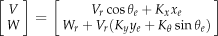
Kanayama also proposes a parameter selection to obtain a critical damping in the control. The damping of the tracking control can be calculated through

A critical damping in the control is obtained when ζ, = 1.
4.2 Orientation Controller
The kinematic orientation control law implemented in this work is shown in Eq. 8.


By replacing Eq. 8 and 9 in the kinematic model of the vehicle (see Eq. 3) the following holds.

Therefore, x˜θ → 0 as t → ∞.
5. Experimental Results
In this section we show de different experimental results for each proposal presented in this work. The experiments were carried out at the Engineering Department of the Federal University of Espirito Santo, ES, Brazil. The robotic wheelchair used is the one shown in Fig. 6.
As it is shown in Fig. 6, the robotic wheelchair has a laser
Figures 13 – 18 show the experimental results of the planning strategies presented in this work. For all experimentations, 2500 real time Monte Carlo realizations were carried out. During experiments, the mobile robot navigates within the environment while constructing the map by means of the SLAM algorithm until the vehicle has to manoeuver, in which case the planning algorithms presented in this paper are executed. Figures 13 and 14 show the planning strategy case without prescribing a final position (as it was previously shown in Fig. 7). The robot's initial posture is [10.7 8.0 π/2] T and has to turn until it reaches the orientation value of −π/2. In Figs. 15 and 16, the robot has to reach a neighborhood of the point [10.25 9.75]. As it can be seen, the path planning reaches such a neighborhood of the desired posture.

Monte Carlo Path Planning strategy without prescribing final position. This figure shows only ten possible paths obtained by the Monte Carlo experiment (solid black lines); the magenta circles are the the final position with the desired orientation. The solid grey lines are the walls of the environment and the solid blue segments are the virtual features of the circumscribing rectangle.
Controller results for the path planning strategy without prescribing final position. This figure shows the path traveled by the wheelchair –magenta points– and the path with the minimum cost –traveled by the wheelchair– determined by the algorithm shown in Fig. 8 –blue points–.

Monte Carlo Path Planning strategy for a desired final posture. This figure shows only ten possible paths obtained by the Monte Carlo experiment (solid black lines); the magenta circles are the the final posture of the robot in the neighborhood of the desired pose –solid green circle–. The solid grey lines are the walls of the environment and the solid blue segments are the virtual features of the circumscribing rectangle.

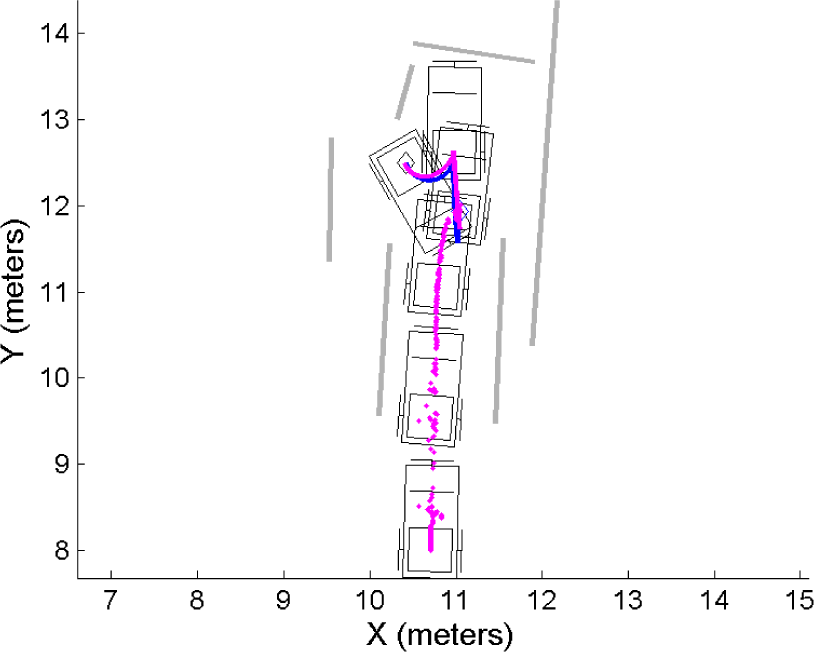
Controller results for the path planning strategy for a desired final posture. This figure shows the path traveled by the wheelchair –magenta points– and the path with the minimum cost –traveled by the wheelchair– determined by the algorithm shown in Fig. 10 –blue points–.
On the other hand, Figs. 17 and 18 show the path planning procedure when the robotic wheelchair has to reach its initial posture but with a different angle. Thus, in Fig. 17, the vehicle has to reach an orientation of zero degrees (its initial orientation is π/2) and in Fig. 18 the vehicle reaches an orientation of −π/2.

Maneuverability strategy results when the vehicle has to reach a desired orientation close to its actual position. In this example, the vehicle has an initial orientation of π/2 and generates a path that will lead it to reach an orientation of zero degrees near its current position. The solid red segments correspond to walls of the environment and the solid blue segments correspond to the virtual rectangle that circumscribes the map built by the SLAM algorithm. The solid magenta line is the path found as the optimum path. The planning algorithm used is the one presented in Fig. 10.

Second maneuverability strategy experiment when the vehicle has to reach a desired orientation near the wheelchair's current position. In this experiment, the path planning method generates a path to lead the vehicle to reach the orientation of −π/2. As in Fig. 17, the solid red segments are associated with lines from the environment –such as walls or doors– and the solid blue segments correspond to the virtual rectangle. The path chosen as optimum is in solid magenta.
6. Conclusion
An assistive vehicle navigation system for confined spaces was proposed. The SLAM algorithm provides enough information for the path planning and for the control strategy. The generated trajectories by the path planning module are typical trajectories that a user with enough drive skills could perform in a similar situation. One way to apply the system presented in this work is in a semi autonomous mode: the user drives the wheelchair until a difficult situation is presented caused by a confined environment, then the user selects from a visual interface, the position and/or the orientation within the SLAM-constructed map that the vehicle should reach. The visual interface is divided into two stages: one stage associated with the vehicle's final orientation selection and the other one associated with the vehicle's final position. Both stages are independent, therefore the user is able to choose a desired orientation and/or a desired position.
The path planning method based on variable Monte Carlo arcs generation presented in this work is used for the generation of a feasible path that leads the robotic wheelchair to reach the desired orientation and/or position. The path planning method uses the SLAM information in order to obtain free-obstacle paths.
Different experimental results were presented herein showing the advantages of our proposal. Although the path generation procedure allows to find a solution for the orientation problem, the positioning problem solution is not ensured for all cases, due to the fact that some points from the environment may not be navigable points.
7. Acknowledgment
The authors would like to thank to the CONICET-Argentina for partially funding this Project. This work was also supported by FAPES-Brazil, process 39385183/2007.