
Abstract
Aiming at the problems of common methods in trotting gait control of a load-carrying quadruped walking vehicle, a control method, combining virtual model and centroidal dynamics, is proposed. The control of the walking vehicle is divided into two parts, meaning the motion control of the vehicle body and the motion control of the swing leg. The virtual model control method is used to work out the accelerations of the vehicle body, while the centroidal dynamics approach is used to obtain the resultant forces acting on the vehicle. Next, quadratic programming is used to distribute the resultant forces to the foot-ends of the supporting legs. Last, combining the Jacobian matrices of supporting legs, the vehicle body’s motion control is achieved. The virtual forces, acting on the swing leg foot-end, are obtained using the virtual model control method. Combining the swing leg’s Jacobian matrix, joint torques of swing leg are worked out. Simulink and Adams are adopted to jointly simulate omnidirectional trotting of the vehicle, under the condition of fixed and shifting position of eccentric weight. The effects of the virtual model and centroidal dynamics control method are compared with that of the virtual model control method. The results show that the errors of roll angle and pitch angle are reduced by 50%, 89% and 50%, 80%, respectively, as derived by virtual model and centroidal dynamic control method, under the two conditions. The proposed control algorithm is proved effective.
Keywords
Introduction
The quadruped walking vehicle is more adaptive to landscape than the wheeled or crawler-type vehicles. Though great progress has been made in the control technology for walking vehicles, it is hardly comparable to walking animals. Torso eccentricity, frequent switching between supporting points, and rapid swinging of legs raise the difficulty level in the control of walking vehicles. 1 Due to the partial symmetry in the distribution of torso components and the asymmetry in load, the gravity center of the vehicle usually deviates from the torso centroid. However, many control algorithms assume that the vehicle’s gravity center and centroid coincide, thus restricting their application to the load-carrying quadruped walking vehicle with eccentric torso. At present, the steady walk of a load-carrying quadruped walking vehicle, in case of eccentric weight, remains a problem to be solved.
Raibert presented the spring-loaded inverted pendulum (SLIP) algorithm, which has been widely used in the motion control of quadruped walking vehicle. 2 Considering the trotting gait of quadruped walking vehicle, the vehicle torso and the diagonal legs can be seen as a SLIP. By controlling the forward velocity, bounce height, and landing posture of SLIP, the vehicle can achieve stable walking. As a control algorithm for a simplified model, SLIP model only considers the most basic feature of torso motion, during the vehicle walking, while it does not sufficiently consider the influence of eccentric weight. Similar simplified models include linear inverted pendulum model, 3 car-table model, 4 inverted pendulum model, 5 and so on. As a common control algorithm for walking vehicle, virtual model (VM) control algorithm describes the stable walking of vehicle, by adding virtual components to the degrees of freedom of the vehicle torso. In the published literature, 6 –9 VM control method was used to make the walking vehicle walk stably. Even though the approach demonstrates good robustness, the VM control method ignores the influence of eccentric weight in application. Adding a manipulator can easily cause eccentricity in the quadruped walking vehicle. In the prior art literature, 10 simplified centroidal dynamics (CD) was used to achieve synergic movement of manipulator and hydraulically powered quadruped robot (HyQ) walking vehicle, based on the assumption of low angular acceleration for the vehicle torso. According to the study presented by Abe et al., 11 ignoring leg weight of Bigdog quadruped walking vehicle, the cooperative motion, between the mechanical arm and the vehicle, was realized by calculation of forces on the torso, considering their optimal distribution. In the literature, 10,11 the synergic control of the manipulator and the vehicle torso is presented as an important point of reference for the control of walking vehicle with eccentric weight.
The CD for load-carrying quadruped walking vehicle has an important effect on its motion. In the published literature, 12 Orin et al. put forward the concept of centroidal momentum matrix and its application in bipedal vehicle control. Wensing and Orin 13 proposed a method of using joint space dynamic equation, to efficiently calculate the centroidal momentum matrix and its derivative of bipedal walking vehicle. The method based on CD has been applied to the control of quadruped walking vehicle. In the known literature, 14 VM and simplified CD method was used to control the HyQ walk in static gait. In the literature, 15 simplified CD was utilized to plan the trotting and static gait of the quadruped walking vehicle. The methods described by Focchi et al. 14 and Winkler et al. 15 show good results in controlling walking vehicle without eccentric weight, but they cannot be applied to the load-carrying quadruped walking vehicle with large eccentric weight. This article studies a trotting gait control algorithm for the load-carrying quadruped walking vehicle with eccentric weight. Based on the CD modeling of the vehicle, this study uses VM and CD to control trotting gait of the vehicle, while it verifies the effectiveness of the proposed control algorithm, using virtual prototype simulations.
The article is organized as follows. The second section describes the walking vehicle model and kinematic modeling process. Based on the kinematic model of the vehicle, centroidal modeling is deduced in the third section. The fourth section presents the details of trotting gait controller. The fifth section reports the simulation results and comparisons are made to verify the effectiveness of the proposed method. Conclusions and suggestions are given in the last section.
Kinematic modeling of load-carrying quadruped walking vehicle
The model of load-carrying quadruped vehicle, as shown in Figure 1, consists of the vehicle torso and four legs with identical structure. The vehicle torso is equipped with a walking-assist system, cargo rack, and so on. The legs, driven by a hydraulic drive unit,
16
have three single-degree-of-freedom active joints. The segments of the vehicle leg, from the top down, are hip side-sway, thigh, and shank. To describe the vehicle parameters, a barycentric coordinate frame

(a) Model of quadruped walking vehicle and (b) structure parameters.
The joints of the vehicle leg, from top to bottom, are hip side-sway joint, hip longitudinal-sway joint, and knee joint. The structural parameters of the walking vehicle are shown in Figure 1(b), while the parameter values are listed in Table 1.
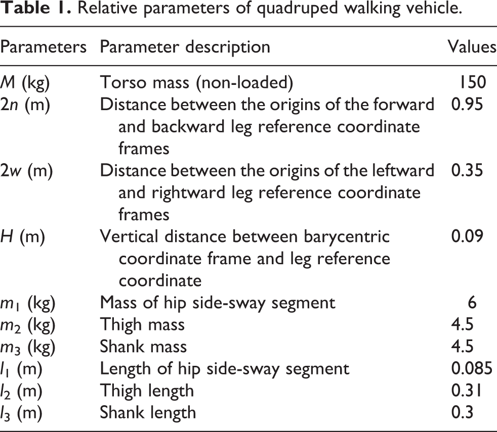
Relative parameters of quadruped walking vehicle.
Due to floating torso, the overall motion of the load-carrying quadruped vehicle is complex. Here, kinematic modeling is implemented, based on the six-dimensional space vector, as proposed by Featherstone. 17 First, the links and joints of the vehicle are numbered, starting at 1 for the vehicle torso, acting as the base of motion, while the ground is numbered as 0. Following the order of right-front leg, left-front leg, left-rear leg, and right-rear leg, the links of the walking vehicle are numbered from 2 to 13, respectively. Joint i (i ≥ 1) connects link i and i − 1 (Figure 2(a)). In addition, coordinates frames are established on links, to describe the motion of links, as shown in Figure 2(b).

(a) Numbering for links and joints and (b) coordinates frames of links.
The velocity of the quadruped walking vehicle’s links can be obtained by adding the velocity of adjacent links and the velocity of joints. Based on the reference, 17 we use carets to identify six-dimensional vectors. The single-joint model, as proposed by Roberson and Schwertassek, 18 is selected to describe the motion of adjacent links, as follows

where

where
The torso coordinates frame (coordinates frame 1) is chosen as the overall reference frame, where the kinematic analysis is carried out. Since the vehicle’s legs and torso are in series connection, while the legs are in parallel connection, the links speed and acceleration calculation for each leg is similar. This study only deals with the calculation of the links speed and acceleration on right-front leg, as shown in Table 2.
Calculation of links speed and acceleration of right-front leg.

The Jacobian matrices of legs play an important role in the trotting control of the walking vehicle. Here, the Jacobian matrix is calculated based on the space velocity recursion formula, described in equation (1), where the right-front leg is still taken as an example

where
CD modeling of quadruped walking vehicle
Prior art literature
19
shows that parameters of the centroidal dynamic equation for the walking vehicle can be calculated from parameters of the joints space dynamic equation. Hence, the joint space dynamic equation needs to be established first. The speed of the load-carrying quadruped walking vehicle can be described with

The joint space dynamic equation of load-carrying quadruped walking vehicle can be described in the form

where

Based on equation (6), in the vehicle torso coordinates frame, the dynamic equation of the walking vehicle can be established as

where

where

Based on the derivation of equation (9), the centroidal dynamic equation of the walking vehicle is obtained as

where
The walking vehicle’s torso weighs 150 kg and its single leg weighs 15 kg. Since the weight ratio between vehicle torso and a single leg is 10:1, the effect of leg motion on the vehicle motion can be ignored. Thus, the centroidal dynamic equation (10) of the load-carrying quadruped walking vehicle is modified as

where

where


where
Design of trotting gait controller for load-carrying quadruped walking vehicle
The VM control algorithm is a kind of task space control algorithm with good control performance and excellent robustness. However, the VM control method shortcomings have limited its application regarding cases of load-carrying quadruped walking vehicle with eccentric torso. In this section, a method of combining VM and CD is proposed to consider the effect of eccentric weight, when solving the resultant forces acting on a walking vehicle. The trotting gait controller for a load-carrying quadruped walking vehicle mainly consists of two parts: motion control of the torso and motion control of the swing leg.
Vehicle torso motion control based on VM and CD
1. Calculation of resultant forces acting on the walking vehicle
According to the CD, described in equation (10), calculation of the resultant forces, acting on the walking vehicle, can be divided into the calculation of expected acceleration
The torso acceleration

where α represents the roll angle of the walking vehicle, β represents the pitch angle,

Vehicle’s virtual components for every degree of freedom.
2. Optimal distribution of the resultant forces acting on the walking vehicle
The foot-end forces of supporting legs are of great importance to the steady walk motion of the vehicle. In the published literature, 21 the control method of Jacobian matrix orthogonal decomposition and the inverse dynamics was used to realize the LittleDog static gait walking. According to that approach, the joint moments are obtained without having to solve the foot-end forces. This method is simple in calculation and has a good control effect on small and light walking vehicles. However, in the case of heavy-weight load-carrying quadruped walking vehicles, consideration must be given to the acting forces between the supporting legs and the ground.
Combining the CD, described in equation (11), and the definition of equations (13) and (14), regarding parameters, the dynamic equation of the walking vehicle can be written, in barycentric coordinates frame, as follows

In equation (16), acting forces between the foot-ends and the ground remain unknown, therefore the resultant forces, acting on the walking vehicle, can be distributed to the supporting legs, through equation (16). In the known literature, 22,23 the distribution of virtual forces was studied in the case of a quadruped walking vehicle, controlled according to the VM method. It was pointed out that there was singularity in relation matrix, between virtual forces and foot-ends forces of supporting legs, while quadratic programming was used to achieve the optimal distribution of virtual forces. This article implements the method described in the prior art literature 22 for reference, to distribute the resultant forces to supporting legs.
An objective function is designed, to reduce internal forces at the foot-ends and achieve efficient walking


In equation (17),
The software package Gurobi is used to solve the quadratic programming of the above sequence, so as to realize the optimal distribution of the resultant forces, in real time. It ensures the stability and efficiency for the trotting gait of the walking vehicle.
3. Calculation of supporting leg joint torques:
After obtaining the forces acting between the supporting leg foot-ends and the ground, the Jacobian matrices can be used to calculate the torques of the supporting leg drive joints, as shown below
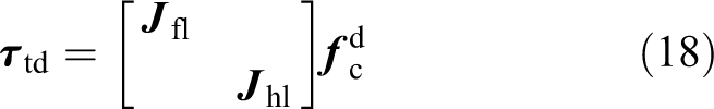
where
Swing leg motion control based on VM
The motion control of the swing leg is carried out in the vehicle torso coordinates frame. In order for the swing leg to adapt to some rough topography, a vertical falling phase is considered, at the end of swing phase. The leg foot-end swing trajectories are of the same form, in the forward direction and side direction, but the corresponding parameters have different values. Therefore, only the trajectories in x 1 and z 1 directions are given as follows


In equations (19) and (20),
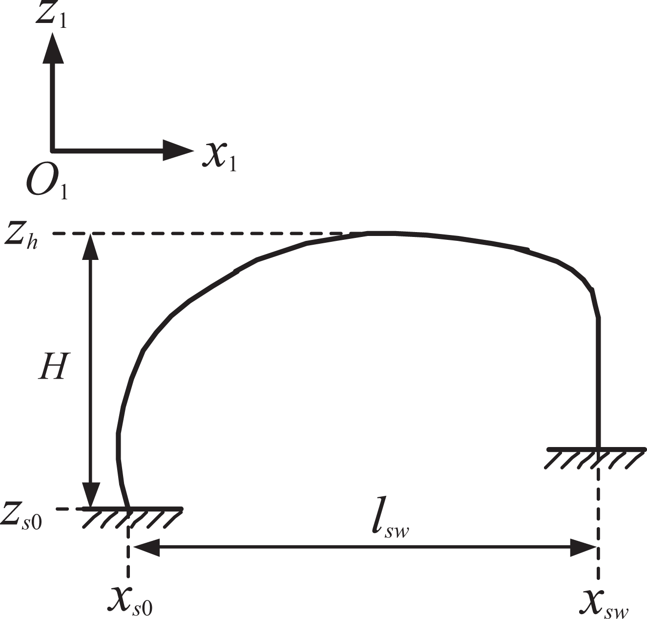
Sketch map of leg foot-end swing trajectory.
Based on the step length calculation method, in SLIP motion, the step lengths of the walking vehicle in forward direction lx and side direction ly can be expressed as


Virtual spring-damping components are added between the actual position of swing leg foot-end

where fsx
, fsy
, and fsz
represent the force applied to the swing leg foot-end in the directions of x
1, y
1, and z
1, respectively. (xsd
, ysd
, zsd
) and (

where
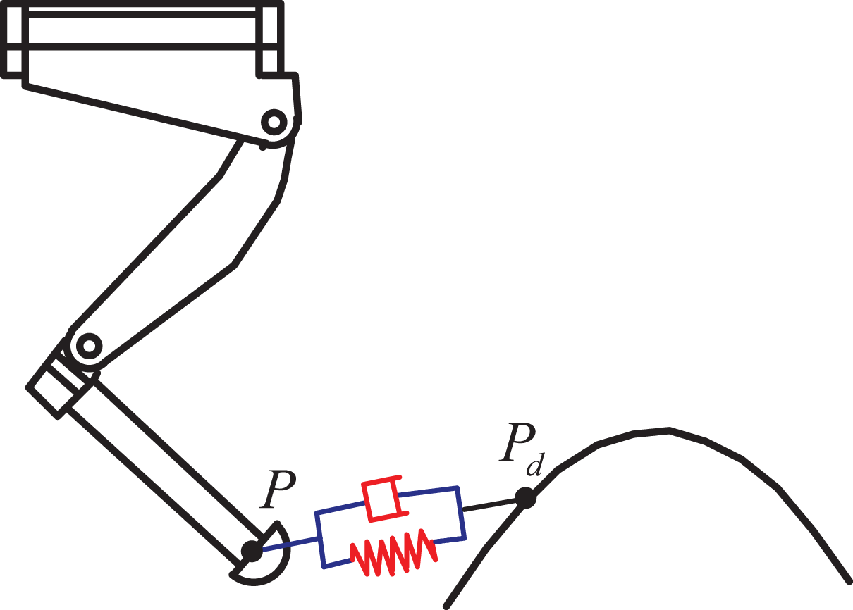
VM control of swing leg. VM: virtual model.
Trotting simulations of loading-carrying quadruped walking vehicle
A virtual prototype for load-carrying quadruped walking vehicle is established in Adams, while the control algorithm is set up in Simulink. The proposed control algorithm is verified by means of co-simulations. The torques, as calculated in Simulink, is transmitted to the joints of the simulation model in Adams, so as to force the walking vehicle to trot. The motion of load-carrying quadruped walking vehicle can be considered as a composition of forward and backward motion, leftward and rightward motion, and clockwise or anticlockwise rotation. Hence, in the verification process of the control algorithm, the expected velocity of the walking vehicle is considered the composition of the forward velocity (0.5 m s−1), the lateral velocity (0.05 m s−1), and the yaw rate (−0.15 rad s−1). Following, two cases are simulated, including the eccentric weight motionlessness, in relation to vehicle torso and the eccentric weight in motion, relative to vehicle torso. The simulations parameters are set as shown in table 3.
Simulation parameters setting.

Simulation of omnidirectional trotting gait for a vehicle with fixed eccentricity
The asymmetric arrangement of auxiliary components or load will easily cause fixed eccentricity in the vehicle. To verify that the presented control algorithm is effective in controlling trotting gait of the load-carrying quadruped walking vehicle, with fixed eccentricity, 30 kg of eccentric weight is added to the vehicle. The eccentric weight is fixed on the vehicle torso, while its barycenter coordinates, in the vehicle torso coordinate frame, are (−0.3, −0.1, 0.238). The VM control algorithm 22 and control algorithm presented in this article are used to force the walking vehicle to move omnidirectionally. The evolution of the vehicle parameters, in these two control algorithms, is shown in Figure 7. VM represents the VM control, and VM + CD represents the VM and CD control. Snapshots of the omnidirectional trotting gait is shown in Figure 6.

Snapshots of walking vehicle omnidirectionally trotting gait.
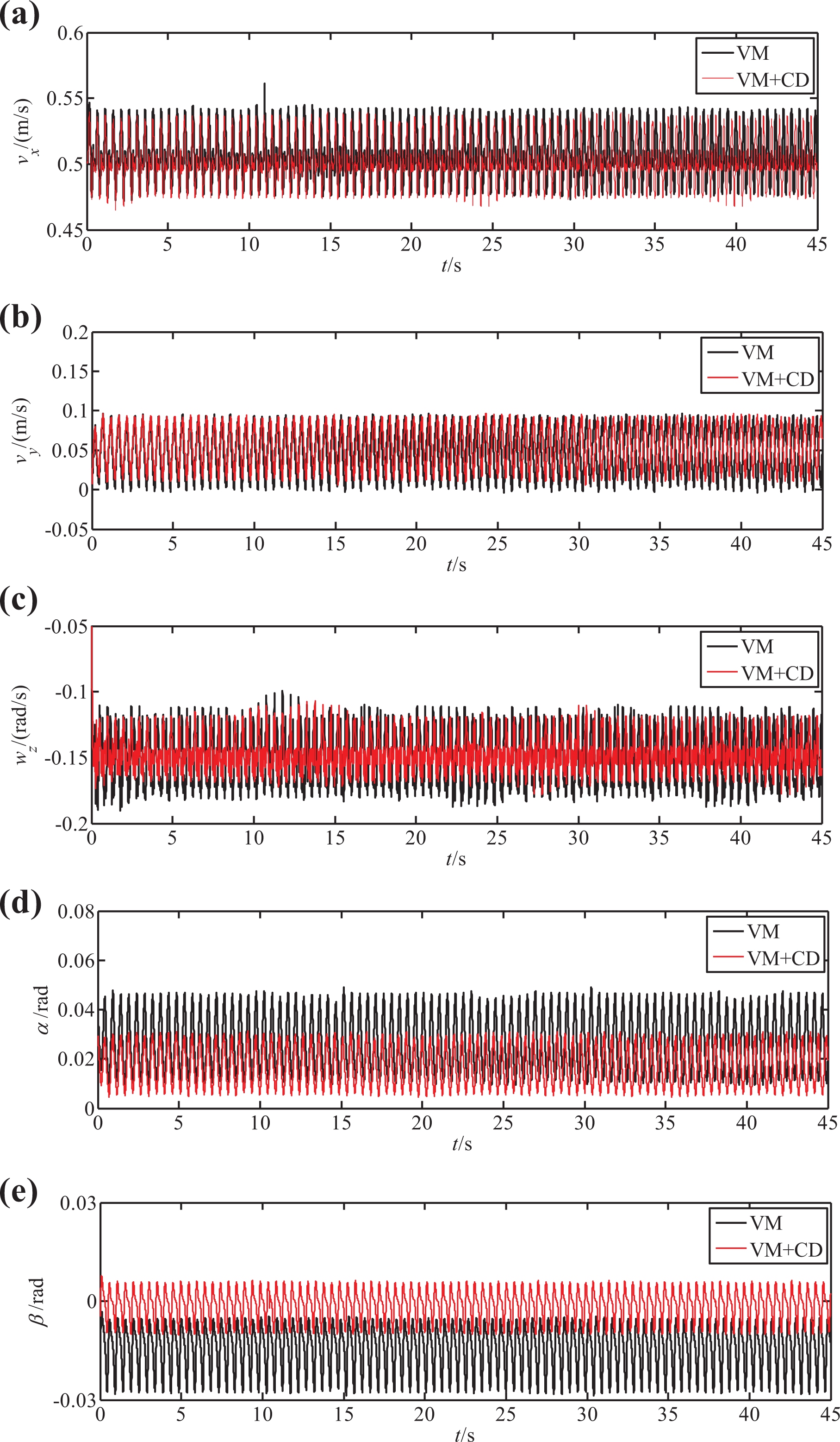
Variation curves of vehicle torso variables when torso is with fixed eccentricity. (a) Variation curve of forward velocity. (b) Variation curve of lateral velocity. (c) Variation curve of yaw rate. (d) Variation curve of roll angle. (e) Variation curve of pitch angle.
Figure 7 shows that both control methods have made the load-carrying quadruped walking vehicle (with fixed eccentricity) to walk omnidirectionally, but have produced different control effects. To compare the control results of the two methods more intuitively, the variation ranges and errors of the relevant parameters are given in Table 4. The errors are calculated as follows: we take the median of each parameter, then make a difference with the desired value, and calculate the absolute value.
Simulation results of the vehicle with fixed eccentricity.

VM: virtual model CD: centroidal dynamics.
In Figure 7(a) to (c) and Table 4, it is evident that the two control algorithms differ slightly, regarding the control effect of forward velocity, lateral velocity, and yaw rate. All three velocity values show periodical change, in the vicinity of the target value. Figure 7(d) and (e) shows that the two control algorithms differ significantly with regard to the control effect of the vehicle attitude angle. When the VM control algorithm is used, the error of roll angle is 0.03 rad and fluctuates from 0.01 rad to 0.045 rad, while the error of pitch angle is 0.018 rad and varies from −0.028 rad to −0.005 rad. Both roll angle and pitch angle apparently incline to the side with eccentric weight. When the VM and CD method is used on the walking vehicle, the errors of roll angle and pitch angle are 0.015 rad and 0.002 rad, respectively, while they vary from 0.005 rad to 0.03 rad and from −0.01 rad to 0.006 rad, respectively. Comparing to the VM control algorithm, the control algorithm, as presented in this article, has produced a roll angle error, reduced by about 50%, while the pitch angle error appears lower by about 89%. In addition, there is a smaller variation range. All these prove that this control algorithm is more effective in controlling the walking vehicle with fixed eccentricity. In the specific case under consideration, the eccentric weight is on the vehicle’s right rear leg side. Due to the structure of the vehicle, the pitch angle can be well compensated, but the roll angle compensation ability is limited.
Simulation of omnidirectional trotting gait for a vehicle with moving eccentricity
When the attachment between eccentric weight and walking vehicle becomes loose, the eccentric weight may move along with the vehicle torso, within the walking vehicle’s storage rack. Suppose that the eccentric weight changes its position in a forward and lateral direction. In the simulation, prismatic joints are added to the eccentric weight, in the forward and lateral direction of the vehicle torso, while translational motions are added to the prismatic joints, actively changing the position of the load. Suppose that the displacements of eccentric weight in the x- and y-directions of the vehicle torso coordinates frame are xf and yf , respectively. Both xf and yf change according to sine law and their cycle is identical to the vehicle’s gait cycle, as shown in Figure 8. The VM control algorithm and the control algorithm, discussed in this article, are used, respectively, to make the walking vehicle walk omnidirectionally, producing the results shown in Figure 9.
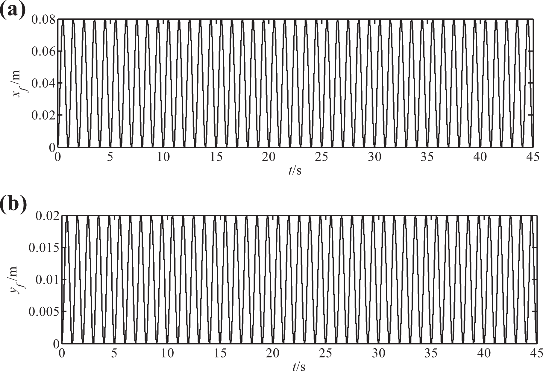
Displacement of eccentric weight. (a) Motion of eccentric weight in the x-direction. (b) Motion of eccentric weight in the y-direction.

Change of torso parameters in the omnidirectional motion of walking vehicle with moving eccentric weight. (a) Variation curve of forward velocity. (b) Variation curve of lateral velocity. (c) Variation curve of yaw rate. (d) Variation curve of roll angle. (e) Variation curve of pitch angle.
Figure 9 shows that both algorithms have made the walking vehicle move omnidirectionally, as the position of eccentric weight is changing, but their parameters changed according to different laws. The variation ranges and errors of the relevant parameters are given in Table 5. The calculation method of the errors is the same as that in the previous section.
Simulation results of the vehicle with moving eccentricity.

VM: virtual model CD: centroidal dynamics.
Figure 9(a) and (b) and Table 5 show that the two control algorithms differ slightly in the control effect of forward and lateral velocity. Both show periodical change, close to the target value. Figure 9(c) demonstrates that, in the two control methods, the yaw rates change around the target value. However, when the control algorithm, presented in this article, is used, the variation range of yaw rate is [−0.17, −0.11], whereas in the case of VM control algorithm, the variation range of yaw rate is [−0.2, −0.11]. The presented methods produce a smaller deviation between the yaw rate’s actual value and target value. Figure 9(d) and (e) shows that, when VM control method is used, the error of roll angle is 0.02 rad, while it varies from 0 rad to 0.07 rad. Accordingly, the error of pitch angle is 0.015 rad, while it varies from −0.035 rad to 0. When the presented control algorithm is used, the roll angle error is 0.01 rad, varying from 0 to 0.04 rad, while the pitch angle error is 0.003 rad, changing from −0.015 rad to 0.01 rad. Hence, when the VM and CD control method is used, the error of roll and pitch angle is reduced by about 50% and 80%, respectively, suggesting that the proposed control algorithm is effective, also in the case of a moving eccentric weight.
Conclusion
This article studies the control algorithm for the trotting gait of load-carrying quadruped walking vehicle with eccentric torso, dividing the control of the vehicle into the control of vehicle torso motion and the control of the swing leg motion. The combination of VM control and CD control is used on the motion of vehicle torso, while the VM control is used on the motion of the swing leg. The omnidirectional trotting of the load-carrying quadruped walking vehicle with eccentric torso is achieved, while the following conclusions are reached: Though VM control method can make the vehicle walk omnidirectionally, it is easily affected by eccentric weight, causing the vehicle’s attitude angle to deviate significantly from the target value. The combination of VM and CD control produces a much better effect than the VM control alone does, because it takes into consideration the eccentric weight in the control of the vehicle. The simulation parameters have great impact on the control results. Although different parameters will lead to differences in control effects, the results of the comparison between the two methods will not change. The characteristics of the physical prototype should be taken into account in the process of parameters selection. As a result, the parameters should not be too large or too small. Due to the vehicle structure, there is still some deviation between the roll angle’s actual value and the expected value, when the VM and CD control method is used. The control algorithm can reduce the influence of eccentric weight, only to some extent.
Limited by hardware conditions, such as hydraulically powered joints, appropriate experiments cannot be carried out, at present time. In the future, the control algorithm will gradually be applied to walking vehicles. It is considered that, in case of a large eccentric weight, a balance weight will be added to the vehicle torso, to make vehicle walk more steadily.
Footnotes
Declaration of conflicting interests
The author(s) declared no potential conflicts of interest with respect to the research, authorship, and/or publication of this article.
Funding
The author(s) disclosed receipt of the following financial support for the research, authorship, and/or publication of this article: This work was supported by the National Natural Science Foundation of China (grant no. 51305457).