
Abstract
With the introduction of the laterally bounded forces, the tilt-rotor gains more flexibility in the controller design. Typical feedback linearization methods utilize all the inputs in controlling this vehicle; the magnitudes as well as the directions of the thrusts are maneuvered simultaneously based on a unified control rule. Although several promising results indicate that these controllers may track the desired complicated trajectories, the tilting angles are required to change relatively fast or in large scale during the flight, which turns to be a challenge in application. The recent gait plan for a tilt-rotor may solve this problem; the tilting angles are fixed or vary in a predetermined pattern without being maneuvered by the control algorithm. Carefully avoiding the singular decoupling matrix, several attitudes can be tracked without changing the tilting angles frequently. While the position was not directly regulated in that research, which left the position-tracking still an open question. In this research, we elucidate the coupling relationship between the position and the attitude. Based on this, we design the position-tracking controller, adopting feedback linearization. A cat-trot gait is further designed for a tilt-rotor to track the reference; three types of references are designed for our tracking experiments: set point, uniform rectilinear motion, and uniform circular motion. The significant improvement with less steady state error is witnessed after equipping with our modified attitude–position decoupler. It is also found that the frequency of the cat-trot gait highly influenced the steady state error.
Introduction
Comparing with the conventional quadrotor, 1 –4 the tilt-rotors 5 –9 provide the lateral forces, which are not applicable to the collinear/coplanar platforms (e.g. conventional quadrotors). The additional mechanical structures (usually tilting motors) mounted on the arms of the tilt-rotor provide the possibility of changing the direction of each thrust or “tilting.” As a consequence, the number of inputs increases to eight (four magnitudes of the thrust and four directions of the thrusts).
One of the systematic methods to solve tracking problem for a conventional quadrotor is feedback linearization (dynamic inversion), which transfers the nonlinear system to a linear one applicable to implement the linear controllers. Hereon, each output of interest is manipulated individually. Since the number of the inputs in conventional quadrotors (four) is less than the number of degrees of freedom (six), a controller can independently stabilize four outputs at most. Typical choices of these four outputs can be attitude–altitude 10 –14 and position–yaw. 6,15 –18
On the contrary, since the number of inputs in Ryll’s tilt-rotors (eight) is larger than the number of degrees of freedom, the vehicle becomes an over-actuated system. This property intrigues the research on fully tracking the entire degrees of freedom; the tilt-rotor 7 not only tracks the desired time-specified position but also the desired attitude relying on the eight inputs. 19,20 Although the promising results yield acceptable tracking result, the tilting angles vary greatly or over-rapidly, which sharpens the feasibility of implementing the relevant controllers.
To solve this problem, our previous research 21 plans the gait of the tilt-rotor before applying feedback linearization. The tilting angles are assigned beforehand, rather than manipulated by a unified control rule. Hereby, the magnitudes of the thrusts are the only inputs.
However, several challenges may hinder the application of this method. One of them is the singular decoupling matrix 22 of feedback linearization. Considerable attention has been paid to this issue for the conventional quadrotor. 10,23 It has been proved that the decoupling matrix is always invertible for a tilt-rotor with an over-actuated control scenario. 7 However, this matrix may be singular if we take the magnitudes of the thrusts as the only inputs after the gait plan for a tilt-rotor. Further discussions on avoiding the singular decoupling matrix can refer to our previous work. 21
On the other hand, though the previous research
21
witnessed promising result in tracking attitude and altitude, the position
Similar to the gait plan problem in four-legged robots, 27 –29 we 21 proposed several gaits for a tilt-rotor, averting the singular decoupling matrix. However, the gait in that research 21 did not consider the gait patterns with varying tilting angles; all the gaits analyzed were the combinations of the fixed tilting angles. Another contribution of this research is to adopt the time-specified varying gait, which is inspired by cat trot. 30 –32
Three types of references are designed to track for a tilt-rotor in simulation (Simulink). Notable improvements in tracking result are witnessed after the application with our modified attitude–position decoupler.
The rest of the article is structured as follows: The second section briefs the dynamics of the tilt-rotor. The third section explores the relationship coupled in attitude and position in a tilt-rotor before proposing the modified attitude–position decoupler, which is further used to design a controller. The fourth section introduces a gait for a tilt-rotor which is inspired by a cat-trot gait. The discussions upon the stability of the relevant controller are addressed in the fifth section. The sixth section introduces the settings of the simulation tests, the results of which are displayed in the seventh section. Finally, we make conclusions and discussions in the eighth section.
Dynamics of the tilt-rotor
Figure 1
21
sketches Ryll’s tilt-rotor. This tilt-rotor
7,21
can adjust the direction of each thrust during the flight; tilting each arm changes the direction of the thrust, which is restricted in the relevant yellow plane in Figure 1.

The sketch of the tilt-rotor.
The position

where m is the total mass, g is the gravitational acceleration,

where

where
The angular velocity of the body with respect to its own frame,

where IB
is the matrix of moments of inertia, Km
(

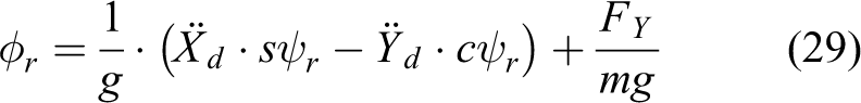
The relationship between the angular velocity of the body,

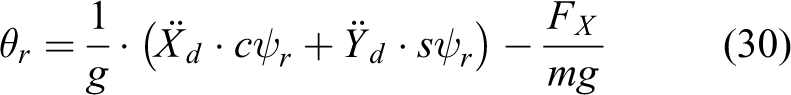
where “
We refer the readers to the literature 36,37 for the detail in modeling the coefficients of the thrust, drag moment, and inertia moment, IB . They are assumed to be constant in this research.
The parameters of this tilt-rotor are specified as follows:
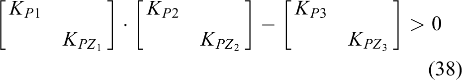
Attitude–position decoupler and feedback linearization
The controller for the tilt-rotor comprises three parts: modified attitude–position decoupler, feedback linearization, and high-order PD controller.
Scenario of the controller
As mentioned, this controller can only control four degrees of freedom independently at most. Noticing that picking position and yaw may introduce the singular decoupling matrix, 10,23 the independently controlled variables decided in this research are attitude and altitude. 11,12,20,25
The rest of the degrees of freedom (position

The control diagram.
After dealing with the coupling relationship in position and attitude, an animal-inspired gait is designed for the tilt-rotor, which is detailed in the “Cat-trot-inspired gait” section.
Finally, feedback linearization (“Feedback linearization” section) is applied to accommodate a linear controller (“Third-order PD controller” section).
Modified attitude–position decoupler
The relationship (conventional attitude–position decoupler) between attitude and position in a conventional quadrotor 10 –14,17,20,25,26,38 –40 is


This relationship is deduced by linearizing the dynamics of a conventional quadrotor near hovering. However, this attitude–position decoupler does not hold for the tilt-rotor if the tilting angles are not all zero. Proposition 1 gives the modified attitude–position decoupler for a tilt-rotor.
Proposition 1 (Modified attitude–position decoupler)
The attitude and the position of a tilt-rotor can be approximately decoupled as

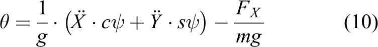
where FX and FY are defined by

Proof
Linearize equation (1) at the equilibrium states


Ignoring the high-order infinitesimal terms (e.g.
Formulas (12) and (13) guarantee the angular accelerations and the vertical acceleration of the tilt-rotor are zero, given the assumption of the attitudes in formula (14). The components of the thrust along X and Y, with respect to the body-fixed frame, are then calculated in formula (11) as FX and FY .
Remark 2
Given
Feedback linearization
The degrees of freedoms for the controller to track independently are attitude and altitude.
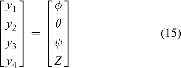
Define
Since

Assuming

calculating the third derivative of equation (18) 21 yields
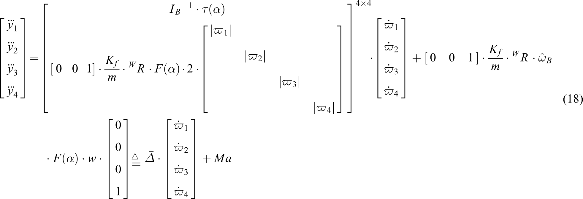
where
Observing equation (18), one receives the decoupled relationship in equation (19), compatible with the controller design process, which will be detailed in the “Third-order PD controller” section.

Obviously, it should be guaranteed that the decoupling matrix (
Proposition 2
When the roll angle and pitch angle of the tilt-rotor are close to zero, the decoupling matrix is invertible if and only if Condition (20) holds

where
Proof
See our previous research. 21
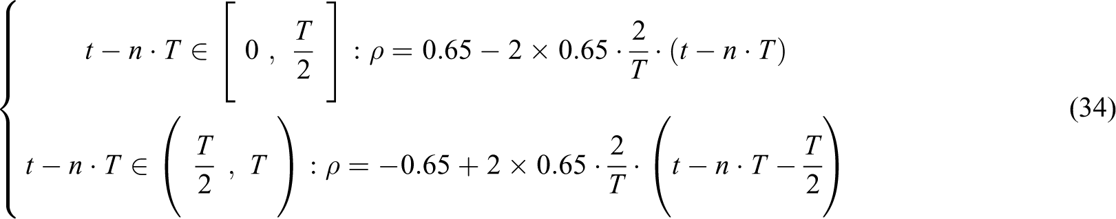
In this research, we adopt the cat-trot gait defined by


where
Proposition 3
When the roll angle and pitch angle of the tilt-rotor are close to zero, the cat-trot gait introduces no singular problem.
Proof
Substituting (21) to (24) into the left side of (20) yields

Since
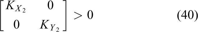
Third-order PD controller
Design the third-order PD controllers as


where
The control parameters in the above controller are specified as:
As for tracking the rest degrees of freedoms (
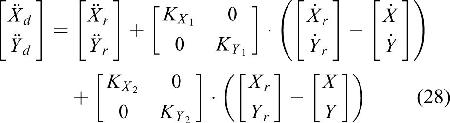
where
The output (left side) of this PD controller is the desired position, which will be transferred to the desired attitude by modified attitude–position decoupler,
where
Notice that the attitude–altitude controller in (26) is designed much faster than the position-tracking controller in (28); the control coefficients, K, are designed much larger in (26) than the ones in (28).
Cat-trot-inspired gait
This research adopts three different gaits (fixed tilting angles, cat trot with instant switch, and cat trot with continuous switch.
Fixed tilting angles
The gait with the fixed tilting angles is defined by


The tilting angles remains constant (
Cat trot with instant switch
Typical cat gaits can be categorized as walk gait, 30 trot gait, 31,32 and gallop gait. 31,32
Parallel to the trot gait of a cat, we plan the cat-trot-inspired gait, which is specified as

where
We compare the result in the simulations with different periods, T.
Cat trot with continuous switch
In the cat-trot gait with instant switch, the tilting angles change discretely. This section provides a continuous cat-trot gait
where
Also, we compare the result in the simulations with different periods, T.
Stability analysis
In this section, we address the discussion on the stability of our controller. Firstly, we provide the stability proof to our controller. Secondly, we make comments on the potential state errors.
Stability proof
Noticing that the singular decoupling matrix is avoided (see Proposition 3), the original nonlinear system is stable if the linearized system is proved stable, given that the constraints (e.g. non-negative constraints of the thrusts, upper bound of the thrusts, etc.) are not activated; advanced stability analyses are demanded if the constraints are activated. 41 In this research, these constraints are not activated, which simplifies our discussion on the stability.
Proposition 4 (Exponential stability of attitude and altitude)
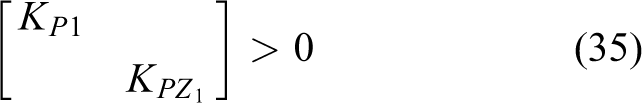
The attitude and altitude are exponentially stable if


Proof
Applying Hurwitz Criterion or Routh Criterion to (26) and (27) yields (35) to (38).
Proposition 5 (Exponential stability of position
)
The position

Proof
Applying Hurwitz Criterion or Routh Criterion to (28) yields (39) to (40).
Thus, all degrees of freedom have been proved exponentially stable.
Remarks to the stability proof
In the “Stability proof” section, we proved that the attitude and altitude are exponentially stable applying this controller, which has been verified by simulations.
21
However, the references in that study
21
were attitude and altitude. The position
Though the modified attitude–position decoupler in formulas (29) and (30) and the position-tracking controller in (28) may be used to track a position, proved in Proposition 4 and 5, there can be steady state error in position using this controller.
Remark 6 (Steady state error in position
for tilt-rotors)
There can be steady state error with the application of the controllers in (26) to (30). This is because that the modified attitude–position decoupler was deduced by linearization at the state defined in (12) to (14). However, the states in (12) to (14) may not be satisfied simultaneously; generating zero angular accelerations and vertical acceleration in (12) and (13) may only be possible for non-zero roll angles and pitch angles, indicating that the conditions in (14) are violated.
As the consequence, the system may be stabilized at a state near the state for linearization rather than on it. This unprecise relationship between the position and the attitude can introduce unexpected steady state error.
Figure 3 helps demonstrate the above discussions on the source of the steady state error. We linearize (green dash line) the dynamics of a tilt-rotor at the equilibrium for a conventional quadrotor (red point), where both the roll angle and pitch angle are zero. However, the real equilibrium for a tilt-rotor is at the blue point. The bias introduced in the linearization may produce the steady state error.

The linearization bias in the tilt-rotor.
Remark 7 (Steady state error in position
for conventional quadrotors)
There are no steady state errors in position
Figure 3 also helps demonstrate the reason why there are no steady state error for a conventional quadrotor. We linearize (green dash line) the dynamics of a quadrotor at the equilibrium for a conventional quadrotor (red point), where both the roll angle and pitch angle are zero. On the other hand, this state (red point) is exactly the quadrotor is supposed to be stabilized at.
Trajectory-tracking experiments
The tilt-rotor is expected to track three types of trajectories in our experiments. They are set point, uniform rectilinear motion, and uniform circular motion.
Set point
One may notice that our previous research
21
tracks the set point using the similar controller. However, the set point set in that work
21
is the attitude–altitude reference (e.g.
In modified attitude–position decoupler (Proposition 1), we explicit the relationship between the position
The set point reference designed in this experiment is position–yaw pair

Thus, the reference settings in formula (28) are
We track this set point adopting the gaits with the different fixed tilting angles
As discussed in Remark 6, the steady state error is taken to evaluate the result of each experiment. We compare the resulting steady state errors between the controller adopting the conventional attitude–position decoupler in formulas (7) and (8) and the controller adopting the modified attitude–position decoupler in Proposition 1 for each gait.
Uniform rectilinear motion
The thorough introductions on the cat gaits can be referred to specialized studies on cats,
30
–32
where cat-walk gait is typically adopted at the moving speed of 0.54–0.74 m/s,
30
cat-trot gait and cat-gallop gait are typically adopted at the moving speeds of
Referring to this, we pair our reference in (42) with the speed around
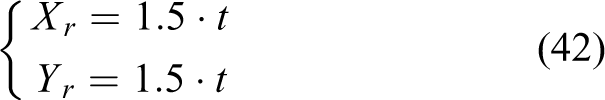
Besides formula (42), further reference settings in formula (28) are
Three different kinds of the gaits are analyzed: the fixed tilting angle gaits (
Also, the steady state error is taken to evaluate the result of each experiment. We compare the resulting steady state errors between the controller adopting the conventional attitude–position decoupler in formulas (7) and (8) and the controller adopting the modified attitude–position decoupler in Proposition 1 for each gait.
Uniform circular motion
A circular trajectory (uniform circular motion) is designed as


This indicate that the radius of the desired trajectory is 5 meters. The period is
Specially, besides formulas (43) and (44), further reference settings in formula (28) are
Same as the previous reference, three different kinds of the gaits are analyzed in this reference: the fixed tilting angle gaits (
Similarly, the steady state error is taken to evaluate the result of each experiment. We compare the resulting steady state errors between the controller adopting the conventional attitude–position decoupler in formulas (7) and (8) and the controller adopting the modified attitude–position decoupler in Proposition 1 for each gait.
Initial condition
The absolute value of each initial angular velocity of the propellers is 300 rad/s in all the simulations. This angular velocity is not sufficient to compensate the effect of the gravity and will cause unstable in attitude if maintaining this speed. The tilt-rotor is expected to track the desired trajectories (see sections “Set point”, “Uniform rectilinear motion,” and “Uniform circular motion”) relying on the controller designed in the “Attitude–position decoupler and feedback linearization” section, starting from this initial condition.
Results
This section displays the results of the tracking experiments with different references.
Set point
The set point are tracked by the gaits with the conventional attitude–position decoupler (marked as B in Figure 4) and with the modified attitude–position decoupler (marked as A in Figure 4).
The steady state errors along X and Y

The steady state errors.
Notice that the gait
Uniform rectilinear motion
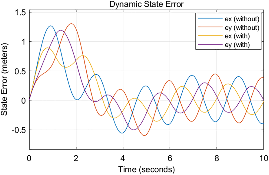
In tracking a uniform rectilinear motional reference defined in the “Uniform rectilinear motion” section, Figure 5 displays the resulting dynamic state errors,

The resulting dynamic state errors (constant tilting angles,
It can be clearly seen that the yellow curve, ex (with), and the purple curve, ey (with), are closer to zero comparing with the blue curve, ex (without), and the red curve, ey (without), respectively, after sufficient time. This indicates that the steady state errors are reduced after equipping with the modified attitude–position decoupler.
The tracking result (dynamic state errors) for the uniform rectilinear motional reference adopting the cat-trot gait with instant switch (

The resulting dynamic state errors, adopting the cat-trot gait with instant switch (
It can be concluded that the controller equipped with the modified attitude–position decoupler receives smaller supreme of the dynamic state errors, calculating from sufficient time; the maximums of the yellow and purple curves, calculating from sufficient time, are smaller than the maximums of the blue and red curves, respectively.
Figure 7 demonstrates the dynamic state errors for the uniform rectilinear motional reference adopting the cat-trot gait with continuous switch (
The resulting dynamic state errors, adopting the cat-trot gait with continuous switch (
The similar results can be concluded for the cat-trot gait with continuous switch (
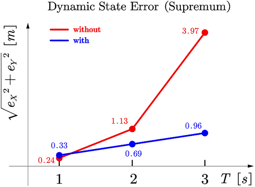
To compare the supremum of the dynamic state error,

Supremum of the dynamic state error,

Supremum of the dynamic state error,
The red curves in both figures represent the results of the supremum of the dynamic state error,
Clearly, with the increase of the period, the gait receives larger dynamic state error (supremum) for both cat-trot gaits with instant switch and with continuous switch.
The modified attitude–position decoupler significantly reduces the dynamic state error (supremum), especially for the gait with long period (e.g.
In addition, the dynamic state error (supremum) received by the cat-trot gait with continuous switch (Figure 9) is smaller than the corresponding dynamic state error (supremum) received by the cat-trot gait with instant switch (Figure 8), given the s period and type of the attitude–position decoupler.
Uniform circular motion
In tracking a uniform circular motional reference defined in the “Uniform circular motion” section, Figure 10 displays the resulting dynamic state errors,

The resulting dynamic state errors (constant tilting angles,
Similar results can be found that the yellow curve, ex (with), and the purple curve, ey (with), are closer to zero comparing with the blue curve, ex (without), and the red curve, ey (without), respectively, after sufficient time. This indicates that the steady state errors are reduced after equipping with the modified attitude–position decoupler.
The tracking result (dynamic state errors) for the uniform circular motional reference adopting the cat-trot gait with instant switch (

The resulting dynamic state errors, adopting the cat-trot gait with instant switch (
Similarly, the results show that the controller equipped with the modified attitude–position decoupler receives smaller supreme of the dynamic state errors, calculating from sufficient time; the maximums of the yellow and purple curves, calculating from sufficient time, are smaller than the maximums of the blue and red curves, respectively.
Figure 12 demonstrates the dynamic state errors for the uniform rectilinear motional reference adopting the cat-trot gait with continuous switch (

The resulting dynamic state errors, adopting the cat-trot gait with continuous switch (
Also, the similar results are concluded for the cat-trot gait with continuous switch (
Likewise, to compare the supremum of the dynamic state error,
Supremum of the dynamic state error,

Supremum of the dynamic state error,
The red curves in both figures represent the results of the supremum of the dynamic state error,
The similar results here show that, with the increase of the period, the gait receives larger dynamic state error (supremum) for both cat-trot gaits with instant switch and with continuous switch.
Also, the modified attitude–position decoupler significantly reduces the dynamic state error (supremum), especially for the gait with long period (e.g.
In addition, the dynamic state error (supremum) received by the cat-trot gait with continuous switch (Figure 14) is smaller than the corresponding dynamic state error (supremum) received by the cat-trot gait with instant switch (Figure 13), given the s period and type of the attitude–position decoupler.
Conclusions and discussions
The decoupling matrix is invertible in feedback linearization (attitude–altitude) for a tilt-rotor, adopting cat-trot gait. All the references considered in this research (set point, uniform rectilinear motion, uniform circular motion) are successfully tracked with acceptable steady state error by cat-trot gait.
The relationship between position and attitude of the tilt-rotor is elucidated. The modified attitude–position decoupler is invented for position-tracking problem for a tilt-rotor. It significantly reduces the dynamic state error (or steady state error for the point reference) comparing with the conventional attitude–position decoupler.
The length of the period of the cat-trot gait highly influences the dynamic state error in tracking a uniform rectilinear reference and a uniform circular reference. Specifically, a gait with a shorter period tends to receive a smaller supremum of the dynamic state error, calculating after sufficient time. On the other hand, the modified attitude–position decoupler notably reduces the dynamic state error for the cat-trot gait with a large period.
In general, the continuous cat-trot gait receives smaller supremum of the dynamic state error, calculating after sufficient time, than the discrete cat-trot gait, given same period and the type of the attitude–position decoupler.
There are several questions remaining to be answered further.
Firstly, equation (17) takes the tilting angles constant; they are assumed to be constant during the entire flight. While the switching process in the discrete gait and the entire period in the continuous gait violate this condition. Addressing the discussions on the underlying robustness is beyond the scope of this research, which can be a further step.
Secondly, though the steady state errors and the supremum of the dynamic state errors, calculating after sufficient time, are found reduced after applying the modified attitude–position decoupler, further reduction of the dynamic state error may be possible by not ignoring the high-order infinitesimal terms while deducing the modified attitude–position decoupler.
Also, analysis on other different cat gaits (e.g. gallop and walk) can be another further step for the gait plan for the tilt-rotor.
Footnotes
Declaration of conflicting interests
The author(s) declared no potential conflicts of interest with respect to the research, authorship, and/or publication of this article.
Funding
The author(s) received no financial support for the research, authorship, and/or publication of this article.