
Abstract
The energy storage efficiency is an important performance of a robot or a man–machine interaction device. This article will introduce the process of design and energy storage research of a variable stiffness elastic actuator with a two-elements and one actuator mod. Firstly, the principle model will be present to analyze the operation theory. Then, the simulation and experiment model will be described to calculate the characteristics of the device. The stiffness ratio of the two springs constituting the elastic element of the device will be studied in detail, and the results can present the rule of the energy storage value. Finally, the performance of the device, the error of the experiment, and a special mechanism which presented at the extreme shape condition of the ratio will be discussed. The conclusion is that the maximum energy that the device can store is 1.415 J at the stiffness ratio equaling 0.46, and the energy storage efficiency is 1.3608 at the ratio equaling 0.45, when the weight of the device is 3.54 kg and the apparent stiffness is about 3450 N/m.
Introduction
The ratio of the energy storage of an elastic element in a robot to the total amount of energy output of the actuator is the efficiency of energy storage (EOES), which is so important that it can significantly affect the motion capability of legged robots.
To increase the EOES of the robots, a variable stiffness elastic actuator (EA), realized by the variable length of linkage, has been designed by Visser and his team, 1,2 and the design theory of their mechanism has been verified with simulation and experiment. Brown has presented a passive-assist device, 3 –5 which consisted of actuator and elastic element, and introduced the optimization method of the spring and the results of the experiments to verify that EOES of the parallel elastic actuator (PEA) is higher than other mechanisms. Mazumdar has designed a robotic joint with PEA, 6 which increased the EOES, according to the motion data of the walking robotic joint. The main mechanisms of the research above are series elastic actuator (SEA) or PEA. On the other hand, the clutch EA and the multi-state elastic actuator (MEA) can present better EOES performance. Plooij and his team have designed a bidirectional clutched PEA, 7,8 which consisted of a differential mechanism and a bidirectional brake clutch, and the energy consumption has been reduced by 62%. Haufle et al. presented an electric clutch PEA, 9 which can reduce the energy cost by 80% and decrease the required moment by 2/3. Mathijssen has designed an MEA named +SPEA. 10,11 This device consisted of four serial elastic elements, which were parallel, and the dephased mutilated gears has designed to reduce the energy consumption.
These recent research works have achieved an amount of conclusion about the EOES of actuators that applied in robotics and machines with man–machine interaction, which can exalt the motion capability and the safety, and can reduce the energy consumption obviously. In addition, these have also provided the theory evidence and the future working importance, such as the EOES of an elastic actuator with variable stiffness (VSEA) that can be controlled in real time. An instance of the VSEA, the main direction of our research team recently, is shown as follows. If a spring is the elastic element of the device, the variable stiffness could be realized by adjusting the spring length that is proportional to the stiffness of the spring, and the variable length of the spring could be realized by motor, hydro-cylinder, or any other actuators.
To describe our research work in detail, a premised model should be present in this paragraph. From the recent research above, most EA devices contain one or more EA mods. This EA mod, with one execution end, is constituted with one elastic element and one connection mechanism, or one elastic element only. These EA mods are connected to each other in parallel in one EA device with one fixed end and one execution end. To introduce conveniently, these EA mods and devices could be named as OE mod (one elastic element mod), OOE device (one OE mod device), and MOE device (more OE mod device). This model is shown in Figure 1.

OE mod, OOE and MOE device, and TE mod. (a) is the schematic drawing of the OE mod, and the two arc lines in the OE mod separately mean that the actuator is connected to the elastic element directly or with the mechanism; (b) is the schematic drawing of the OOE device and the MOE device; (c) is the schematic drawing of the TE mod. OE: one elastic element; OOE: one OE; MOE: more OE; TE: two elastic elements.
Considering the OE device, the actuator should supply the energy to actuate the machine, and the variable stiffness should be realized with the mechanism. It is obviously that the change rule of the stiffness is simple and invariable with only one connection mechanism. Considering the MOE device, different elastic elements are connected to different mechanisms. Therefore, the change law of the apparent stiffness is complex and abundant, but it is still invariable. According to the recent research achievements, increasing the number of the actuator can control the stiffness change in real time, and the change law of the stiffness is variable. However, more actuators means more energy source and more complex control strategy. Therefore, it is necessary to present a different EA device to realize the variable change law of the apparent stiffness with not increasing the number of actuator.
On the bionic aspect, most creatures have their own special actuator devices, which are constituted by muscles and tendons. Taking human for example, the back muscle of the lower leg, which provide power for running and jumping, is constituted by soleus muscle and gastrocnemius muscle (as shown in Figure 2(a)). The gastrocnemius muscle connects the Achilles tendon to the femur, and the soleus connects the Achilles tendon to the tibia. These two kinds of muscle get energy and motion signal from mitochondria and nerve, respectively. Assuming the muscles as the actuators of a mod, the Achilles tendon can be considered as a spring (as shown in Figure 2(b)). The foot can be considered as the fixed end of a device, and the tibia and the femur can be considered as the execution ends. This EA device, mimics human calf muscle, contains one special EA mod, which is constituted by one spring and two actuators, and it has one fixed end, the foot, and two execution ends, the tibia and the femur. However, this special EA mod cannot be used in robotic or other machines immediately, because there are two coupled actuators, which cause complex control strategy.

The back muscle of the lower leg of human. (a) is the human muscle; (b) is the schematic diagram of equivalent mechanism structure.
The stiffness of the spring shown in Figure 2(b) is variable, since the tendon stiffness is variable. Therefore, on the engineering aspect, this spring could be regarded as two coupled springs, because the apparent stiffness of the device can be adjusted with changing the preload of one spring (as shown in Figure 3(a)). In addition, the motion and energy storage of the Ankle are mainly determined with the deformations of the femur tendon and the tibia tendon, and the characteristic of the knee is not determined with the tendons and the muscles of the lower leg but the muscles of the thigh, which is not the research focus in this article. Hence, the knee joint could be considered to be fixed, and the gastrocnemius muscle could be ignored (as shown in Figure 3(b)).

The engineering analysis of the back muscle of human lower leg. (a) is the equivalent schematic diagram of Figure 2(b); (b) is the schematic diagram omitting the gastrocnemius muscle.
Therefore, an innovative VSEA device, constituted by TE (two elastic elements) mod, as shown in Figure 1(c), can be presented, and it can be named as TE-VSEA. The energy storage performance of this device will be studied in this article.
Finally, the actuator of the TE-VSEA device is a hydro-cylinder, because the hydraulic system can supply more energy and more force, and its motion and force property are easy to analyze and calculate. The research content of this article about the innovative VSEA device will be described as follows: establish the basic physical model of the device and explain how it works; perform dynamic analysis of the device and establish the simulation models and the experimental models; perform example calculations and analyze the result; conduct experiments and verify the correctness of the theory.
Physical principle model
In this section, the physical model of the TE-VSEA will be explained in detail. First of all, we will introduce the components of the TE-VSEA and how they connected with each other. Then, the operating principle, especially the static characteristics of the springs and the motion of the locking mechanism, will be described. Finally, the reason of why we choose this kind of mechanism to study the EOES will be presented on the engineering aspect.
Components of the TE-VSEA
To reduce the complexity of the model and the duration of the experiment designing, the rotational motion of each components, as shown in Figures 2 and 3, is transformed into linear motion, and the components in the physical model should be vertical distribution, since the TE-VSEA described in this article will be used in legged robotics. The schematic of the TE-VSEA is shown in Figure 4. The mechanical structure in this figure is not the final design of the TE-VSEA, but a diagram to explain the working principle.

Physical principle model of the TE-VSEA. The load II and the execution end II are not existing in Figure 1(c) and Figure 3, but they are necessary, since the mass of the locking mechanism and the connection structure cannot be ignored.
This device contains two springs, one hydro-cylinder, two loads, and one locking mechanism. The spring I corresponds to the femur tendon (as shown in Figure 3(a)), and the spring II corresponds to the tibia tendon. The hydro-cylinder could be considered as the soleus muscle, which supply the energy and control signal. The top end of the hydro-cylinder actuator is connected with the load I, and the bottom end is connected with the load II, which connects the serial spring II to the locking mechanism. The parallel spring I connects the fixed end to the execution end I, which is contact with the ground but not fixed. The virtual chain consisted of the hydro-cylinder, the execution end, and the spring II is serial, and the relation between the hydro-cylinder and the spring I is parallel.
When the locking mechanism is unlocked, the load II can perform vertical motion relative to the fixed end, and both the spring I and II can deform. When the locking mechanism is locked, only the top end of the spring I can deform.
Motion of the loads
In the TE-VSEA, the load I is the external execution part which is the main object of energy exchange between the device and external environment, and the load II is the internal execution part which affects the movement of centroid and the energy flow of the entire device. Therefore, it is necessary to present the expression of their motion. Without considering the locking mechanism, the displacement of the loads can be written as follows

where y 1 and y 2 is the displacement of the loads I and II; ΔyS ,1 and ΔyS ,2 is the deformation of the springs I and II, respectively, and ya is the piston position of the hydro-cylinder.
The springs and the hydro-cylinder
The springs are used in almost every EAs that contain one or more springs, and the elastic potential energy storage is realized with the deformation of the springs. In the TE-VSEA, there are two springs connected with two execution ends, and the displacement of the top end of the spring I is variable, which affects the apparent stiffness of the entire device. Hence, the operating principle of the springs should be discussed from two aspects.
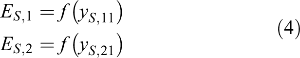
Firstly, considering each spring separately, the function of potential energy storage of the springs could be written as

where ES , i is the energy storage of the springs, and the expressions of the springs deformation could be given by

where yS ,11 and yS ,12 are the top end position and the bottom end position of the spring I, and yS ,21 and yS ,22 are the top end position and the bottom end position of the spring II.
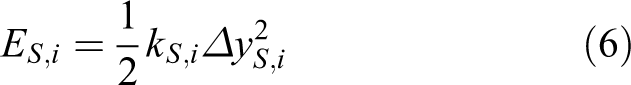
According to the model of the TE-VSEA, the bottom end of each spring is connected with the fixed end of the device, which is in contact with the ground. That means yS ,12 = 0, yS ,22 = 0, ΔyS ,1 = yS ,11, and ΔyS ,2 = yS ,21. Therefore, the function of energy storage is also equal to
The force of each spring is a function of the deformation and also is a function of the energy storage. Hence, the expression of the force is written as

and the energy storage function is equal to
The entire energy storage is given by

Secondly, considering the entire of the device, when the hydro-cylinder is disabled, the relation between the two springs is parallel. Therefore, according to equations (5), (6), and (7), the apparent stiffness, the force, and the energy storage can be written as follows

However, when the hydro-cylinder is enabled, the preload of the spring I is variable, since the position of its top end can be adjusted by the cylinder. Therefore, the apparent stiffness of the spring is variable because of the adjustable length of the spring I, and the apparent stiffness is a function of the motion of the cylinder. In this case, if the preload of the spring I is FS ,1, p , the stiffness of the spring I kS ,1, a and the stiffness of the entire device kS , a is given by

According to equations (5), (6), and (7), the apparent stiffness, the force, and the energy storage are equal to

The following description will be performed with the hydro-cylinder enabled, which is normal during the TE-VSEA operation.
The locking mechanism
There is one locking mechanism at the bottom of the spring I, and the operation mode can be switched to storing or locking by adjusting the angular rotation of the steering engine.
First, when the locking mechanism is enabled, the load II is fixed with the fixed end, and the spring cannot be deformed. In this case, the TE-VSEA could be considered as a PEA. Therefore, the apparent stiffness, the force, and the energy storage of the device are equal to
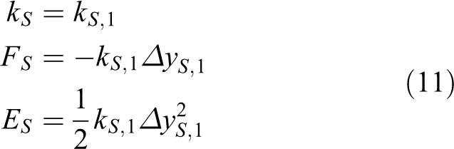
Second, when the locking mechanism is disabled, the apparent stiffness, the force, and the energy storage of the static model is the same as equation (10).
The dynamics model of the device could be considered as a two-degree-of-freedom forced vibration model, and it will be discussed in the dynamics analysis part of the third section.
On the engineering aspect, the stiffness of the spring I can be adjusted with the motion of its top end. The bottom end of this spring, which connected with the bottom end of the spring II and the fixed end, mainly realizes the function of energy storage. Comparing with the mod presented in Figure 1(c), there is not any mechanism between the actuator and the spring I, and the piston is connected to the spring II with a mechanism. Obviously, it is a typical TE mod, and the stiffness adjusting and the energy storing are realized with the hydro-cylinder. The friction in this model can be ignored, since all the components in this special TE mod are moving on the vertical direction, and the theoretical pressure on the horizontal direction is zero. Therefore, we choose this especial TE-VSEA to study the energy storage performance.
However, it is obviously that the top end and the bottom end of the spring I belong to one spring, and the coupling properties between them should be discussed. In addition, the dynamic analysis of variable stiffness and specific control process of the device are necessary either. These studies will be described in detail in another paper of our group.
Mechanical design and experimental models
To establish the simulation and the physical models, it is necessary to describe the mechanical structure at the beginning of this section. Then, the simulation model should be presented and analyzed to explain the process of energy store on the dynamic aspect. The entire experimental physical model will be described in the subsection “Experimental device.”
Mechanical design
The overall structure of the TE-VSEA is shown in Figure 5. In the TE-VSEA, the hydro-cylinder is the energy and the control signal source, the springs is the energy storage components, and the locking mechanism is the motion switching mod. In addition, at the beginning of the experiment, the device should be released at a special situation, which is that the fixed end is in contact with the ground and both springs are unforced, so that the energy converted from the gravitational potential energy to the elastic potential energy could be calculated conveniently. Hence, a suspension structure set on the top of the device is needed. Therefore, there are four important parts in the mechanical structure, the type of the springs, the installation structure of the cylinder and the springs, the locking mechanism, and the suspension structure.

The overall structure of the TE-VSEA. The parts constituting the load I, the load II and the fixed end are represented by three different colors. The spring I and the spring II are represented by black.
From the Figure 4, the gravity is opposite to the direction of the y-axis. During the process of energy storing, ΔxS , i is decreasing and ES , i is creasing. Therefore, the compression springs are better than the extension springs, since the normal deformation direction of the springs is in accordance with the movement direction of rigid bodies. However, the connection structure of compression spring is more complicated, especially at the location of the spring II. Based on these reasons, we choose the extension spring as the spring II, and the schematic drawing of the model structure is shown in Figure 5. Comparing with Figure 4, the only difference is the locations of yS ,21 and yS ,22. The installation structure of cylinder is simple, so that it is no need to explain in detail.
The suspension structure consisted of one electromagnet, one heat sink, one magnetic slider, and a small spring used to pull the slider (as shown in Figure 5). When the electromagnet is enabled, the slider is contact tightly with the electromagnet, and the hook holds the slider to hoist the entire device. When the electromagnet is disabled, the slider is separated from the electromagnet, and the device is released.
The schematic drawing of the locking mechanism is shown in Figure 6, since Figure 5 is not clear enough to explain the structure. The locking mechanism consisted of one pawl, one spinous axis, one sliding mount and two slide axes, and a small spring used to pull the pawl. The driver of the mechanism is a steering engine, which is hinged with the sliding mount with a linkage. When the steering wheel moves clockwise, the sliding mount moves to the right, and the mechanism is locked. When the steering wheel moves anticlockwise, the sliding mount moves to the left, and the mechanism is unlocked.

The schematic drawing of the locking mechanism.
In the schematic drawing of the final design (Figure 5), the top end of the spring I, the top slide axis, the main load, and the casing of the hydro-cylinder are fixed together. The piston of the hydro-cylinder, the sleeve, and the bottom end of the spring II are fixed together. The bottom end of the spring I, the bottom slide axis, and the top end of the spring II are fixed together. The bottom slide axis contacted with the ground is the fixed end of the device. The assembly of all the components fixed with the sleeve is the load II shown in Figure 4, and the assembly of all the components fixed with the main load is the load I.
Simulation model
Before the analysis of the force of the loads, it is necessary to determine the ratio of the spring stiffness, since the ratio affects real-time force even if the apparent stiffness is constant. If the sum of the stiffness is k, the ratio could be written as λ = kS ,1/k, and the stiffness of each spring can be given by
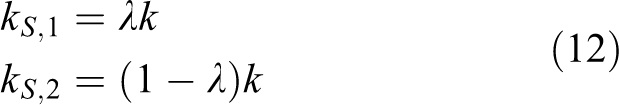
where 0 ≤ λ ≤ 1. Obviously, the device is an SEA if λ = 0, and it is a PEA if λ = 1 and the locking mechanism is locked (kS ,2 = ∞). That means the TE-VSEA can be transmute to other EA by changing kS ,1 and kS ,2.
The diagram of the force of the loads I and II is presented in Figure 7.
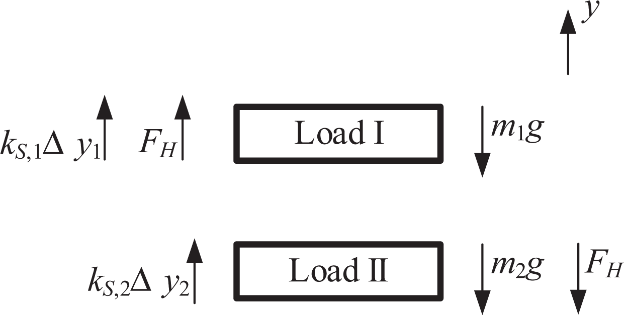
The diagram of the force of the loads I and II. FH is the force of the hydro-cylinder; m 1 and m 2 are the masses of the loads I and II.
The Coulomb friction on the contact surface between different parts is not important in this device, since the motion is on the gravity direction, and the pressure on the horizontal direction is 0. However, the damping of the springs, which affect the motion performance, should be considered in the simulation model. According to the second law of Newton, the expression of force of the loads I and II could be written as

where l 10 and l 20 are the nature length of the springs I and II, and dS ,1 and dS ,2 are the damping of them. Equation (13) could be rewritten as

According to equations (1) and (12), equation (14) could be rewritten as a second-order differential equation, and the numerical solution can be obtained by ODE45 method in MATLAB.
Experiment device
According to the suspension structure described in subsection “Mechanical design,” a bracket should be set in the experiment device to hold the TE-VSEA, and it should be assembled on a frame. The structure of the entire experiment device is shown in Figure 8(a), and the details of the suspension part and the locking mechanism are shown in Figure 8(b) and (c).

The mechanical structure of the experimental device. (a) is the actual structure of the TE-VSEA device; (b) is the structure of the suspension mechanism; (c), (d) and (e) are the locking mechanism structure under different viewing angles.
To decrease the weight of the device and the cost of the time of designing and producing, most of the parts are made with a 3-D printer. However, the pawl, the top slide axis, and the bottom slide axis are made of metal, since they have to support great force during the movement. The other parts are purchased, such as the pressure sensor, the electromagnet, and the steering engine.
Measuring the weight of the loads and the stiffness of the springs is necessary, because the result of calculation is inaccurate. The weights of loads I and II are 2.993 kg and 0.547 kg, respectively, and the sum of the stiffness of the springs is about 3450 N/m with a measurement error ±(60–80)N/m. The value of λ will be discussed in the fourth section.
The hydraulic system supports power for the device. It mainly contains a proportional flow valve, an accumulator, a relief valve, and a hydraulic power assembly, which consisted of an AC motor and a pump. The hardware of the control system mainly consisted of the central control PCB with an STM32F103RC chip, a Bluetooth serial port mod, and a number of power amplifiers. The power source of the electromagnet and the proportional flow valve is a 24 V DC power supply, and the electric source of the control system is an 18 V DC power supply. The photos of the hydraulic system, the control hardware, and the power source are shown in Figure 9(a), and the schematic diagram of the control system is shown in Figure 9(b).
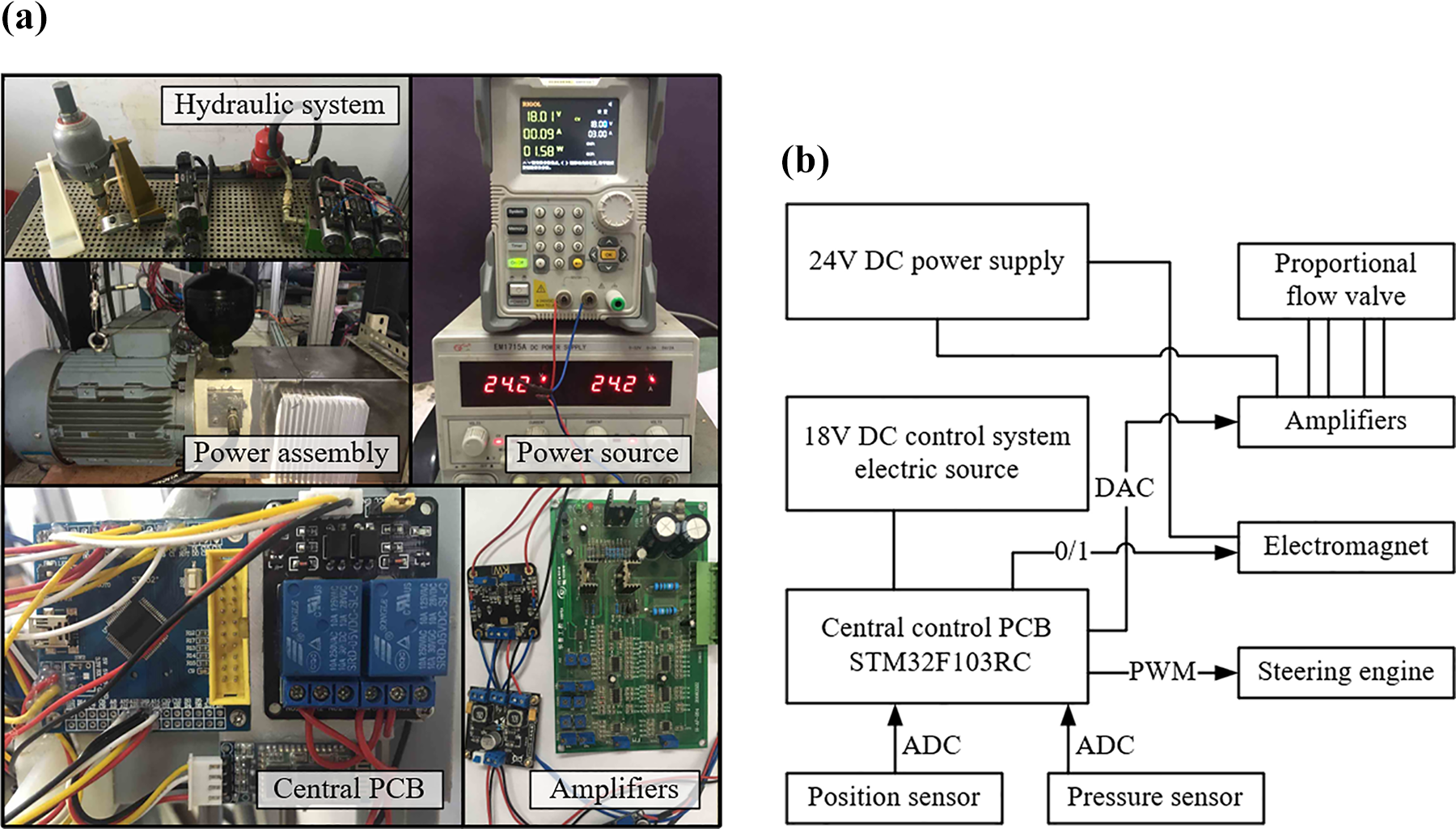
The control system of the experimental device. (a) is the photos of the hydraulic system, the control hardware, and the power source; (b) is the schematic diagram of the control system. The symbol “0/1” in (b) means the electromagnet is controlled with an electric relay.
The studies of the hydraulic system dynamics and the control strategy will be described in another paper of our organization.
Calculation and analysis of the model
The simulation model described above will be used to calculate the motion performance of the TE-VSEA device on theory in this section. In addition, the results of the experiment will be compared with the data of the calculation, and the energy storage efficiency, another importance of this article, will be discussed.
Calculation of the simulation model
In the third section, the weight of the loads and the stiffness of the springs have been measured. There are still some parameters should be listed, such as the piston stroke ΔyH , max, the cylinder max length lH , max, the nature length (l 10, l 20), and the damping (dS ,1, dS ,2) of the springs. These parameters are listed in Table 1.
The parameters of the model.

a The value of the sum of the spring stiffness is about 3450 N/m, since there is a measure error ±(60–80)N/m of the measurement equipment.
According to Table 1, the initial value of the second-order differential equation could be determined as follows

The process of solution is started at λ(0) = 0, Δλ = 0.01, and λ(i+1) = λ(i)+ Δλ. The boundary condition is y 2(i) ≥ 0, since the y value of the top end of the spring II cannot be negative. The flow-process diagram is shown in Figure 10.

The flow-process diagram of the solution.
Another importance of the solution process is yH , which is the motion function of the piston. It is not a calculation result, but a given function. Assuming that, the motion function is a quarter of sinusoidal function, the step size of ODE45 is Δt = 0.001 s, and the duration is td = 0.1 s, the motion function can be written as

and the velocity and the acceleration are the first derivative and the second derivative of yH , respectively.
To calculate conveniently, the sum of stiffness could be determined as 3450 N/m. According to equations (14), (15), and (16), the motion curve of the loads can be acquired, and the performance of the force and the energy can be obtained with equations (10) and (13).
According to Figure 11, there is an inflection point at time = 0.1 s, since the locking mechanism is enabled at this time, and the piston is moving according to the curve described with (16) at the left of the vertical dotted line, and it is stillness at the right. The left part of the curve λ = 0 is depressed, since the piston is moving so fast that the load II is going up in the beginning of the motion, and the stiffness of the parallel spring is 0 so that there is no parallel energy storing element to save the mechanical power. The left part of the curve λ = 1 is convex, since the stiffness of the spring II is 0, and the enabled time of the locking mechanism is later than the maximum energy storage time. The right part of each curve is the value of energy storage after locking mechanism enabled, and these values follow the rule of increasing first and then decreasing in the process of λ from 0 to 1, which is shown in Figure 12.

The sum of the energy storage of springs.

The relation between energy storage and λ.
The maximum value of the energy storage is 1.4165 J as the value of λ is 0.46 (as shown in Figure 12). The force of the hydro-cylinder can be calculated with equation (13), and the energy supplied can be obtained with

where EH is the energy supplied by cylinder during the initial time to the current moment.
According to Figure 13, the values of energy supplied at every moment are different, since the output energy of hydro-actuator depends mainly on the load of the piston. Different λ leads to different real time stiffness, which causes different loads of the piston, even if the masses of the loads I and II are not changed, and the apparent stiffness is constant. Hence, a simple comparison of the values of the energy supplied and the energy storage could not describe the performance of energy storage clearly.

The energy supplied by the hydro-cylinder.
The values of Figure 14 is obtained with Ed = ES − EH , where Ed is the difference between the energy storage of the springs and the energy supplied by the cylinder. The left parts of these curves are depressed, since the energy supplied with hydro-system is first converted to the kinetic energy of the loads and then converted to the elastic potential energy of the springs. The right parts of the curves present that the potential energy of the springs contain the gravitational potential energy change of the loads, expressed as ΔEG , because of the positive values.

The difference between energy storage and supplied.
In the ideal system without collision energy loss, ΔEG equals to Ed . However, no collision energy loss is impossible in the experiment, and the energy loss is hard to measure or calculate. In addition, with different λ, the loads are not changed, the sums of the stiffness are equivalent, and the motion functions of the piston are the same. Therefore, ΔEG do not affect the comparison of EOESs with different λ, and it is not necessary to subtract ΔEG from Ed , since ΔEG with different λ are equal at the end of energy storage. The EOES at the end of energy storage, which is defined as

could be calculated, and the curve of the relation between λ and η EOES is shown in Figure 15.

The relation between EOES and λ. EOES: efficiency of energy storage.
Form the calculation and analyze of simulation model, the max value of energy storage and the max ratio of EOES are existed at the λ = 0.46 and λ = 0.45, respectively (as shown in Figures 12 and 15).
This result is obtained from the fact that the sum of loads is constant and the apparent stiffness of the system is unchanged. More generally, EOES with different apparent stiffness will be discussed in the fifth section.
Analysis of the experiment
The stiffness of the springs, calculated with the empirical formula, is inaccurate, since the difference of the elements percentage in the material and the difference of the production processes may affect the stiffness of the products. Therefore, we have only prepared four pairs of springs for the experiment, and the stiffness sum of each pair is about 3450 N/m. The ratio values λ are 0.1429, 0.2076, 0.5768, and 0.7126.
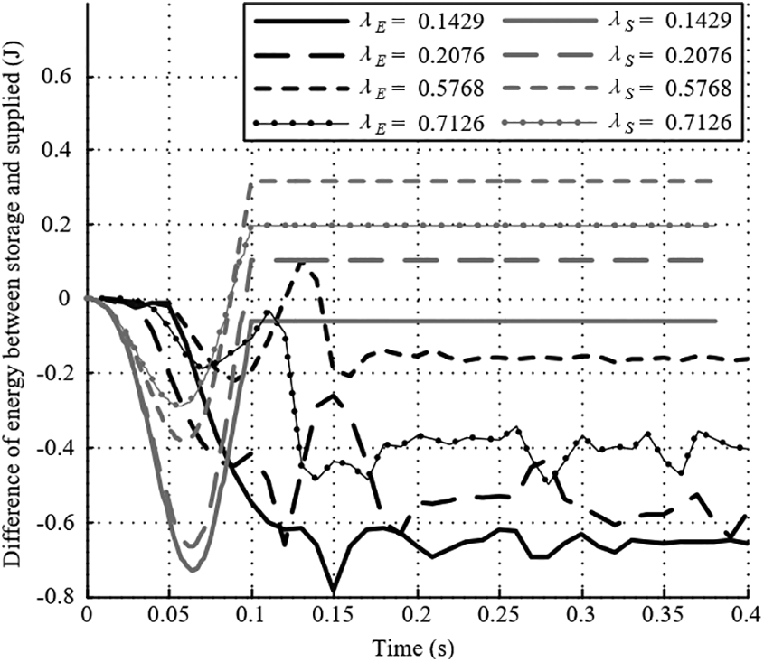
Because of the vibration of the device in the vertical direction, the curves after the locking time are unsmooth, and it is hard to analyze the relation between EOES and λ, as shown in Figure 12 or 15. However, describing EOES with the energy source and supplied diagram is clear enough to explain the relation between EOES and λ.
Neglecting the vibration of the system, the energy storage obtained from the experiment after the locking time approximately to the calculated values is shown in Figure 16, and the max energy storage value equals to 1.415 J. The small difference between the theory and the practice is caused by the inaccurate spring stiffness.

The sum of energy storage of the springs in experiment and simulation. λE and λS in the legend are the ratio of the experiment springs and the ratio of the simulation springs, respectively.
According to Figures 17 and 18, the experiment results are much lower than the simulation, but the variation trends of the energy storage and EOES with different λ are similar to the theory. In more detail, the experiment EOES with λE = 0.5768 is larger than other situations, and this λE is closer to the simulation λS = 0.46 than the others. The max average EOES equals to 0.8984.
The difference between energy storage and supplied in experiment and simulation.

The EOES of the experiment and simulation. EOES: efficiency of energy storage.
Discussion
In this article, a biomimetic TE-VSEA has been presented, and the differences of the energy storage characteristic with different λ have been studied. In this section, the performance of the device will be discussed, and the hydro-system energy consumption, the influence of apparent stiffness on EOES, and the error of experimental results will be explained.
Performance and a special situation
According to the simulation results, the maximum value of energy storage is 1.4165 J in the condition of λ = 0.46, and the minimum value is 0.2359 J in the case of λ = 0. As mentioned in the subsection “Simulation model”, the device transforms to an SEA if λ = 0, and the result explains that the increment of the energy storage between TE-VSEA at λ = 0.46 and SEA with equally apparent stiffness is 1.1806 J. When λ = 1, if the stiffness of the spring II is ∞, the device is a PEA, but this does not conform to the description of the simulation. There is another special situation shown in Figure 19 if λ = 1 and kS ,2 = 0.

The special device when λ = 1 and kS ,2 = 0.
This special device is very interesting that it is a PEA if the locking mechanism is enabled, and it is more like an SEA on the connection type between the actuator and the spring, when the locking mechanism is unlocked. However, the connection type of this SEA is contrary to the ordinary SEA, and the energy flow process of them are different. In this situation, the energy storage is 0.7549 J which is bigger than λ = 0 and smaller than λ = 0.46.
The maximum EOES of the simulation TE-VSEA is obtained at λ = 0.45, and the value is 1.3608. When λ = 0, the device transforms to an ordinary SEA, and its EOES is −0.3342. The increment between them is 1.0266. Considering the special situation λ = 1, the EOES is 1.149 which is also bigger than λ = 0 and smaller than λ = 0.46, but be different from the energy storage curve, the value of EOES is smaller than 1.149 in the limited left neighborhood of λ = 1. Therefore, there may be a possible research direction that changing the apparent stiffness or the loads or both of them may increase the EOES of the special device.
According to the experiment results, the maximum energy storage and the EOES is hard to get, since the stiffnesses of the optional springs are not smooth. However, the variation trend of the energy storage and EOES is obvious. When λ = 0.5768, the energy storage is 1.415 J, and the EOES is 0.8984. They are all bigger than λ = 0.1429, λ = 0.2076, and λ = 0.7126, and the value of λ in this state is closer to the simulation values λ = 0.46 and λ = 0.45. The increments of the energy storage and EOES between the maximum and minimum are 0.562 J and 0.333.
The maximum energy storage and EOES of the experiment are lower than the simulation. The reduced values are 0.6186 J and 0.6936 J, and the reduced percentages are 52.4% and 67.6%. The reductions are obvious, and the reason of this is the energy consumption of the hydraulic system and cylinder. This phenomenon explains that the hydro-actuator can cause a lot of energy loss, even if it is convenient to control and calculate. However, the advantages of providing high energy and great force will make the hydro-cylinder the main driver of our experimental device in future.
Hydro-system energy consumption
The energy consumption of the hydro-system is mainly caused by the Coulomb friction, the oil leakage, and the thermal dissipation. The Coulomb friction of the device is neglected in the simulation model, but the friction between the piston and the shell of the cylinder would be considered, and it is necessary to measure the friction of the piston before the experiment. The effect of oil leakage can be observed in Figure 16. The energy consumption begins with the increasing of the oil temperature, which is caused with the relief valve in the hydro-source, and the viscosity and the internal friction are decreasing. Then, the oil leaks at the pipe joints and the relief valve. Therefore, the differential pressure is decreasing, and it causes lower flow velocity. Hence, the left parts of the curves, which should be drawn before the locking time, are later than the simulation curves. The temperature increasing does not only cause the oil leakage but also the thermal dissipation, which will be studied in the future work.
Influence of apparent stiffness on EOES
In the subsection “Calculation of the simulation model,” we analyze the influence of λ on EOES in the situation that the sum of the spring stiffnesses is constant. However, if the apparent stiffness of the device is variable, then the curve of the relation between λ and EOES should be discussed to explain the device more detailedly. Therefore, it is necessary to calculate the simulation model with different k.
According to Figures 20 and 21, the energy store and EOES curves are very different at different apparent stiffness. The maximum energy storage is increasing with the increase of k, and λ MAX at max value of each curve is decreasing during this process. If k is small enough, the value curve of EOES is similar to a straight line, and when k < 3450N/m, the value of EOES at λ = 1 is closer to the maximum value even greater than all the values at λ < 1. The detailed research about this phenomenon will be in progress in our future work.
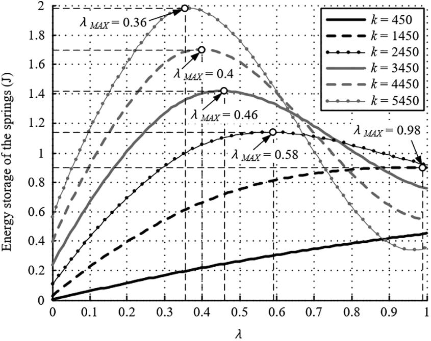
The energy storage performance with different k. The unit of k is N/m. λMAX is the value of λ at the maximum energy storage.
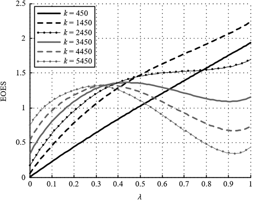
The characteristic of EOES with different k. The unit of k is N/m. EOES: efficiency of energy storage.
Error of the experiment caused by locking mechanism
The locking mechanism consisted of pawl and spinous slide axis. Although this mechanism is convenient to lock the position of the fixed end, and the locking force is hard enough, the friction between pawl and axis affects the performance of the device seriously. The friction is difficult to measure, since it is unsmooth and vibrant during the motion process. Therefore, it is necessary to modify the locking mechanism to decrease the effect of locking process on the energy storage performance, and this is also the future direction of our work.
Conclusion and future work
In this article, we present the mechanism and structure of a biomimetic TE-VSEA device and analyze the energy storage performance, especially the EOES of this device. The simulation explains how much energy could be stored in this device and the variation trend of the storage value. The experiment basically verifies the variation trend of storage and EOES. At last, the performance of this device, the reason of the energy loss and the experiment error have been discussed, and a special EA device has been shown at λ = 1.
The simulation result indicates that, during the motion process of the cylinder, this device can store 1.415 J energy at λ = 0.46, and maximum EOES is 1.3608 at λ = 0.45, when the weight of the TE-VSEA device is 3.54 kg, the apparent stiffness is about 3450 N/m and the initial length of each spring is their nature length. The maximum energy storage and EOES are greater than the values of the SEA and the special EA, which are the limit state of this device at λ = 0 and λ = 1.
Based on the findings of this study, our future work will be on the coupling characteristics of the two springs, the modified locking mechanism, the effect of the apparent stiffness variation on the storage performance in detail, and the special EA device mentioned in the subsection “Performance and a special situation.”
Footnotes
Declaration of conflicting interests
The author(s) declared no potential conflicts of interest with respect to the research, authorship, and/or publication of this article.
Funding
The author(s) disclosed receipt of the following financial support for the research, authorship, and/or publication of this article: This work was financially supported by the National Natural Science Foundation of China (Fund number 50975230).