
Abstract
The compressed air energy storage system has a better energy density, while the widely used hydraulic one is superior in power performance. Therefore, they are suitable for different hybrid vehicles, which require a comparative study on the performances and vehicle applicability of the broad pressure energy storage system layouts. In this paper, an integrated mathematical model of four basic pressure layouts is presented for characteristic analysis and applicability discussion. Results show that the open volume layout achieves the best power performance with the flow specific power of 13.92 MJ/m3, thus it is suitable for heavy hybrid trucks and mobile machinery. The open mass layout achieves the best energy performance with the energy density of 124.35 MJ/m3, which can be used in light new energy passenger vehicles. And the performance of the closed volume layout is close to the open volume layout with the flow specific power of 9.78 MJ/m3, so it could be applied to middle and light hybrid trucks. This research provides a basis for the hybrid method of pressure energy storage system layouts for vehicles, and could be applied in the design and research of non-electric hybrid vehicles in the near future.
Keywords
Introduction
The aggravation of environmental crisis and increasing oil shortage brings an urgent need for the development of energy-saving technology. 1 And the energy storage technology for hybrid vehicles is one of the key elements in that. 2 So far, multiple energy storage approaches have been studied. 3 And the most popular one is the electric hybrid vehicle. 4 It has been commercially produced and widely used for years. 5 Although it has the advantages of relatively high energy density, 6 limitations of Li-ion batteries lead to low power density, short lifespan, and high initial cost and replacement cost of the energy storage system (ESS) 7 hinder its further applications on hybrid powertrains. 8 Thus, there is a need to explore other feasible energy storage approaches for hybrid vehicles in more extensive scenarios. 9
Literature review
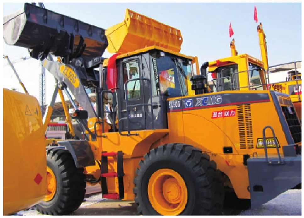
In contrast to the battery ESS, the hydraulic ESS has features of high power density, 10 low costs, and long lifespan. 11 So it has been widely applied to heavy-duty trucks and mobile machinery such as excavators and loaders (shown in Figure 1) for a long time. 12 In 2010, Parker Hannifin Corp. developed a heavy hydraulic hybrid truck equipped with an intelligent system. 13 The year later, Xuzhou Construction Machinery Group (XCMG) launched the ZL50G hydraulic hybrid loader, as shown in Figure 2. 14 And there are many studies related to this hybrid approach nowadays. 15 Hui and Jing 16 carry out experimental research on a parallel hydraulic hybrid loader. The results data show that the braking energy recovery rate under a typical operation cycle is 60.03%, which is high in energy recovery performance. Some relevant experiments conducted by the U.S. Environmental Protection Agency (EPA) and other research institutions show that the hydraulic hybrid technology is the most effective energy-saving path for medium and heavy vehicles, which can improve vehicle fuel economy by 20%–40%. 17 And its estimated energy saving potential can even reach 80%. Despite these advantages, the hydraulic ESS has a low energy density, 18 which makes it incompetent for applications that require large energy recovery and storage. 19

A loader of Caterpillar Inc.
The ZL50G hydraulic hybrid loader of XCMG.
Different from the hydraulic hybrid vehicle, the compressed air vehicle is a new type of green vehicle with the advantages of high energy density and low cost. 20 The pressure energy of high-pressure air in the air storage unit is converted into mechanical energy to drive the vehicle by a pneumatic compressor/motor. 21 This technology was originally used in compressed air energy storage (CAES) in power plants. 22 By compressing and releasing compressed air stored in underground caves via pneumatic compressors and motors to store and generate electric energy, the power grid load could match the intermittent renewable energy sources with customer demand. 23 And now, there is some research that applies this technology to vehicles. 24 Motor Development International (MDI) is the first company in the world to realize the industrialization of pneumatic vehicles. 25 At the 2009 Geneva International Motor Show, the company displayed a pneumatic vehicle named “airpod.” With a volume of 175 L of air tanks and 220 kg vehicle weight, the airpod’s driving range can reach 200 km. After that, the company continued to develop the “airpod2.0,” 26 as shown in Figure 3. Its air storage unit expands to 250 L and the driving range now has reached 360 km. Nevertheless, the relatively low power density and energy efficiency of the existing compressed air ESSs, 27 the frosting problem, as well as the lack of compressed air filling equipment and other supporting facilities, 28 all together impede the further development of compressed air vehicles. 29
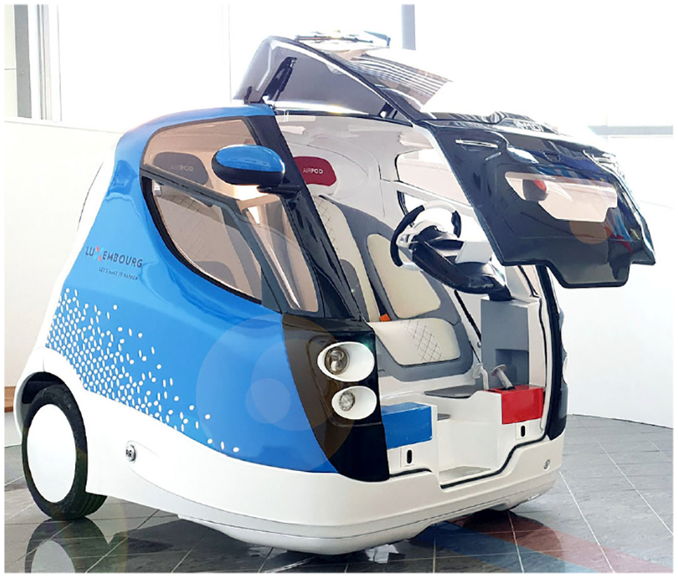
The airpod2.0 of MDI.
Similar to the compressed air ESS with a pneumatic compressor/motor, the one with a pneumatic hybrid engine is also a compressed air ESS approach. The pneumatic hybrid engine is put forward by Schechter, and the idea behind this engine is to run the internal combustion engine in two modes (i.e. regular engine mode and pneumatic compressor/motor mode) by changing the valve timing. 30 Subsequently, Schechter proposes to install an inflation valve at the end of the cylinder of the engine to connect with the air tank, so that air can be compressed from the air cylinder into the tank, or the other way around. During a 45 s cycle scenario, the experimental results show that the fuel consumption rate is reduced by 50%. To further improve the energy density of the compressed air, Fazeli et al. 31 suggests mixing the inhaled ambient air with the remaining high-pressure air from the last compression cycle, as shown in Figure 4. In this way, the air inflation process of engine is improved, so as the system’s energy density.

The pneumatic hybrid engine with the intermediate tank.
Compared with the widely used open ESS layouts, the closed layouts could significantly increase the total power density and efficiency of the system. From this point of view, two schemes were carried out. Regular hydraulic ESSs pump oil in and out between the main hydraulic accumulator and the oil tank, while a close layout of hydraulic ESS replaces the latter with an auxiliary low-pressure accumulator. It brings the features of dustproof, anti-oxidation, and backpressure for the ESS, which is suitable for light hybrid vehicles. 32 The world’s major logistics companies choose hydraulic hybrid vehicles to reduce the overall fuel consumption of the fleet, such as FedEx Express, United Parcel Service Inc. (UPS), Waste Management, etc. And now, these companies equipped their fleet with a considerable proportion of hydraulic hybrid vehicles, 33 as shown in Figure 5. A hydraulic hybrid delivery truck developed and equipped by UPS performs a better fuel economy by 60%–70% compared with the regular counterparts in EPA laboratory tests. 34 Lloyd studies the regenerative braking system of the hydraulic hybrid delivery truck. The results show that the ESS can not only increase the service life of the vehicle, but also halve the fuel consumption for the same mileage. 35 Groupe PSA (the former Peugeot Société Anonyme), presented a hydraulic hybrid passenger vehicle based on Peugeot 208 chassis in the 2016 Geneva International Auto Show, 36 as shown in Figure 6. It presents a fuel consumption per hundred kilometers of 2 L. Moreover, the hydraulic hybrid technology has been applied to buses in Japan, with the driving cycle tests in three cities including Tokyo. 37 The results show that the fuel economy is improved by 20%.

A hydraulic hybrid refuse truck of Miami-Dade County.

The hydraulic hybrid power system based on Peugeot 208 chassis.
Similar to the close layout of hydraulic ESS, the close layout of compressed air ESS adds an auxiliary low-pressure air tank to the system. It can significantly improve the power density of the ESS. Andersson 38 developed an ESS with two air containers for commuter buses. By this means, the energy recovery rate of the compressed air ESS rises up to 50% during braking.
As a comprehensive comparative study of the above pressure ESSs and electric ESSs, Jin et al. 39 explore different research routes of ESSs for hybrid mining trucks. It includes battery ESS, hydraulic ESS, supercapacitor ESS, and compressed air ESS. And the paper concludes that the hybrid mining trucks with hydraulic ESS and compressed air ESS have better economic benefits than electric ESSs. Moreover, the results show that hybrid mining trucks with hydraulic ESS could achieve better energy recovery performance than compressed air ESS.
Challenges and contributions of the research
All of the above pressure ESS layouts have the advantages of low cost and long lifespan compared with battery ESS. 40 Among them, the compressed air ESS has a better energy density, 31 while the hydraulic ESS is superior in power performance. 41 Thus they are suitable for different hybrid vehicles. So far, there are few works of literature present a comprehensive comparative study on the performances and applicability of the broad pressure ESS layouts.
In this paper, an integrated mathematical model of four basic pressure layouts is presented for characteristic analysis and applicability discussion. This research provides a basis for the hybrid method of pressure energy storage system layouts for vehicles, and could be applied in the design and research of non-electric hybrid vehicles in the near future.
Organization of the paper
The next chapters are organized as follows: Chapter 2 carries out the definition and classification of broad compressed air and hydraulic ESS layouts. Chapter 3 presents the performance analytic model of four basic layouts. Chapter 4 details the simulation results, analyses their energy and power characteristics, and discusses their applicability on hybrid vehicles. Chapter 5 draws conclusions. Chapter 6 shows the prospect.
Definition and classification of broad compressed air and hydraulic ESS layouts
This chapter presents the definition and classification of the broad compressed air and hydraulic ESSs. Also, four basic layouts are obtained, and their features and performances are discussed.
Volume layout and mass layout
This section defines and classifies the volume layout and mass layout, and their features and performances are discussed.
According to the thermodynamic laws,
42
for uncharged compressed air ESS, the specific pressure exergy
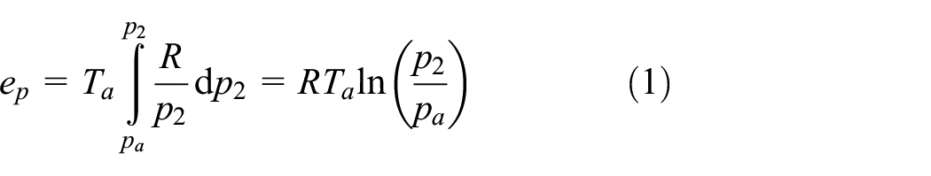
where
Based on the ideal gas state equation with the pressure

where,
A typical open volume layout is the hydraulic ESS without auxiliary low-pressure accumulator units. They are widely applied in heavy-duty hybrid trucks and mobile machinery. 44 These vehicles frequently start and stop in their operation process. 45 Due to the heavy weight, a large amount of energy will be released during braking. 46 And most of these vehicles are equipped with working devices that have periodic workloads. 47 Thus, Using hydraulic ESS to store and reuse these recoverable high-power energy has become an effective approach for saving energy and reducing consumption. 48 Figure 7 is the structure sketch of a hydraulic hybrid loader’s powertrain. 16 And Figure 8 is the simplified layout of the corresponding pressure energy storage. The layout consists of a main hydraulic accumulator, a hydraulic pump/motor, and an oil tank. During the regenerative braking and energy recovery process, mechanical energy is converted into pressure energy stored in the hydraulic accumulator by the hydraulic pump, and vice versa in the subsequent acceleration or operation process. 49

A hydraulic hybrid loader’s powertrain.
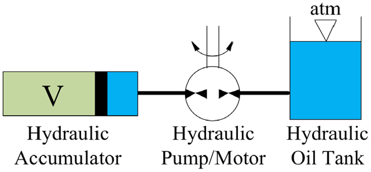
The open volume layout.
A typical open mass layout is comprised of a main air tank and a pneumatic hybrid engine (or a pneumatic compressor/motor). So far, this layout is mainly used in light passenger vehicles. Because of its high energy density and low cost, it is a feasible environmental and energy-saving ESS approach for new energy urban vehicles. 50 Figure 9 is the structure sketch of a compressed air ESS with a pneumatic hybrid engine. 30 And Figure 10 is the simplified layout of the corresponding pressure energy storage. During the driving process, the pressure energy of compressed air in the air tanks is converted into mechanical energy to drive the vehicle by the pneumatic motor (or a pneumatic hybrid engine), and vice versa in the regenerative braking process. 51

A compressed air ESS with a pneumatic hybrid engine.

The open mass layout.
Open layout and closed layout
This section defines and classifies the open layout and the closed layout, and discusses their features and performances.
For broad compressed air and hydraulic ESSs, systems exchanging volume or mass with the ambient air are referred to as open layouts, such as the above open volume layout and open mass layout. Whereas, systems that have one main subsystem exchanging volume or mass with another auxiliary subsystem are referred to as closed layouts.
Different from the open volume layout which is mostly used in heavy-duty trucks and mobile machinery, the closed volume layout is suitable for middle and light hybrid vehicles. 52 This is mainly because the former usually have large hydraulic systems themselves, which have large oil tanks and could provide backpressure for the ESS. And since the oil in the open hydraulic systems has already been changed regularly, the ESSs do not need the features of dustproof and anti-oxidation from the close volume layout, which is required for light hybrid vehicles. Figure 11 is the structure sketch of a hydraulic hybrid powertrain of the PSA hybrid passenger vehicle. 36 And Figure 12 is the simplified layout of the corresponding pressure energy storage. The layout consists of a main high-pressure hydraulic accumulator, a hydraulic pump/motor, and an auxiliary low-pressure accumulator. During the regenerative braking process, mechanical energy is converted into pressure energy stored in the high-pressure hydraulic accumulator by the hydraulic pump, while the nitrogen in the low-pressure accumulator expands to provide backpressure, and vice versa in the subsequent acceleration process. 53

A hydraulic hybrid powertrain of the PSA hybrid passenger vehicle.

The closed volume layout.
For the closed mass layout, the related research is few. However, it is a promising ESS layout that has the advantages of high power density and low cost. Moreover, it is a pneumatic system without the requirement of additional hydraulic components, so it is suitable for the powertrain with an integrated pneumatic hybrid engine. The major applications are hybrid commuter buses. Figure 13 is the structure sketch of a pneumatic hybrid powertrain of a hybrid commuter bus. 38 And Figure 14 is the simplified layout of the corresponding pressure energy storage. The layout consists of a main high-pressure air tank, a pneumatic hybrid engine (or a pneumatic compressor/motor), and an auxiliary low-pressure air tank. During the regenerative braking process, mechanical energy is converted into pressure energy by the pneumatic hybrid engine (or the pneumatic compressor), while the low-pressure air in one air tank is compressed into the other air tank with high-pressure air, and vice versa in the acceleration process.

A pneumatic hybrid powertrain of a hybrid commuter bus.

The closed mass layout.
Four basic layouts
Based on the above definition and classification of the broad compressed air and hydraulic ESS layouts, four basic layouts are shown in Figures 8, 10, 12 and 14, respectively. Specifically, the open volume layout (regular hydraulic ESS) with a single hydraulic accumulator (shown in Figure 8), the closed volume layout with double hydraulic accumulators (shown in Figure 12), the open mass layout (regular compressed air ESS) with a single nitrogen tank (shown in Figure 10), and the closed mass layout with double nitrogen tanks (shown in Figure 14). The corresponding power and energy characteristics of these layouts will be discussed and analyzed in the next chapter.
The integrated performance analytic model of four basic layouts
Based on the two indicators: energy density
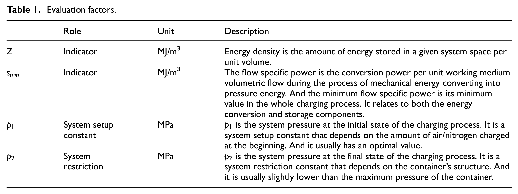
Evaluation factors
This section studies the evaluation factors of the energy and power performances of the four basic pressure layouts.
Energy density and power density are two important indicators to evaluate the performance of ESSs. The energy density refers to the energy per unit volume during the working process. Whereas, the power performances are mainly dependent on features of the energy conversion components due to their physical limitations such as the maximum displacement and speed. The flow specific power in ESSs will be affected by operating conditions (e.g. the maximum pressure) and layouts (e.g. open or closed) of energy storage components. Both the minimum flow specific power
Meanwhile, system pressures, especially the initial and final pressures of the main and auxiliary energy storage components are major considerations. Thus, system pressures and their relations are discussed in each section of the four basic layouts. These main evaluation factors are shown in Table 1.
Evaluation factors.
The open volume layout
This section studies the energy and power performances of the open volume layout.
Systems exchanging volume with the ambient air are referred to as open volume layout, which is usually a hydraulic ESS with a single hydraulic accumulator.
When the system without pre-stored energy is fully charged, the stored energy

where
Whereas the pre-stored energy

where
According to (1), Boyle’s law
54
and the equation of ideal gas,
43
the stored energy
For open volume layouts, the system volume

By the definition of the power of the hydraulic pump, the input power

where
Thus the flow specific power

Therefore, when the system pressure
The open mass layout
This section studies the energy and power performances of the closed mass layout.
Systems exchanging air with the ambient air are referred to as the open mass layout, which is usually a compressed air ESS with a single air tank.
When the system without pre-stored energy is fully charged, the stored energy is given by the following expression 55 :
where
Whereas the pre-stored energy of the system at the initial state can be calculated by:

where

For the open mass layout, the system volume is

By the definition of the pneumatic compressor power, the input power of open mass layout can be expressed as:

Thus the flow specific power can be defined as:

Therefore, when the
The closed volume layout
This section studies the energy and power performances of the closed volume layout.
Systems including one subsystem exchanging volume with another subsystem are referred to as the closed volume layout, which is usually a special hydraulic ESS with double hydraulic accumulators.
In the charging process, the volume
The above closed volume layout is equivalent to the system coupling of two virtual systems with open volume layout, as shown in Figure 15: The virtual system D (shown in Figure 15(a)) composed of the main accumulator B and a virtual ambient air C with constant pressure

The virtual system for closed volume layout: (a) virtual system D, (b) virtual system E, and (c) closed volume layout.
Accordingly, the stored energy
where
While the released energy

where
Thus, the stored energy of the system at the final state can be defined as:

The volume exchange of the system actually occurs between B and A, which is given by:

where
For closed volume layout, the system volume
By the definition of the power of the hydraulic pump, the input power of closed volume layout can be expressed as:

where
Thus, the flow specific power can be defined as:

For general closed volume layouts,
At the initial state, the
Above all, both the energy and power performances of the closed volume layout are inferior to the open volume layout. While there are two unique advantages of the former layout, one is that the auxiliary accumulator can provide backpressure for the hydraulic system, and the other is the closed layout realizes the dustproof and anti-oxidation features. Therefore, the power and energy performance of a practical closed volume layout should be as close to the corresponding open volume layout as possible.
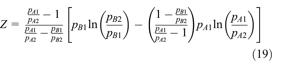
Based on (19), for a given
As a closed volume layout with pre-stored energy has unbalanced initial pressures (

The energy and power performances of the closed volume layout.
The closed mass layout
This section studies the energy and power performances of the closed mass layout.
Systems including one subsystem exchanges air with another subsystem are referred to as the closed mass layout, which is usually a special compressed air ESS with double air tanks.
In the charging process, the air mass
The above closed mass layout is equivalent to the system coupling of two virtual systems with open mass layout, as shown in Figure 17: The virtual system D (shown in Figure 17(a)) composed of the main air tank B and a virtual ambient air C with constant pressure

The virtual system for closed mass layout: (a) virtual system D, (b) virtual system E, and (c) closed mass layout..
Accordingly, the stored energy
where
While the released energy

where
According to the equation of ideal gas, 43 the mass exchange of the system actually occurs between B and A, which is given by:
By Boyle’s law, 54 the stored energy of the system with pre-stored energy at the final state can be defined as:

For the closed mass layout, the system volume

By the definition of the power of pneumatic compressors, the input power of closed mass layout can be expressed as:

Therefore, the flow specific power can be defined as:

For practical closed mass layouts,
Comparing (28) and (14), the
Above all, although the
Based on (26), for a given

The energy and power performances of the closed mass layout.
In Figure 18, the
The actual performance of a certain closed volume layout should be between the optimal energy and the optimal power performances, where there is a gap that makes it difficult to balance the two characteristics, as shown in Figure 18. Therefore the performance of the closed volume layouts is represented by the two layouts: one with the optimal energy configurations and another with the optimal power configurations, the performance of an actual closed volume layout should between the two.
Results and discussion
Based on the above integrated performance analytic model of four basic pressure layouts, this chapter simulates and analyzes the energy and power performances of the four layouts. The simulation results are shown in Figures 19 to 22. And their applicability for hybrid vehicles is discussed.
The energy performance of the four basic pressure layouts.
The energy performance of the four basic pressure layouts (enlarged figure).
The power performance of the four basic pressure layouts.
The power performance of the four basic pressure layouts (enlarged figure).
Energy performance analysis
This section studies the energy performances of the four basic pressure layouts based on the simulation results.
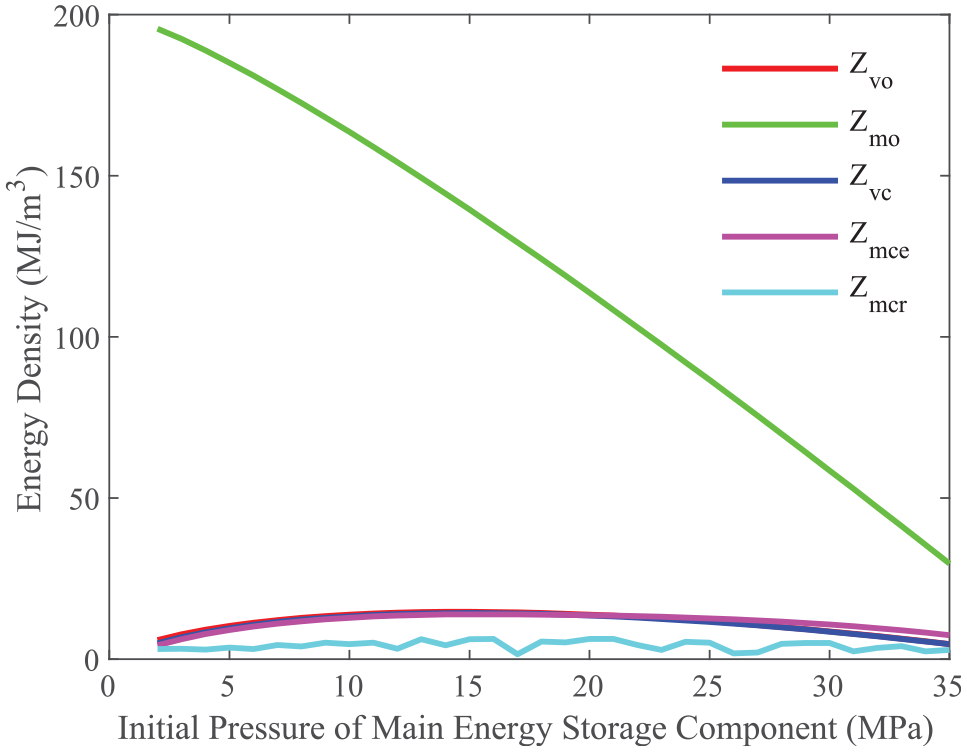
Figure 19 shows the energy performance with initial pressure
The curves of the energy density of the open volume layout
To sum up, the energy performance of the four basic pressure layouts could be summarized as below: The open mass layout presents the best energy performance. And it has the best energy performance where the system does not have pre-stored energy at the initial state, which is more than ten times than the rest. The open volume layout possesses the second-best energy density but only a tenth of the open mass layout, which reaches its maximum value when
Power performance analysis
This section studies the power performances of the four basic pressure layouts based on the simulation results.
Figure 21 shows the power performance with initial pressure
Different from the above, the minimum flow specific power of the open mass layout
To sum up, the power performance of the four basic pressure layouts could be summarized as below: The open volume layout presents the best power performance. And it performs better when the initial pressure is higher. The closed volume layout and the close mass layout with optimal power configurations exhibit about 70% and 40% of the power performance of the open volume layout. And the open mass layout and the close mass layout with optimal energy configurations show poor power performance compared with above. Since the power performance of an actual closed volume layout is between the two configurations, it has a minimum flow specific power higher than the open mass layout.
Applicability for hybrid vehicles
This section discusses the applicability of the four basic pressure layouts for hybrid vehicles based on the above analysis.
Based on the above energy and power performances analysis of four basic pressure layouts, their quantitative values in practical applications could be chosen according to the following considerations. The open volume layout, closed volume layout, and closed mass layout with optimal power configurations has relatively high flow specific power, so their actual scheme should choose the setting points with the largest energy density, as shown in Figures 19 and 20. Therefore, the actual energy density and flow specific power of these three layouts are 14.79, 13.92, 14.32, 9.78, 6.73, 5.36 MJ/m3, respectively, as shown in Table 2. And for the close mass layout with optimal energy configurations, it should choose the setting point with both high energy density and flow specific power, which is 13.81 and 1.15 MJ/m3 respectively when
Parameters of vehicles and ESSs.
Considering the working conditions of vehicles of different types, the driving cycle of heavy hybrid vehicles, middle hybrid vehicles, and light new energy vehicles are introduced. A heavy hybrid vehicle and a middle hybrid vehicle, whose specifications are shown in Table 2, are selected to evaluate the applicability of different layouts. They are mainly used in urban and suburban transportations, thus the New Europe Driving Cycle (NEDC) is adopted, as shown in Figure 23. And a light new energy vehicle, with a driving range of 90 km, is selected. Considering the demand for highway driving, the Highway Fuel Economy Test (HWFET) driving cycle is adopted, as shown in Figure 24. To minimize the fuel consumption of the vehicles, the energy management strategy is obtained by the Dynamic Programming (DP) algorithm. Based on the demand power of ESSs, the corresponding required energy density and flow specific power for these vehicles are obtained, as shown in Figures 25 and 26.
New europe driving cycle.

Highway Fuel economy test.
The layouts’ energy applicability for different vehicles.

The layouts’ power applicability for different vehicles.
Although all of the four basic layouts, as pressure layouts, have the advantages of low cost and long lifespan, their distinct energy and power performances as well as other properties make them suitable for different vehicle applications. Thus, based on the above performance analysis, several conclusions for application can be generalized.
It can be seen from Figures 25 and 26, the open volume layout presents the best power performance and moderate energy performance. And as a mature technology, it has a high energy conversion efficiency. So it is suitable for heavy hybrid vehicles which frequently start and stop in their operation process for high power breaking or workload recovery. Thus for a vehicle that already has an original hydraulic system of the working device, such as heavy trucks and mobile machinery, it is a good hybrid ESS option.
While the open mass layout shows the best energy performance but a poor power performance. Since it is the only pressure layout that possesses a large energy capacity, it suits new energy vehicles. Thus, in situations that demand large energy capacity which does not need good power performance, such as light new energy passenger vehicles, the open mass layout could be the right choice. And considering its potential option for the hybrid internal combustion engine (ICE) with compressed air, 56 it could also be applied in light passenger vehicles with an integrated pneumatic hybrid ICE.
And the closed volume layout exhibits the second-best power performance and moderate energy performance. Just like the open volume layout, it is also a mature technology and has a high energy conversion efficiency. As for closed volume layouts with unique advantages such as dustproof, anti-oxidation, and backpressure, it is a powerful competitor to the open volume layout, especially for middle and light hybrid trucks which do not have a large hydraulic system except the ESS.
The closed mass layout presents a moderate power performance and a poor energy performance. So it is only suit for middle hybrid passenger vehicles such as commuter buses, which frequently start and stop in their operation process for high power breaking recovery. And just like the open mass layout, it could also be used in middle vehicles with an integrated pneumatic hybrid ICE. Although its flow specific power is lower than the required one of middle vehicles in Figure 26, for those who have pneumatic hybrid ICE with large displacement, the overall ESS power shall meet the demand.
Summary
The above analysis and discussion can be summarized as below: The open volume layout presents the best power performance and moderate energy performance, which is suitable for heavy hybrid trucks and mobile machinery; While the open mass layout shows the best energy performance but a poor power performance, and it could be applied in light new energy passenger vehicles. And the closed volume layout exhibits the second-best power performance and moderate energy performance that can be used in middle and light hybrid trucks. As for the closed mass layout with moderate power performance and poor energy performance, it is only suited for middle hybrid passenger vehicles. The above summary is shown in Table 3.
Energy and power performances, properties, and applicability of four basic pressure layouts.

Conclusions
The definition and classification of broad compressed air and hydraulic ESS layouts are presented in this research with the aim to give an evaluation of various pressure ESSs. Four basic layouts of compressed air and hydraulic ESSs are proposed. An integrated analytical model is carried out for these layouts, the corresponding system performance is analyzed, and the feasibility of their applications in different vehicles is evaluated. Here shows the main conclusions:
Results show that the open volume layout achieves the best power performance with the flow specific power of 13.92 MJ/m3, the open mass layout achieves the best energy performance with the energy density of 124.35 MJ/m3, and the performance of the closed volume layout is close to the open volume layout with the flow specific power of 9.78 MJ/m3, while the performance of the closed mass layout is inferior to others.
The open volume layout is suitable for heavy hybrid trucks and mobile machinery. While the open mass layout can be used in light new energy passenger vehicles. And the closed volume layout shall be applied to middle and light hybrid trucks. As for middle hybrid passenger vehicles, the closed mass layout could be adopted.
Based on the above conclusions, a basis for the hybrid method of pressure energy storage system layouts for vehicles is provided. Thus, the present study could be applied in the design and research of non-electric hybrid vehicles in the near future.
Prospect
The system performances of the four basic pressure layouts of compressed air and hydraulic ESSs are analyzed, and their applications in different vehicles are discussed in this paper. And for a more accurate evaluation of these ESSs’ performances on vehicles, the next step is to carry out an integrated simulation of the ESS with the vehicle dynamics system.
Footnotes
Appendix
Acknowledgements
The authors, therefore, acknowledge with thanks to Ministry of Science and Technology of the People’s Republic of China and Shunde Graduate School of University of Science and Technology Beijing, for the technical and financial support.
Handling Editor: Chenhui Liang
Author contributions
Conceptualization, Tong Yi and Yanbo Liu; methodology, Jichao Hong and Yanbo Liu; software, Tong Yi and Jichao Hong; validation, Yanbo Liu and Tong Yi; formal analysis, Jichao Hong; investigation, Jichao Hong and Tong Yi; resources, Tong Yi and Yanbo Liu; data Curation, Yanbo Liu and Jichao Hong; writing – original draft preparation, Tong Yi; writing – review and editing, Jichao Hong, Tong Yi, and Chun Jin; visualization, Jichao Hong and Yanbo Liu; supervision, Chun Jin; project administration, Tong Yi and Chun Jin; funding acquisition, Chun Jin. All authors have read and agreed to the published version of the manuscript.
Declaration of conflicting interests
The author(s) declared no potential conflicts of interest with respect to the research, authorship, and/or publication of this article.
Funding
The author(s) disclosed receipt of the following financial support for the research, authorship, and/or publication of this article: This research was funded by Ministry of Science and Technology of the People’s Republic of China, grant number 2016YFC0802905, and Shunde Graduate School of University of Science and Technology Beijing, grant number BK19BE003.