
Abstract
Faced with the problem of frequent slippage of the wheel-arm inspection robot in overhead high-voltage transmission lines, a magnetic linear drive method, based on high-voltage direct current (HVDC) magnetic field, is proposed: The ampere force of an enhanced HVDC magnetic field, generated by an innovatively arranged current-carrying coil, is used as the driving force for the traction robot, replacing the traditional wheel-arm driving method, thereby eliminating the slip. A physical model for the magnetic driving force is established, according to the characteristics of the magnetic field around the HVDC transmission line and the driving force requirements of the robot. The relationship between the magnetic driving force, the physical model size, and the number of coil windings is analyzed. The magnetic drive model is simulated using the COMSOL software version is 5.0. The simulation results of the magnetic drive force model are compared to theoretical calculations, proving the proposed method as correct. The magnetic drive device is constructed according to the proposed magnetic drive model and experiments are carried out. The results show that the magnetic drive device can provide enough traction to drive the robot motion, proving that the proposed magnetic linear drive method is technically feasible.
Introduction
In 1988, Toshiba Corporation of Japan and Tokyo Electric Power Co., Ltd, Japan, pioneered the development of a high-voltage line mobile inspection robot. 1 Since then, the United States, Canada, Brazil, and other countries were also presented the different high-voltage line inspection robots. Some well-known works include the “LineScout” inspection robot 2 –4 of the Quebec Hydropower Research Institute of Canada, Paulo Debenest of Japan HiBot Company, and “Expliner” inspection robot 5 developed by HiBot Company, Paulo Debenest, and others, but the transmission line inspection robots research was started late in China. In the 1990s, research and development work on transmission line inspection robot technology was successfully carried out. 6 –8 Compared to manual and helicopter inspection, the robot approach has the advantages of low cost, strong environmental adaptability, safety and reliability, and long battery life. For example, the inspection robots that travel along the high-voltage ground line developed in the study 6 was used in the power system overhaul department of China. Another successful application is inspection robot traveling along high-voltage wires 7 used in the power supply department of China achieving good results.
Although many high-voltage inspection robots were proposed, 9 –12 they still faced many technical problems. Most of the high-voltage inspection robots with wheel-arm structure have the problem of slip of walking wheels in the case of abnormal surface conditions (such as ice coating) or when the robot is running on a steep slope, the static friction is not enough to overcome gravity and slip. Slipping seriously affects the inspection efficiency of the robot, which increases energy consumption and damages the transmission system. When skidding is severe, the robot is difficult to control. At present, most researchers reduce the occurrence of skids by optimizing the structure of the robot. Research of authors from Isfahan University of Technology 10 proposed a structural optimization method. Research of authors from Wuhan University 12 proposed a balance control method to avoid skids by balancing the load on the front and rear wheels. To solve this problem fundamentally, the slipping problem should be improved by changing the driving method of the inspection robot.
The realization of maglev technology 13,14 and the rapid development of ferrite soft magnetic materials 15 –17 provide a new research idea to solve the problem of the slip of the inspection robot. In this article, the energized coil is appropriately arranged around the high-voltage line that offers the annular magnetic field, which is enhanced by the soft magnetic material, and then, the ampere force is received by the energized coil, therefore, the ampere force is used to drive the inspection robot during the inspection processing. Thus, the problem of slippage and wear during the operation of the robot is fundamentally eliminated, which resulted from the wheel-arm drive structure.
Magnetic linear drive principle
Analysis of magnetic field characteristics of overhead high-voltage direct current transmission lines
Overhead high-voltage direct current (HVDC) transmission lines are generally classified into two types: unipolar and bipolar lines (Figure 1). The unipolar lines use a single high voltage to transmit electricity, forming a loop with the earth or seawater; the bipolar lines use two high-voltage lines of different polarity to transmit electricity.

The types of overhead HVDC transmission line: (a) unipolar line and (b) bipolar line. HVDC: high-voltage direct current.
As shown in Figure 1(a), the magnetic field generated by a single high-voltage line of a unipolar line is not disturbed by the outer environment, and the magnetic lines around the wire are a series of concentric circles perpendicular to the wire. Considering the influence of magnetic fields from the multiple adjacent high-voltage lines, the magnetic field interference may be generated in the bipolar circuit, which is shown in Figure 1(b). As shown in Figure 2, the characteristics of the magnetic field are analyzed in the bipolar line. The high-voltage lines a and b are, respectively, two wires of the bipolar line with currents almost equal in magnitude and of opposite directions. Assuming that the inspection robot is walking on the high-voltage line a, Q is the point near the high-voltage line a, and the magnetic induction strength of the high-voltage lines a and b at the Q point to be as Ba and Bb , thus, the vector sum is the Bab . The distance between the two high-voltage lines is Lab , and the distance from the Q point to the high-voltage line b is LbQ , the angle between the line connecting the Q point and the high-voltage line a and the horizontal direction is θ (0° ≤ θ ≤ 360°).
Bipole line with magnetic field analysis. 1 indicates high-voltage line b, 2 indicates magnetic induction line, and 3 represents high-voltage line a.
According to the cosine theorem, it can be obtained

When the distance between the two high-voltage lines a, b is the minimum (i.e. the Q point falls on the a, b line), the magnetic field of the high-voltage line b at the Q point is the strongest, and the magnetic field interference of the high-voltage line a at the Q point is the highest. That is, when

According to Biot–Savar law, it can be concluded that the magnetic induction line of a single long straight wire is along a concentric circle perpendicular to the plane of the wire, and the magnetic induction B generated by the straight wire can be derived as

where vacuum permeability u 0 = 4π × 10−7 H/m, I is the DC conductor current, and r is the vertical distance of a point in space from the centerline of the wire.
According to equations (1) to (3), the magnetic field strength ratios of the high-voltage lines a and b at the Q point are

where I 0 represents the magnitude of the high-voltage line current.
At present, the traditional interelectrode distance of China’s UHV DC transmission line is 22 m 18 with Lab = 22 m. The magnetically driven inspection robot avoids the problems of the wheel-arm inspection robot and may be assumed that it operates within a radius of 0.2 m. Substituting the above values into equation (4)
It can be seen that Bb is much smaller than Ba , thus, the magnetic field strength of the high-voltage line b at the Q point can be negligible compared to the magnetic field strength of the high-voltage line a at the respective point. This means that the magnetic line of inductance generated by the high-voltage line a is approximated as a concentric circle perpendicular to the high-voltage line, therefore, the magnetic field generated by the bipolar line can be equivalent to that generated by the unipolar line.
Magnetic drive model design
At present, the wheel-arm structure adopted by the high-voltage inspection robots exposes shortcomings, such as the structure is not compact, large size, large weight of the body, and poor wind load resistance. In the magnetic linear driving mode, these disadvantages can be effectively avoided because of the changes in the mechanical structure. The inspection robot adopts the overall structure, as shown in Figure 3. The main part of the robot is shown in Figure 4.
Overall structure of the magnetic inspection robot. 1: Counterweight workbench; 2: main body of the robot; 3: high-voltage line a.

Main body of the robot. 1: Screw mechanism; 2: linkage mechanism; 3: partition; 4: magnetic drive device limiting slot; 5: walking wheel mechanism; 6: wire protector.
According to the characteristics of the magnetic field, the direction around which the direct current generated is determined, reasonable arranging the coil around the high-voltage line, so that the coil is subjected to ampere force in the magnetic field, which generated by the high-voltage line. This generated force is used as the driving force for the direct traction of the robot. The magnetic drive physical model is shown in Figure 5 (longitudinal section of the cylindrical robot, where only the magnetic drive part is shown). One long side (L 1) of the rectangular-shaped winding of the current-carrying coil is placed in the soft magnetic material and the other long side is placed in the weak magnetically permeable material. This arrangement strengthens the magnetic field increasing the amperage. The magnetic drive solid model is shown in Figure 6. The magnetic drive system is divided into two parts: the left and the right body (a structure serving well the opening and closing action of the body) and the current-carrying coils that wind around the left and the right body, respectively. To facilitate the construction of the model, the coil is considered equivalent to a plurality of independent rectangular coils. To prevent magnetic leakage, 3D printing or sintering process is used to seamlessly embed the coil in the soft magnetic material. Furthermore, to simplify the manufacturing process of the magnetic drive system, the long side ends of the coils may be sequentially connected by welding or the like, as the short sides of the coils are placed in the weak magnetic conductive material.

Physical model of magnetic drive.
Solid model of magnetic drive.
The energized coil is subjecting to ampere force in the magnetic field. According to Ampere’s law, the amperage force F = BILsinθ. Based on the above, the current-carrying coil and the annular magnetic induction line around the high-voltage power transmission line are perpendicular to each other, that is, θ = 90°, so F = BIL. The strength of the magnetic field on each side of the long-lengthened part of the coil is not equal, so the ampere force of the long side of the rectangular coil placed in the weakly magnetically permeable material is
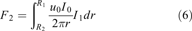
where R 1 and R 2 are the vertical distances from the centerline of the HVDC transmission line to the coil sides L 1 and L 2, I 0 is the high-voltage line current, and I 1 is the current of the coil.
The other long side L 1 of the current-carrying coil is placed in the soft magnetic material, and so, the enhanced magnetic induction B 1 is

where u r is the relative permeability.
The ampere force F 1 of the long side of the current-carrying coil in the soft magnetic material is

Since the magnetic drive system is composed of left and right symmetrical bodies, the wound coils are arranged symmetrically with the high-voltage line being the centerline. Also, the ampere forces of the short side of the rectangular coil of the left and right body cancel each other. That is, the resultant force F 0 of a single coil is

Without considering magnetic field coupling and other conditions, the total thrust force of the magnetic propulsion system is as follows

where n is the number of windings around the left body (or right body).
The robot walks on the high-voltage line using the guide wheel, while the generated friction force is rolling friction, which is negligible. Considering the sagging phenomenon of the overhead high-voltage line, the robot needs more traction on the sloping uphill section. Assume that the line slope is β, as shown in Figure 7. To make the robot walk on the high-voltage line, the following conditions must be met

where G is the gravity of the magnetic robot.

Force analysis on slope sections of the robot path.
Calculation of magnetic drive model parameters
Relationship between the radius of the magnetic drive model and the driving force
To obtain a large magnetic driving force, the length of the long side of the rectangular coil should be increased. This measure results in a larger model radius, producing thus a robot too bulky and unsuitable for climbing. A mathematical model describes the relationship between the radius of the drive model and the magnitude of the driving force, thus determining the optimal range of the model radius.
Assume that the outer radius of the magnetic propulsion system is R 1, the inner radius is R 2, the length of the model is L, and the dimensions are shown in Figure 5. The gravity G of the magnetic propulsion system is

where ρ is the average density of the magnetic propulsion system model and g is the gravitational acceleration g = 9.8 m/s2. According to equation (11), the relationship between the driving force of the magnetic drive system and the gravity of the robot is obtained as follows
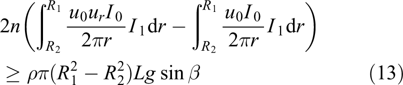
The front and back parts of equation (13) are expressed as a function of the outer radius R 1 of the magnetic drive system as

The optimal range of values for the outer radius R 1 of the model is

where M(R 2) is the nonzero intersection abscissa of functions f(R 2) and f(R 1).
According to equation (15), the optimal value of the outer radius R 1 of the magnetic drive system is not the highest possible.
Magnetic driving coil parameter analysis
The larger magnetic driving force can be obtained to drive the robot by increasing the length of the coil long side and the number of the coil windings. In this case, to prevent the current-carrying coil from leaking magnetic flux in the strong magnetic material, the enameled wire cannot be used, but instead, the bare wire nonzero distance winding method should be adopted. In addition, when the radius of the magnetic drive system is constant and the coil is not according to zero-distance winding, the coil winds may not increase indefinitely.
The magnetic drive system consists of the left and right body and the coils are arranged symmetrically. Considering the opening and closing action of the body, the coils are arranged accordingly within the range of [φ−π/2,π/2−φ], along the horizontal direction in the right body, as shown in Figure 8(a). The coil is uniformly distributed, and the arc length l within the range of angles is


Parameters of coil distribution: (a) reasonable distribution of coil windings and (b) coil zero distance distribution of windings.
Assuming the inner ring coil zero-distance winding distribution, as shown in Figure 8(b), and the central angle α corresponding to the arc between the coils a and b, according to the trigonometric function relationship, the following is obtained

where r is the coil cross-section radius.
In Figure 8(b), the arc length between the centers of the coils a and b is
The ratio k of the arc length of the effective coil arrangement on the left and right bodies of the magnetic propulsion system to the arc length between the centers of the coils a and b is

When the ideal coil is wound at zero distance, the left and right bodies can include k-windings at most. In reality, the actual coil is wound at nonzero distance, and the radius R 2 of the magnetic drive system is fixed, so the number of turns is less than k-windings.
Simulation analysis and driving force calculation theory
Establishing a simulation physical model
Based on the design and optimization of the physical model, it is proposed to instantiate the parameters to verify the correctness of the proposed model. The soft magnetic material used in the magnetic drive system is intended to be of MnZn ferrite, and its relative magnetic permeability is as high as 15,000 N/A2. Considering the cost of the material, the relative permeability is set to be u r = 1000 N/A2. As the current-carrying coil cannot withstand high-intensity current, the values I 1 = 10 A and L = 0.05 m are selected. The maximum slope present due to the sag of overhead high-voltage transmission lines generally does not exceed 40°, so setting β = 40° is a valid assumption. The magnetic drive system is composed of industrial iron, soft magnetic material, and a coil embedded with soft iron material inside. Considering comprehensively, the average density of the magnetic drive system is assumed to be ρ = 5 × 10³ kg/m3.
Since the cross-section radius of the high-voltage line is 0.02 m, the diameter of the walking wheel can be 0.02 m, satisfying the support condition of the walking wheel of the robot. Also, the closer the current-carrying wire is to the high-voltage line, the higher amperage it is subjected to. According to the actual conditions, R 2 = 0.048 m. Substituting the above values into equation (15), the optimal range of the outer radius of the drive model is

To make the body lightweight, and of smaller size, the following values are set: R 1 = 0.092 m, the coil cross-sectional radius r = 0.0015 m, and φ = 10°, as shown in Figure 8(a). According to equation (19), the number of windings of the coil around the body is up to 89, so the physical model must be established in a range of number n of coils being less than or equal to 89.
To facilitate the analysis and calculation, the coil windings connected from the head to the tail in the solid model are reduced to a single-independent coil windings. The simplified model is shown in Figure 9 (n = 10).

Simulation calculation model.
Simulation analysis
Simulations under constant number of coil windings and various high-voltage current conditions
In COMSOL, the following parameters are set: the material properties of the magnetic drive system model, the physics field as the magnetic field, the multiwinding coil, the coil type as numerical, the number of windings of each coil to one, and the coil current to 10 A. The high-voltage offline current density is set under the conditions of high-voltage currents of 500, 1000, and 1500 A, respectively. A magnetically insulated boundary surface is selected, thus, magnetic insulation boundary condition is active. Next, a coil current direction is set. The meshing mechanism uses a freely divided tetrahedral mesh of extremely high density. The model is calculated by setting the automatic calculation current and the steady-state solution is selected. The simulation sectional diagram of the coil with 10 windings, under the three different high-voltage currents, is shown in Figure 10.

Simulation section charts of the same model in different high-voltage current conditions: (a)

Sectional charts of model simulation at the same high-voltage current: (a) n = 2, (b) n = 6, (c) n = 10, (d) n = 12, (e) n = 16, and (f) n = 20.
According to the above simulation cross-sectional view, when the number of coil windings and the current of the coil remains the same, an increasing high-voltage current results in increasing strength of the surrounding magnetic field.
The COMSOL is applied to calculate the ampere-distribution force of the drive system in the x, y, and z directions of the magnetic drive system of the 10-windings coil under the conditions of high-voltage currents of 500, 1000, and 1500 A, respectively. The calculation results are provided in Table 1, where the ampere force along the z-direction is the driving force of the robot (the negative data in Table 1 indicates that the ampere force is opposite to the original positive direction).
Simulation results of the amperage force in the three-axis direction for a steady number of coil windings and various high-voltage current conditions.

Since the magnetic drive system generates magnetic coupling, and the whole model does not demonstrate uniformly symmetrical distribution, the magnetic induction line is deflected, and the magnetic drive system generates component forces in all three directions with a much larger ampere force in the z-direction than in x and y directions. Therefore, the component forces generated in the X and Y directions are negligible.
Simulation with steady high-voltage current and various number of windings
The high-voltage line current is generally 200–3000 A. Considering that the current in the actual high-voltage DC line changes significantly, the following values are considered: I 0 = 1000 A and the coil current I 1 = 10 A. Next, the magnetic driving force is calculated separately for the various number of coil windings. Specifically, the magnetic driving force is simulated for the number of coil windings: 2, 6, 10, 12, 16, and 20. Figure 11 shows a simulation cross-section of the magnetic drive system model for the various coil windings.
It is seen from the simulation diagram that the points in the inner and outer diameter of the magnetic drive system in Figure 10 are the cross-sections of the coils. Also, the magnetic field, on both sides of the cross-section of the coils, is stronger on one side and weaker on the other side. The direction of the magnetic induction line of the high-voltage line and the direction of the magnetic induction line generated by the current-carrying coil are determined by the right-hand rule. When the current direction is consistent with the latter direction, the magnetic field strength is enhanced; when the current direction is opposite to the latter direction, the magnetic field strength is weakened.
The ampere force of the different coils in the three-axes direction is calculated by COMSOL software, as provided in Table 2.
Simulation results of ampere force magnitude of windings of three coils in three axes.
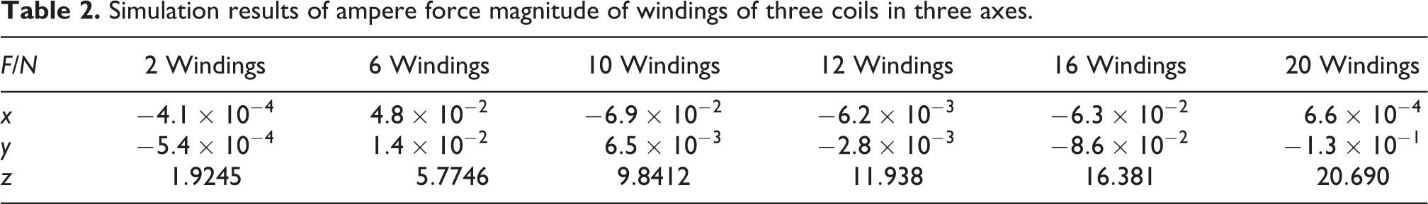
In the point graph of the relationship between the ampere force F and the number of coil windings n of the magnetic drive system, there is linear fitting by Matlab software version is 16.0, as shown in Figure 12.

Curve of ampere force versus number of coil curve.
According to the characteristics of the data, using the quadratic polynomial curve type fitting, the relationship between the amperage force and the number of coil windings is derived as

In the case of a magnetic drive system with a total of 60 coil windings symmetrically distributed on the left and right fuselage, the ampere force is given by equation (20)

Driving force calculation theory
Under the condition that the magnetic field coupling and the nonuniform symmetry factor of the material structure are not considered, the theoretical force of the magnetic drive unit, according to the model, and in the case of n = 30, is calculated as

It can be seen from equations (21) and (22) that the simulation results are very close to the theoretical calculations.
Experiment
According to the aforementioned model parameters, a suitable experimental magnetic drive device is constructed. The equipment sets employed are high current DC generator (range 0–1500 A), analog high-voltage wire, digital tension meter (range 0–500 N), magnetic drive device, inspection robot, and several other components (Figure 13). Strong magnetic material (magnetic conductivity of nonconductive) made of magnetic core is used. Sixty coil holes were drilled in the circumference of the magnetic core. Peripheral lining is made of resin material. The key parameters of the magnetic drive device based on the previous theoretical calculation assume that the relative permeability of soft magnetic material is 1000 N/A2; the inner diameter R 2 = 0.048 m, the outer diameter R 1 = 0.048 m, and the coil current I 1=10 A (powered by current source). The simulation results in the previous section assume that the coil and the magnetically conductive material are in zero-distance contact, and the simulation is performed under the premise of no magnetic flux leakage. Therefore, to minimize the leakage flux in real conditions, the coil is made of soft iron material. At the same time, after the coil passes through the hole, the same type of powder magnetic material is mixed with the epoxy resin, and after the device is cleaned and dried, it is then pressed into the coil hole to fill the hole wall between the coil and the gap. To accurately measure the actual size of the magnetic driving force, the experiment is placed in a high-voltage wire level, high-voltage wire has zero contact through the magnetic drive device bore, and the magnetic drive device is directly linked to the tension meter hook.

Experiment of magnetic drive: (a) Current generator, (b) experimental setup, (c) magnetic drive device, (d) magnetic drive measurement, (e) robot crossing clamp experiment, (f) robot spanning shockproof hammer experiment, and (g) robot straight walking experiment.
During the experiment with the currents of 100, 200, 300, 400, 500, 600, 700, 800, 900, and 1000 A in the high-voltage wire, the measured magnetic driving force is compared to the theoretical calculation values (equation (22)), and the result is shown in Figure 14. In the experiment, the magnetic driving force is consistent with the direction of gravity, and the measured value in Figure 14 is subtracted from the weight of the magnetic drive unit.

Comparison between experimental measurements and theoretical calculation of magnetic driving force.
According to the first simulation, the number of windings of the magnetic drive device is 10, and the other parameters remain the same. The currents of 500, 1000, and 1500 A are sequentially applied to the high-voltage wires. The measured magnetic driving force, the respective simulation results, and theoretical calculation values are all compared, as shown in Figure 15.

Comparison between measured values, simulated values, and calculated values of magnetic driving force.
As can be seen from Figure 14, the magnetic drive system is capable of generating a force in the direction of the high-voltage wire, thereby establishing a driving force for the inspection robot. Under the same parameters, the actual measured magnetic driving force is lower than the theoretical calculation value, which is mainly due to the fact that a small amount of pores appear locally after the powder ferrite blended by the epoxy resin is dried causing magnetic leakage. When the high-voltage current is higher than 1000 A, the magnetic driving force generated by the magnetic drive system is considerable even close to 40 N.
As can be seen from Figure 15, under the same parameters, the simulation result for the magnetic driving force is lower than the theoretical calculation value because of magnetic coupling occurring in the simulation model and the nonuniform symmetry of the material structure that causes the magnetic induction line to be deflected. As a result, a component force is generated in the X and Y directions, thereby reducing the magnetic driving force in the Z-direction.
Comparing the results of experiments 1 and 2, it can be seen that the measured value is lower than the simulated and the theoretically calculated values because the magnetic flux leakage is not considered in the simulation model. In the cases of the same current magnitude, increasing the number of coil windings can significantly increase the magnetic driving force. The experiment proves that the proposed magnetic drive model, based on high-voltage DC magnetic field, is accurate and the magnetic drive method is technically feasible. In the robot walking experiment, the robot body can pass through the insulator and the antivibration hammer smoothly after opening, which proves that the designed mechanical structure has the ability to cross obstacles, which is a basis for the practical application of the robot and further development.
Conclusion
Given the problem that the current wheel-arm inspection robot is easy to slip, the scheme of directly driving the robot using the ampere force of the energized coil in the magnetic field around the high-voltage DC conductor is proposed for the first time. According to the motion requirements of the inspection robot and the electromagnetic principle, the theoretical model of the magnetic driving force is established. It is proven by theoretical calculation that the magnetic driving force is present in the model, and then, the simulation model is used to represent the drive model. The simulation results are close to the theoretical calculation values. This proves that the proposed magnetic drive theory method is correct. A basic structure for realizing the magnetic driving force is constructed and experiments were conducted. The experimental results showed that the magnetic drive device can generate an effective force along the direction of the wire, which can be used as the power for the traction robot to move along the high-voltage wire. Because the bonding process between the coil and the magnetic core in this experiment is not refined, the magnetic flux leakage is considerable. This fault leads to nonsatisfactory experimental results, but it does not diminish the value of the experiment.
There are many ways to improve the magnetic driving force. The most important element is to improve the bonding process between the magnetic core and the coil. For example, using 3D printing or powder metallurgy sintering, the magnetic flux leakage can be minimized, thereby increasing the magnetic drive force. The proposed magnetic drive model has good scalability, while the magnetic core and the coil can be organized in a cascade manner. This way the driving force of the magnetic drive system can be greatly improved. When the minimum distance between two adjacent coils is ensured, the required magnetic driving force is acquired by increasing the number of coil windings.
Footnotes
Declaration of conflicting interests
The author(s) declared no potential conflicts of interest with respect to the research, authorship, and/or publication of this article.
Funding
The author(s) disclosed receipt of the following financial support for the research, authorship, and/or publication of this article: This work was supported by the National Natural Science Foundation of China [Grant No. 61375092] and the Hubei Science and Technology Support Program [Grant No. 2015BAA011].