
Abstract
A novel mechanism for 110 kV power transmission line inspection is presented according to the requirements of inspection tasks and characteristics of obstacles on power transmission lines. Its configuration is introduced, and the navigation process of typical obstacles is planned. Then the kinematics equations and the workspace are derived. The grade ability of the power transmission line inspection robot is analysed and then improved by some measures. The quasi-static mode of the robot and the contact mechanics of the wheels are established. Adhesion force of the driving wheel can be improved by optimizing the structure of the wheel and the wheel load is reasonably distributed by planning the posture of the robot. So the climbing ability is ameliorated. The climbing ability of the different wheel structure and the different posture is simulated. Furthermore, the simulation of the navigation of the strain clamp and test of navigation of the jumper in the laboratory have been carried out. The simulation results demonstrate that the mechanism has such characteristics as compact construction, strong stability and excellent obstacle negotiation capability.
Introduction
Transmission grids, as strategic assets, need to be operated in a safe, predictable and reliable way. Transmission line inspection is to master the operation of the line, for timely detection of defects in the power facilities and the situation along the line and to provide information for the transmission line maintenance. Compared with the traditional manual inspection, transmission line inspection robot is of low cost, safe and reliable, which can be close to the fine inspection and easy to operate and gradually becoming a new research hot topic of line inspection. 1,2 The main research interests focus on the mechanism of optimal design, the control system design, the power supply, fault detection methods, EMI/EMC and so on. Above all, it is very important to design a proper mechanism with excellent locomotion and navigation performance.
In the early 1990s, Sawada et al. 1 developed an arc-shape line inspection prototype robot. HiBot Corporation and Tokyo Institute of Technology developed a robot named Expliner 3,4 which has a carbon-fibre structure with a T-shaped base and a 2-degree of freedom (DOF) manipulator. This robot can inspect and cross the obstacles on transmission lines of 500 kV. The robot consists of two drive units, two vertical rotary joints, two 2-DOF operating arms and an electrical cabinet. Quebec Hydro Institute of Canada developed a new kind of robot LineScout. 5,6 The LineScout, which can inspect live transmission lines of 315 kV, includes three separate parts: the guide wheel frame, arm frame and centre frame. Morozovsky designed a small inspection robot SkySweeper. SkySweeper is V shaped with a motor-driven ‘elbow’ in the middle and its ends are equipped with clamps that open and close as necessary to move it down the line inch by inch. 7 Trevor Lorimer and Ed Boje designed a simple robot which is able to cross strain tower. The robot is a series of links with a gripper at each end. When one gripper is detached from the line, the robot may be thought of as a serial manipulator, with the attached gripper being the base and the detached gripper being the end effector. 8
Supported by the National High-Technology Research and Development Programme of China, the State Key Laboratory of Robotics, Shenyang Institute of Automation, Chinese Academy of Sciences, has been focusing on the development of mobile inspection robots for 500 kV extra high voltage power transmission lines (EHV-PTLs) in recent years. Some prototypes have been developed from 2002. In the first-generation robot named AApe-A, the mobile mechanisms for one span and for large inclination angle lines, the control system in the strong electromagnetic environment and the long-distance data/image transmission were implemented. In the second generation, the robot AApe-B is adjusted to roll on the overhead ground wires (OGWs) and navigate different types of obstacles in autonomy and remote control mode. References 9,10 showed the AApe in a field-oriented perspective, describing the integration of mechanical and electrical systems and the validation performed to verify its reliability.
According to the characteristics of the 110 kV transmission line environment and the requirements of inspection tasks, a novel inspection robot mechanism is presented. The novel mechanism consists of two-wheeled locomotion mechanisms, dual arms, one frame and centroid adjustment mechanism, which can move along the conductors and negotiate a variety of obstacles on the 110 kV power transmission lines. This article is organized as follows: The overview of the completed research work and the environment characteristics of 110 kV transmission line are presented in the first and second sections, respectively. Then the inspection robot configuration is introduced in the third section. Architecture and manoeuvers are planned in the fourth section. The climbing ability is analysed in the fifth section. The feasibility of the mechanism design is verified in the sixth section, followed by the conclusions in the last section.
Environment description
According to the inspection task requirements for 110 kV power transmission lines, the inspection robot needs to move along the power transmission line, navigate the obstacles and carry visible light camera and infrared camera to complete inspection tasks.
The environment of the 110 kV power transmission lines is very complicated, where there are straight towers, strain towers, conductors, OGWs, vibration damper and other electric power equipment. A general schematic of 110 kV transmission line is presented in Figure 1. There are many obstacles on conductors such as vibration dampers, suspension clamps, strain clamps and jumper. Strain towers in the transmission grid are common as they are used to change in direction because of terrain or avoidance of privately owned land. A jumper is a short length of conductor that does not sustain mechanical tension, making an electrical connection between two separate sections of a line. Jumpers at strain towers are one of the most complex obstacles on the line to traverse; they are the flexible cables that are not as stiff as main spans and have complex spatial curves. At the end of the jumper, its slopes are approximately vertical, and their layout varies considerably from tower to tower. In order to accomplish the inspection task, the robot must have the ability to navigate the obstacle around straight line tower and the strain tower.
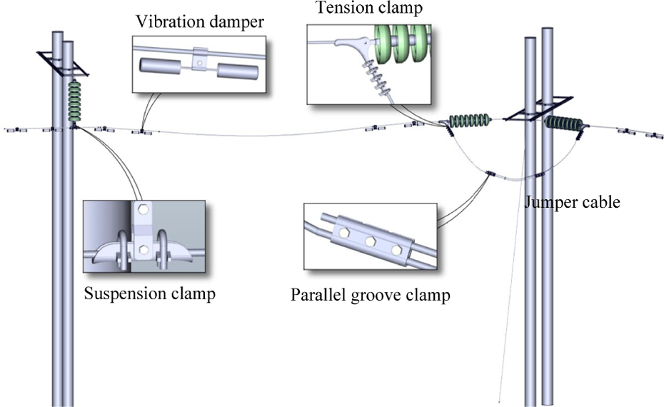
Environment schematic of 110 kV transmission line.
As shown in Figure 1, the robot should have the ability to move on the jumper since its span is very long. Because of the flexibility and un-tensioning, the posture of the jumper cable will change when the robot moves on it. Moreover, there are many different obstacles on the jumper such as strain clamps and parallel groove clamps. The robot mechanism must be of high stability and simplicity and have navigation capability. When gripping the jumper, the robot cannot damage the conductor. Because the inspection tasks are carried out on energized lines, reducing the electromagnetic effect on the performance of the robot is a very important requirement. The size of the robot should be minimized so that a safe insulation distance from ground and other circuits is maintained.
The mechanism designed for inspecting conducts should perform the inspection tasks as good as a trained human operator. Based on the requirement of the inspection tasks and the environment characteristics of 110 kV transmission lines, the mechanism should be developed with the following functions:
Moving on the conductor steadily and rapidly. Navigating different obstacles such as vibration damper, strain clamp and the jumper. Climbing a conductor at an 80° slope. Keeping stability during moving on the conductor and navigating obstacle. Compact construction.
Mechanism configuration
Figure 2 is a schematic diagram of the inspection robot. The robot consists of two-wheel locomotion mechanisms, two arms, a centroid adjustment mechanism and an electrical box component. The wheel locomotion mechanism is applied to ensure the robot can move rapidly on the conductors. Each locomotion mechanism consists of a wheel and two grippers. Each arm includes a rotation joint and two translational joints. With the help of the centroid adjustment mechanism, the body of the robot can keep horizontal, which improves the stability of navigating obstacles.
Structure schematic of robot.
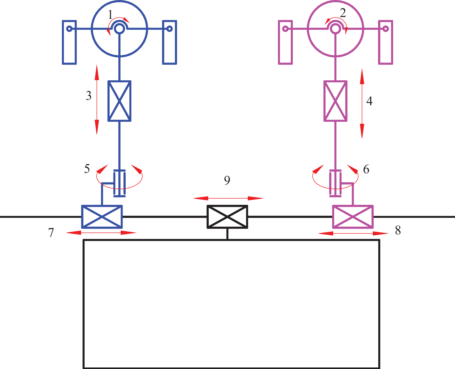
The sketch diagram of the inspection robot is shown in Figure 4. θ 1 and θ 2 are revolving joints. When the robot navigates the strain clamp, the fore gripper or the rear gripper can rotate to grasp the jumper. θ 3 and θ 4 are translational joints which provide a linear sliding movement for the forearm or the rear arm. Their functions are to go up or down for forearm and rear arm. When the forearm or the rear arm hangs on the conductor in obstacle navigation process, the rear arm or the forearm is on or off the conductor. θ 3 and θ 4 are also revolving pairs. When the forearm hangs on the conductor and the rear arm is off the conductor, the body of the inspection mechanism can rotate through the axes which are driving by the θ 5 and θ 6 and implement obstacle navigation. θ 7 and θ 8 are translational joints which drive the arm mechanism to move back and forth. θ 9 is a prismatic joint for centroid adjustment. The centre of gravity can be located under the forearm or the rear arm by intentionally actuating the robot joints when the robot is navigating obstacles. The centre of mass of the robot is always located at the bottom of the forearm or rear arm by adjusting in obstacle negotiation sequence.

Locomotion mechanism assembly diagram.

Inchworm manoeuver.
In a word, the robot can move on the conductor steadily and rapidly by using the wheeled locomotion mechanism. The wheel arm and the centroid adjustment mechanism ensure the robot has obstacles navigating ability and climbing ability.
Locomotion mechanism
The inspection robot rolls with dual wheels, when it encounters obstacles, the front arm and rear arm rotate alternately and negotiate them. For safe reliability, the clamping jaws must fasten when single arm hangs on the conductor. Therefore, a novel locomotion mechanism is designed, as shown in Figure 5.

Brachiation manoeuver.
The principle of the locomotion mechanism is as follows: When inspection robot is running, the running wheel 9 is rotated driven by the running servo motor 2. The friction force between the running wheel and conductors drives inspection robot to run. For increasing the friction force, the contacting section of the running wheel adopts polyurethane material; meanwhile, the base of the running wheel adopts steel material. The running wheel is installed on axle 4. The running wheel is mounted in axial direction with two anti-thrust bearings 3 and fastened on the bidirectional screw by the round nut 11. The fore clamping 5 and the rear clamping 13 are clamped or unclamped through the differential 5 driven by the gripping servo motor 7. With the help of the differential 5, the fore clamp and the rear clamp can clamp different diameter conductors separately. In Figure 3, the solid line denotes the limit position of the clamping jaws in unclamping state, and the dash line denotes the position of the clamping jaws in clamping state.
Centroid adjustment mechanism
The centroid adjustment mechanism is a strategic system of the robot mechanism since it generates the movement of the two arms and box. The centroid of the robot can be adjusted by adjusting the position of the arm and the electric box on the guide rail. Two arms and electric box are driven by three synchronous belts.
Architecture and manoeuvres
Navigation manoeuvres
According to the configuration of the developed inspection robot, the process of obstacle navigation can be realized by two modes, namely, brachiation mode and cankerworm mode. For the obstacles such as counterweight, the inspection robot can navigate the obstacles by lifting the fore/rear arms in turn in the cankerworm mode. For the obstacles like clamps, since the fore/rear grippers cannot pass over the obstacles even though the fore/rear arms had been lifted to the maximal range, the obstacle navigation is carried out in the rotate mode. Taking a jumper obstacle as an example, the detailed descriptions of the two obstacle navigation modes are as follows. 11
Obstacle navigation in the inchworm mode
As shown in Figure 4, when the inspection robot encounters a counterweight obstacle, the process of obstacle navigation in the inchworm mode is given as follows: step 1: The robot has both wheels on the conductor, the rear clamp grasps the conductor, arm extents until it is higher than the counterweight obstacle; step 2: By rotating the forearm , the rear one will cross over the obstacle; step 3: With the camera mounted on the rear gripper, the OGWs is located and the rear arm is controlled to grasp the ground wire behind the navigated obstacle. Hence, the inspection robot can navigate obstacles by rotating the two arms and repeating the above steps.
Obstacle navigation in the cankerworm mode
As shown in Figure 5, when the inspection robot encounters a counterweight obstacle, the process of obstacle navigation in cankerworm mode is described as follows: step 1: The forearm extents until it is higher than the counterweight obstacle; step 2: The rear arm drives the robot moving forward until the rear one encounters the counterweight obstacle. Hence, the forearm is behind the obstacle. Step 3: With the camera mounted on the forearm, the OGWs are located, and the forearm is controlled to grasp the ground wire behind the navigated obstacle. The inspection robot can navigate obstacles by lifting the two arms and repeating the above steps.
Both of the two modes have their advantages and disadvantages. Obstacle navigation in the cankerworm mode is time-saving, but it is easy to be interfered by the ambient environment like the wind or vibration of the OGWs, since it has to drive the robot moving forward with only one arm on line. On the contrary, the obstacle navigation in the rotate mode is stable, but it spends more time in navigating obstacles than that in the cankerworm mode. This is because both of the two arms should be rotated alternatively.
Kinematics
When the mechanism needs to navigate the obstacle, the gripper of the arm should grasp the conductor. When one gripper is detached from the line, the mechanism may be thought as a serial manipulator, with the attached gripper being the base and the detached gripper being the end effector. The gripper plays a fixed role in the obstacle negotiation sequence, so the freedom of the wheel and the gripper should be neglected in the kinematics modelling. The centroid must be adjusted to the attached arm which can improve stability of the navigation and decrease the deformation of jumper during the whole process. The joint θ 1 or θ 2 on the attached arm is locked when the robot navigates obstacles. The distance of height between two locomotion mechanisms is adjusted by the joints θ 3 and θ 4. So only one freedom exists in joints θ 3 and θ 4. The function of θ 7 and θ 8 is to adjust the distance between two arms. Joints θ7 and θ8 can be equivalent to one degree of freedom.
The mechanism has 5 DOF in total, where joints 1 and 3 are perpendicularly translation joints and the other three are rotating joints on both arms. The coordinate system of each link is formed as shown in Figure 6, and based on Denavit-Hartenberg method, robot link parameters are obtained. Link parameters of inspection robot are shown in Table 1 where specific values of link parameters are not listed. We can derive the kinematics of the mechanism by matrix multiplication of the individual link matrices
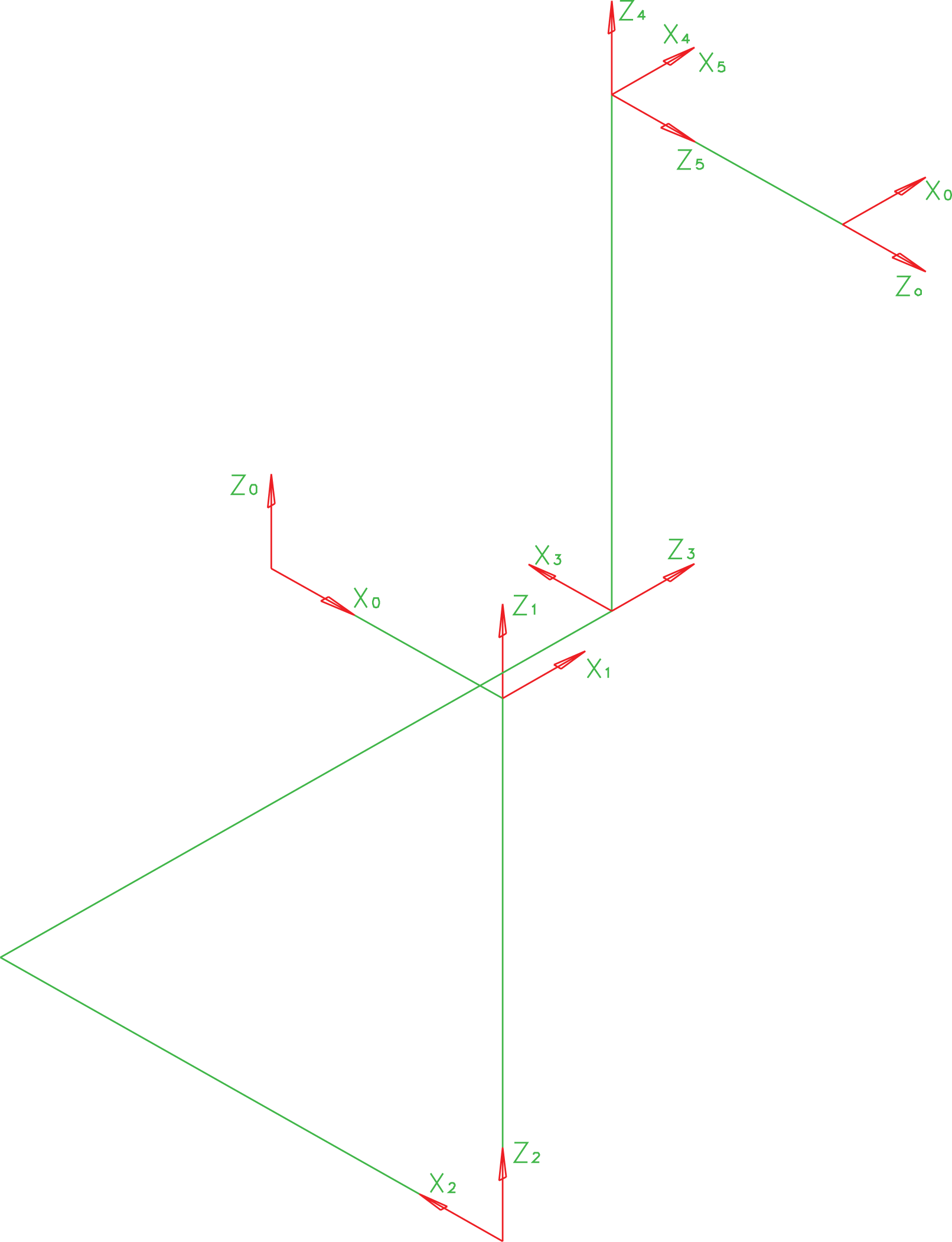
D-H coordinates and link variable parameters. D-H: Denavit-Hartenberg.
Denavit-Hartenberg parameters of the robot.

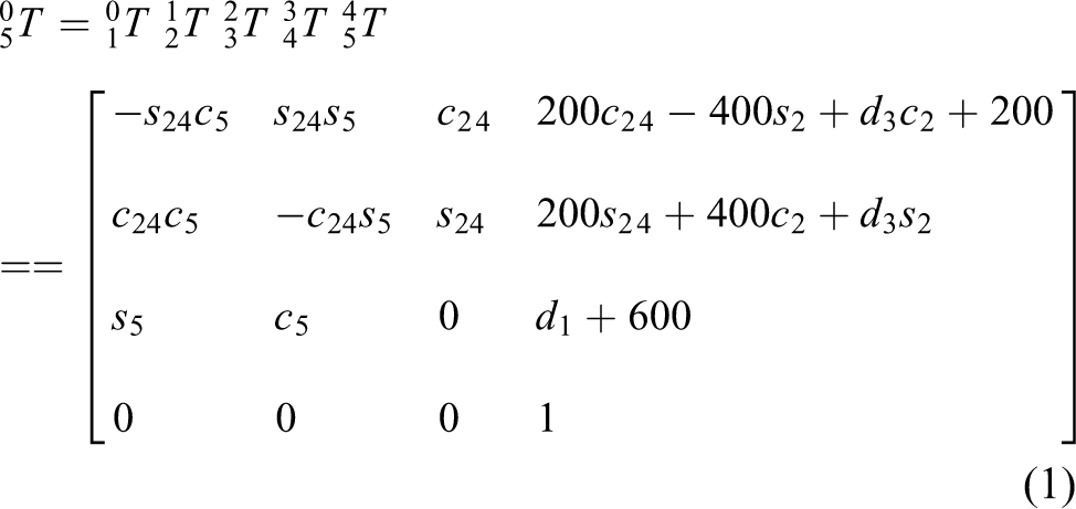
Inverse kinematics is computed using a geometrical approach 12 ; it is possible to decouple the inverse kinematics problem into two simpler problems known, respectively, as inverse position kinematics and inverse orientation kinematics. First, the position of the intersection of the wrist axes has to be found, hereafter called the wrist centre, and then finding the orientation of the wrist. The inverse position kinematics is

Navigation process
According to the analysis of 110 kV transmission line environment, jumpers represent the most challenging type of line to traverse. The process of jumper navigation can be divided into five stages which is shown in Figure 7. So, the process of navigating strain clamps is planned as a typical representative of obstacle negotiation process which is shown in Figure 8. Taking a jumper obstacle as an example, the detailed descriptions of the obstacle navigation sequence are as follows:
The robot stops in front of the obstacle to cross. The gripper of the forearm clamps firmly onto the conductor from above to secure the robot. The electrical box slides forward so that the centre of gravity of the mechanism is now located below the forearm. Then, the rear arm extends until it is higher than the strain clamp; the rear arm rotates to move the rear locomotion mechanism away from the conductor. The rear arm and forearm swing to move the rear locomotion mechanism close to the jumper. The electrical box slides backward so that the centre of gravity of the mechanism is still located below the forearm. The rear arm rotates to bring the rear gripper into alignment with the jumper, and the gripper clamps onto it, providing a new set of supports for the robot. The gripper of the forearm releases and is moved away from the conductor. The rear and forearms swing to move the fore locomotion mechanism close to the jumper. The forearm rotates to bring the fore gripper into alignment with the jumper, and the gripper clamps onto it.

The diagram of jumper sections.
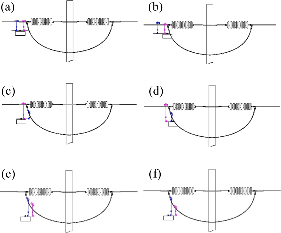
Process of navigating jumper.
Analysis of the climbing ability
There are many power transmission lines distributed in the mountain or crossed the big river, so the robot should have the ability to roll on the large angle lines. Adhesion force of the driving wheel can be improved by optimizing the structure of the wheel, and the wheel load is reasonably distributed by planning the posture of the robot.
Hypothesized wheel–conductor interface behaviour
The power transmission line is now generically moved by wheels that can increase the speed of inspection. The cross section of the contact of the wheel and line is mostly circular. Because the line is the aluminium conductor steel reinforced, the circular wheel can fit tight to the lines. In order to adapt to different radius lines, the wheel section is adjusted to the middle groove.
By inspecting more closely the circled area of contact in Figure 9 (b), a simplified static traction model is proposed. It assumes a linear patch of contact, of width 2α onto which is applied a linear pressure field Fn . The load of the wheel is W, thus
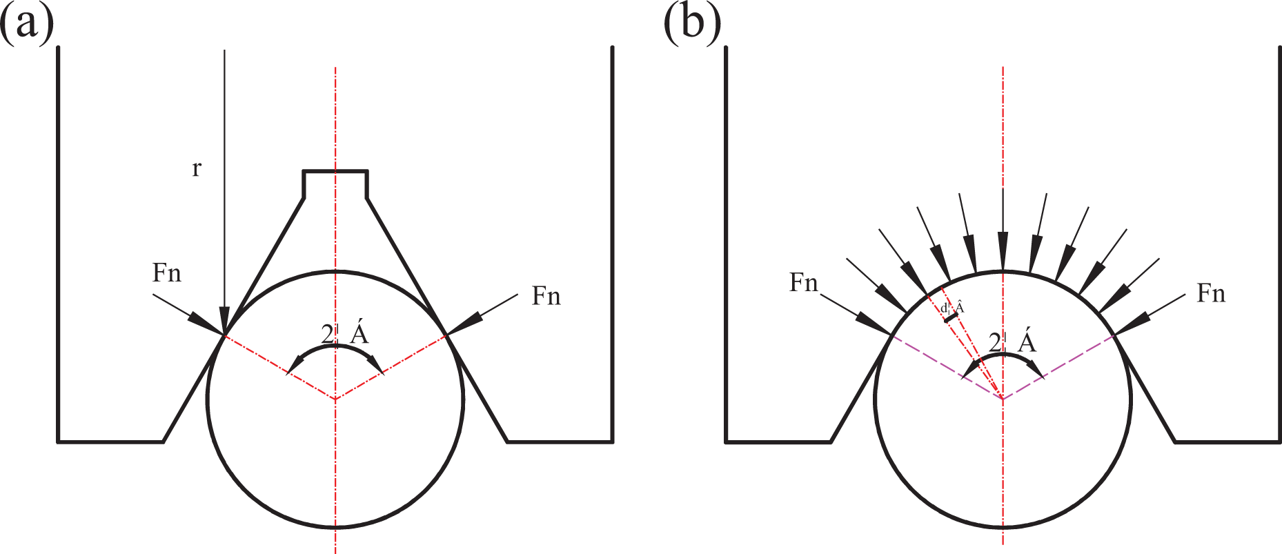
Hypothesized wheel–conductor interface behaviour.
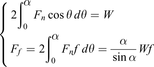
If the wheel section is the middle groove, the relation of the load w and the friction F′ f can be calculated as follows

A comparison of the results obtained by these two structures will yield additional insights.

The friction of the groove wheel is always greater than the friction of the circular wheel.
The quasi-static mode of the robot
According to the requirement of the inspection task, the inspection robot can run on the power transmission lines autonomously and inspect the transmission lines, towers, the passing way, the power grid crossings and other devices using visible or infrared thermal imaging cameras and other equipment. The robot’s usual means of travel is to roll on two wheels supported by the conductor. When the robot needs to navigate the obstacles, the robot can be driven by one wheel. Mechanical model of driving wheel of two wheels supported by the conductor is shown in Figure 10. Because the distance between two arms is much less than the curvature radius of the transmission lines, the line between can be simplified into a straight line. 12

Mechanical model of driving wheel.
Because the inspection speed of the robot is slow, the damp can be omitted. Assuming the starting or stopping acceleration of the robot as a, the dynamic model is as follows


where Mf and Mb are the rolling friction couple of the fore and rear wheels, respectively, Md is the drive torque of the fore wheel, m is the weight of the robot, Ff and Fb are the friction of the fore and rear wheels, respectively, Nf and Nb are the positive pressure of the fore and rear wheels, respectively, δ b and δ f are the coefficients of rolling friction of the fore and rear wheels, respectively, and f is the coefficient of rolling friction of drive wheel.
Overall, the following relation must be maintained

In order to assure the resistance to skidding, the friction of two wheels should match the following

The posture planning
According to the quasi-static mode of the robot, the maximum climbing angle can be calculated when the output torque and the load of the driving wheel are known. According to the inspection technical requirement, the robot rolling velocity v is 0.5 m/s, the wheel radius

Posture of the robot: (a) the original posture and (b) the adjusted posture.
This can be simplified to find the following relation:
Simplified motion control model, set joint 4 don’t exercise, only joints 2 and 3 work, so the speed of each joint can be derived:

If the two walking wheels were equal to the load, the robot centre of mass should be at the centre of the two arms on the horizontal direction; because the two arms are equal in quality, through the centroid adjustment joint drive electric box to adjust the robot centre of mass to the centre of two arms, to guide the quality, for the quality of the electrical box, the centroid adjustment joint exist with the following relations.
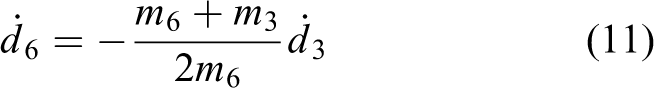
When the centre of the robot mass is located in the centre of two arms, the load of two wheels is equal. Because the two arms are same, the centre of the robot mass can be adjusted though the centroid adjustment joint. m3 is the mass of guide, m6 is the mass of box, so the relation of joints can be calculated as follows:

So the velocity of centroid adjustment joint
The robot rolling on different angle lines is simulated in ADAMS (Adams 2014), according to the joint planned joint curve. The simulation conditions are as follows: simulation time is 26 s, the number of simulation step is 3000, and the mass of robot is 35 kg, and joint 1, joint 4 and joint 5 are in passive state.
When the posture of the robot is not planning, the torque of two driving motors increases as the incline angle of the transmission lines increases; and when the incline angle is greater than 11°, the torque of the front wheel decreases as the incline angle increases as shown in Figure 12. Although the front wheel supports the most load of the robot, the maximum robot climbing angle is 14°. Because of the various distribution of weight, the robot cannot get the most out of the two wheels. By planning the posture of the robot, the weight of the robot can be uniformly distributed to the two wheels. In Figure 10, the maximum climbing angle is 24°.
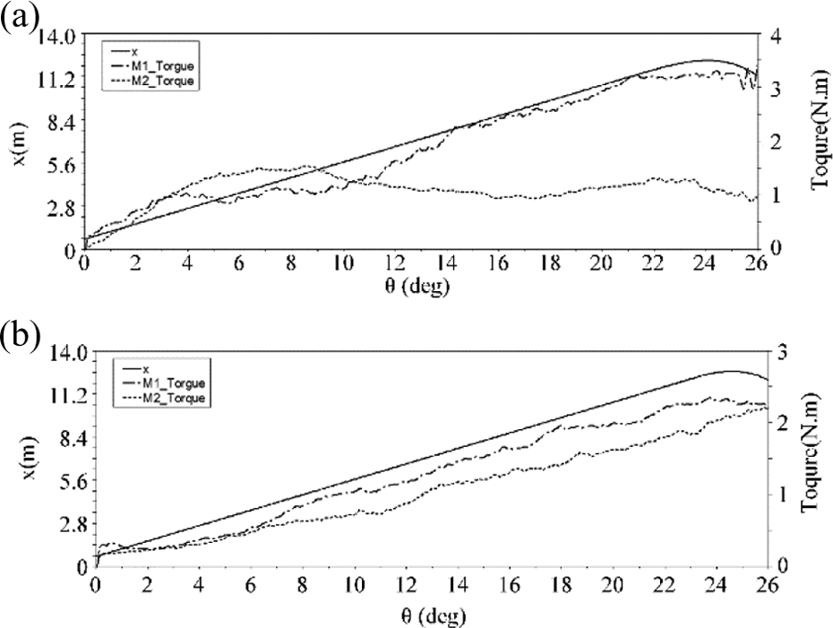
The curves of climbing ability and driving torque: (a) the original posture and (b) the adjusted posture.
Mechanism design verification
In order to prove the correctness of the method proposed, we simulate the environment of the ultra-high voltage power transmission lines in the lab. There are two counterweights, single overhang anchor clamps, and a jump and two strain clamps in the environment (see Figure 13a).

Robot rolling experiments on power lines with large angle: (a) environment, (b) 15° angle, and (c) roll on the incline line.
The maximum climbing angle is tested though the robot roll on the different angle lines. The robot can roll on the line whose incline angle is 15° (Figure 13b), then the incline angle of line is increased to 20° (Figure 13c), the robot skidded and can’t continue to climb up, then the posture of robot is adjusted according to the algorithms mentioned above. When the angle of line is 22°, the robot skidded again.
Because the transmission line conductor is the aluminium conductor steel reinforced, there are a lot of grooves on the surface, so the actual contact area is less than the simulation environment and the maximum climbing angle of robot is only 20°. The test results show that the maximum climbing angle can be improved by adjusting the robot posture.
Then we test the ability of navigating obstacles in the lab. Figure 14(a) denotes that inspection robot encounters the clamp and stops on the conduct. The electrical box is moved over the forearm. The rear arm is up and off the conduct and navigated the clamp, then down and on the jumper (see Figure 14b). Then the electrical box is moved over the rear arm, the forearm is up and off OGWs. Next, the forearm navigates the strain clamp and is down and on the jumper (see Figure 14c). Repeating the above steps, the inspection robot can navigate the strain clamp and the jumper.

The process of obstacles negotiating.
In order to qualify the mechanism, field deployment of the robot has started on a trial basis in 2016. The robot can navigate the suspension clamp (Figure 15a) and the vibration damper (Figure 15b).

Robot deployed over forest-crossing circuits.
The results of the experiments show that:
– The robot can navigate many obstacles such as strain clamps, jumpers and counterweights. – Adjusting robot posture can improve the climbing angle.
Conclusions
In this article, an autonomous obstacle negotiating inspection robot for 110 kV power transmission lines is introduced. The inspection robot can roll on the 110 kV power transmission lines autonomously, and navigate counterweights, clamps and other obstacles in remote control and local autonomy mode. The inspection robot can inspect the transmission lines, towers, the passing way, the power grid crossings and other devices using visible or infrared thermal imaging cameras and other equipment. The prototype robot experiments in the laboratory environment have verified the feasibility of the proposed mechanism. Adhesion force of the driving wheel can be improved by optimizing the structure of the wheel, and the wheel load is reasonably distributed by planning the posture of the robot. The simulation results show that maximum climbing angle is 24°. Eventually, the process of obstacles negotiating is brought forth through the experiments. From the experiments, we find that the centroid adjustment method proposed and the control strategy presented are feasible. The inspection robot can implement autonomous obstacles negotiating.
Footnotes
Authors’ note
Xiang Yue is also affiliated with the University of Chinese Academy of Sciences, Beijing, 100049, PR China.
Declaration of conflicting interests
The author(s) declared no potential conflicts of interest with respect to the research, authorship, and/or publication of this article.
Funding
The author(s) received no financial support for the research, authorship, and/or publication of this article.