
Abstract
Among permissible magnetic resonance imaging (MRI) compatible actuators for surgical robots, turbine-based pneumatic motors are noticeably favorited due to its compact size, simpler structure, fast additively manufacturability, and continuous bidirectional motion ability. Yet, the system dynamics of pneumatic motors, especially pneumatic nonlinearity, is often neglected and simple PID control is used, resulting in low system bandwidth (~0.5 Hz). To tackle this obstacle, this paper proposes a model-based nonlinear control method for MRI-compatible pneumatic motors. Dynamic models for a pneumatic motor previously designed by the author are developed first, followed by establishment of the nonlinear feedback controller. An error based Lyapunov candidate function is designed and mathematically proved to be globally uniformly asymptotically stable, guaranteeing desired accuracy. Experiment control tests demonstrate that the proposed control method can achieve satisfactorily better tracking accuracy than a conventional model-independent PID controller with respect to amplitude attenuation and phase delay.
Keywords
Introduction
Magnetic resonance imaging technology utilizes generated magnetic field to produce clear and real-time soft tissuing 3D images, without jeopardizing physicians or patients under ionizing radiation exposure or contrast agent usage. It is considered safer and functionally better compared with X-ray and CT scan. 1 Robot assisted minimal invasive surgery guided by MRI is therefore proposed and attracts numerous researchers into the study of MRI compatible actuators/robots design and control. Yet, MRI comes with the cost that the surgical devices made of ferromagnetic materials cannot be used within MR scanners, preventing potential danger or imaging equality degradation. The U.S. Food and Drug Administration (FDA) 2 and the American Society for Testing and Materials (ASTM) 3 have strictly defined MRI-compatible and MRI-safe materials and actuation methods. Hence, existing commercially available advanced surgical robots such as Da Vinci® cannot be directly used within MR scanners. To realize advanced MRI guided surgical robots, it is vital to design MRI compatible robot joint actuators and corresponding precise control algorithm while considering the surgical safety and accuracy requirements. 4
Compared with hydraulic actuators, 5 ultrasonic motor actuators, 6 cable driven actuators, 7 and shape memory alloy actuators, 8 pneumatic actuators possess appealing advantages in higher sterility and safety, leading to wide studies and applications in the field of MRI guided robots. 9 Based on the architecture and working principle, MRI-compatible pneumatic actuators can be classified into piston cylinders, 10 gear step motors,11,12 turbine motors,13,14 and deformation actuators. 15 Pneumatic piston cylinders, as the most common pneumatic actuators, are extensively studied and used to construct MRI guided surgical robots. In terms of actuator control under MR environment, Barth et al. proposed a Lyapunov pressure observer based on the cylinder system energy, which eliminated the need of pressure sensor installation near the two chambers of a piston cylinder. 16 A sliding mode controller was designed to achieve servo control of the piston cylinder actuator. Note that this method did not consider the impact of the long transmission air hoses which were necessary for the MR environment, and it only had high control accuracy for input control below 0.5 Hz. To address this issue, Turkseven and Ueda fully considered the influence of long transmission air hoses and the restriction of pressure sensors under MR environment. They proposed a cylinder pressure observer based on position and force feedback, which realized accurate force control and impedance control of a pneumatic piston-based MRI rehab robot. 17 A multi-surface sliding controller based on nonlinear pneumatic system dynamics was proposed by Turkseven and Ueda later and it was compared with a traditional sliding surface controller, showing an improvement of 75% force control accuracy. 18 Other effective control methods were studied and proposed to advance the control performance of pneumatic piston-actuated MRI-compatible robots. However, as the pneumatic piston is a prismatic joint, robots built upon these actuators are inevitably cumbersome, thus impairing the surgical working space within MR scanners.
Gear-based pneumatic step motor stands itself out among pneumatic actuators under MR environment due to its compact size, rotary motion ability, fast manufacturability, and medical sterility. Stoianovici et al. invented the first MRI-compatible gear-based pneumatic step motor PneuStep. 11 The working principle is similar to that of a radial piston motor, where periodical air pressure drives three crank mechanisms disturbed at 120-degree intervals to push the central shaft to rotate. Sajima et al. proposed a more compact pneumatic step motor. 12 But it is only capable of generating unidirectional fixed step-size motion. Groenhuis et al. refined the working architecture and proposed a dual-speed pneumatic step motor, 19 which was based on pneumatically driven pistons with gear teeth to drive a rack. A noteworthy feature of this actuator is bidirectional motion ability. However, due to the fixed step-size motion of this kind of actuator, no velocity or torque control is functionally achievable. On the other hand, the position control method is relatively simple. It only needs to provide periodic air pressure to push the step motor to rotate. With the aid of built-in compatible angular position sensor to close the control loop, high-precision position control can therefore be achieved. 4
Turbine-based pneumatic motors were proposed recently to generate continuous bidirectional rotary motion ability.13,14 A turbine rotates under air pressure and outputs bidirectional continuous rotating motion/torque through a speed reduction mechanism, which is functionally similar to a brushless DC motor for robot revolute joints, as shown in Figure 1. This type of actuator has modular design characteristics and can adjust the speed reduction ratio according to different speed/torque requirements. However, the only MRI-compatible robots for MRI guided surgery20,21 (developed from the author’s previous lab) built upon a turbine-based pneumatic motor 13 ignores the dynamic characteristics of the entire pneumatic system. These systems rely on the friction and damping induced by the speed reduction modules from the pneumatic motors to halt rapidly, and therefore can only achieve position control at low frequencies using conventional model-independent PID controllers. 13 For position control at slightly higher frequencies, or force control and impedance control, more accurate system dynamic models and corresponding control methods are required. To the best knowledge of the author, there is no viable control method in the literature for the turbine-based MRI-compatible pneumatic motor to fully utilize its capacity. Some related works for high pressure vane-type pneumatic motor exist. Classical controllers such as sliding model control 22 and backstepping control 23 were proposed for vane-type air motor motion control. To further improve the control performance, Wang et al. modeled the vane motor as two nonlinear affine subsystems and designed a deterministic controller. 24 Satisfactory speed control performance was mathematically proved and experimentally tested. Hwang et al. proposed a model reference adaptive controller to resolve the hysteresis and dead band issues for vane motor control. 25 Yet, the tracking performance is only satisfactory at high frequency, thus not applicable to be used for surgical robots where slow and steady motions are more critical. Chen and Gong designed an observation-based adaptive dynamic sliding mode controller, which incorporated the robustness of the dynamic sliding mode controller and the fast online learning ability from a PID-based neural network. 26 Zhang et al. applied model predictive control method to control a sensorless vane-type joint for robots working under high voltage environment. 27 But the control accuracy is not satisfactory, especially for surgical applications. Although slightly similar, a turbine-based air motor is structurally different from a vane-type air motor, which consists of a cylindrical stator and an eccentric rotor with grooves for multiple vanes to slide in and out. The kidney-shaped spaces created in between are filled with pressurized air. As the compressed air expands, the pressure energy subsequently transforms into kinetic energy, thereby producing the rotary motion. Note that a noticeable amount of energy is lost as heat because those vanes continuously contact and slide against the stator’s surface. On the other hand, a turbine simply spins due to the force of air flow. Gaps exist between the turbine and the stator, allowing gas exhaustion into ambient environment. Therefore, direct usage of the above control methods onto turbine-based pneumatic motors is not applicable.
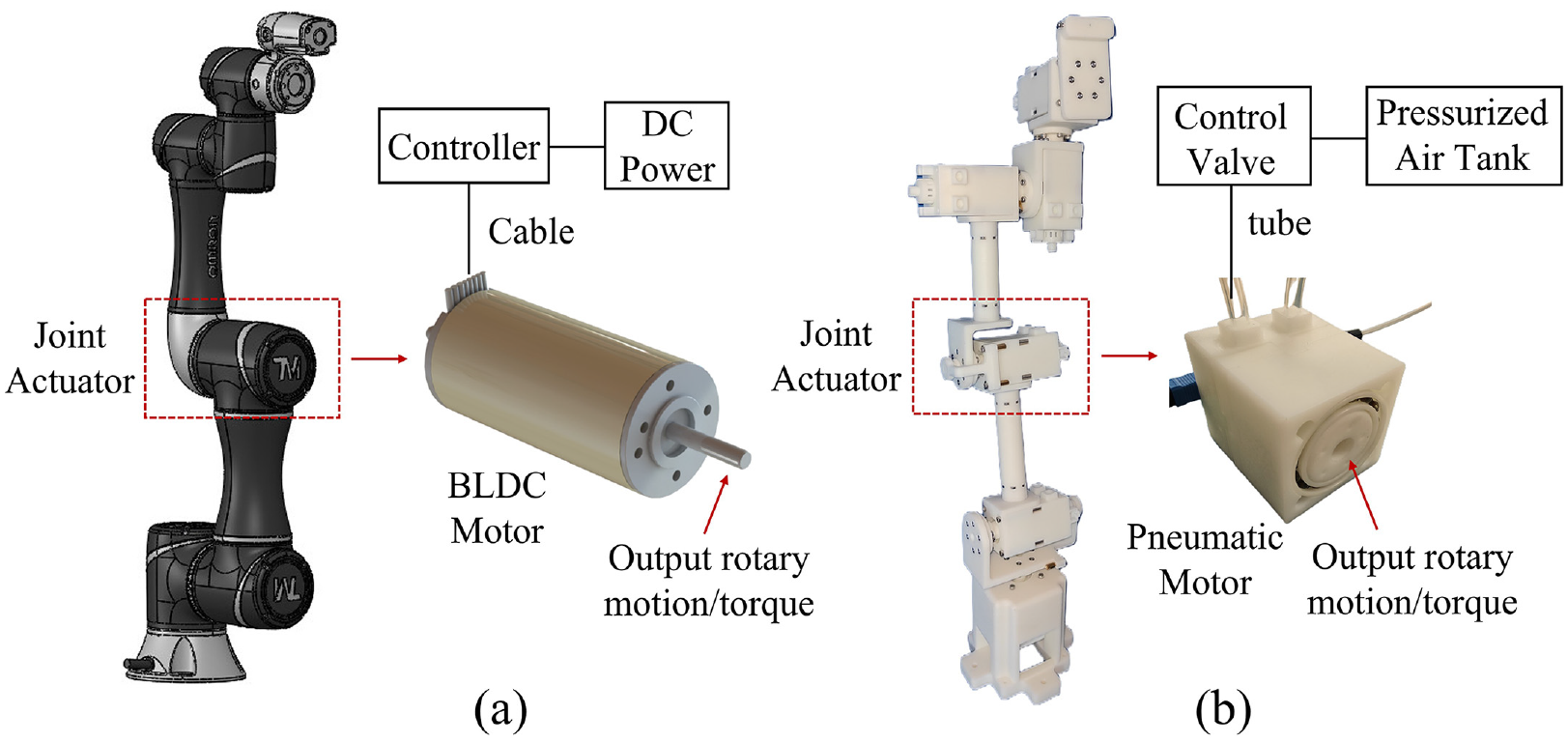
(a) Joint actuators of conventional robots based on BLDC motors and (b) joint actuators of MRI-compatible robots based on turbine-based pneumatic motors.
Conclusively, most of the research on pneumatic actuators under MR environment has focused on piston cylinders, which can achieve satisfactory position and force control with recent works. However, MRI guided robots based on piston cylinders possess a large volume, affecting surgical working space inside MR scanners. Pneumatic gear-based step motors are compact and small in size but can only output motion with fixed step size. Therefore, the constructed surgical robots can only achieve position control. Compared with the first two types of pneumatic actuators, the continuously rotatory turbine-type pneumatic motor overcomes the disadvantages and retains advantages of compactness and continuous bidirectional rotary ability. Yet, it lacks effective controllers for this type of MRI compatible actuator to fully utilize its capacity. Hence, this work aims to tackle the aforementioned issues and to promote the operating accuracy and speed. The contributions are summarized as follows:
The dynamic model of a turbine type MRI-compatible motor is established, laying the foundation for controller design.
A model-based nonlinear feedback speed controller is designed and mathematically proved to be globally uniformly asymptotically stable.
Control performance is evaluated and compared with a classical model-independent PID controller, demonstrating straightforward control improvements.
The rest of the paper is arranged as follows. Section 2 develops system dynamic models of an MRI-compatible pneumatic motor designed previously by the author to function as revolute joints for surgical robots. Section 3 presents the design of a model-based nonlinear feedback controller for the pneumatic motor, followed by stable analysis using well established nonlinear system theories. A motion error based Lyapunov candidate function is designed and mathematically proved to be globally uniformly asymptotically stable. Section 4 establishes bench top experiment tests to evaluate the proposed control method and compares it with a conventional model-independent PID controller as well. Discussion follows in Section 5 and Section 6 draws concluding remarks.
Pneumatic motor system
In this study, the author developed and tested a novel MRI-compatible pneumatic motor designed to function as a revolute joint for surgical robots. 28 The pneumatic motor produces bidirectional rotation and torque when pressurized air flow is supplied, and incorporates a multiple-blade turbine and soft strain wave gear box to convert pneumatic energy into mechanical energy. The motor is manufactured through fast additive technology, using either 3D-printable or standard mechanical components. To address the issue of inaccessible joint information within MR scanners, the motor is equipped with an MRI-compatible rotary encoder based on optical fiber wires. Detailed design specifications and motor performance evaluations are presented in Li et al., 14 and the general structure of the motor is depicted in Figure 2.
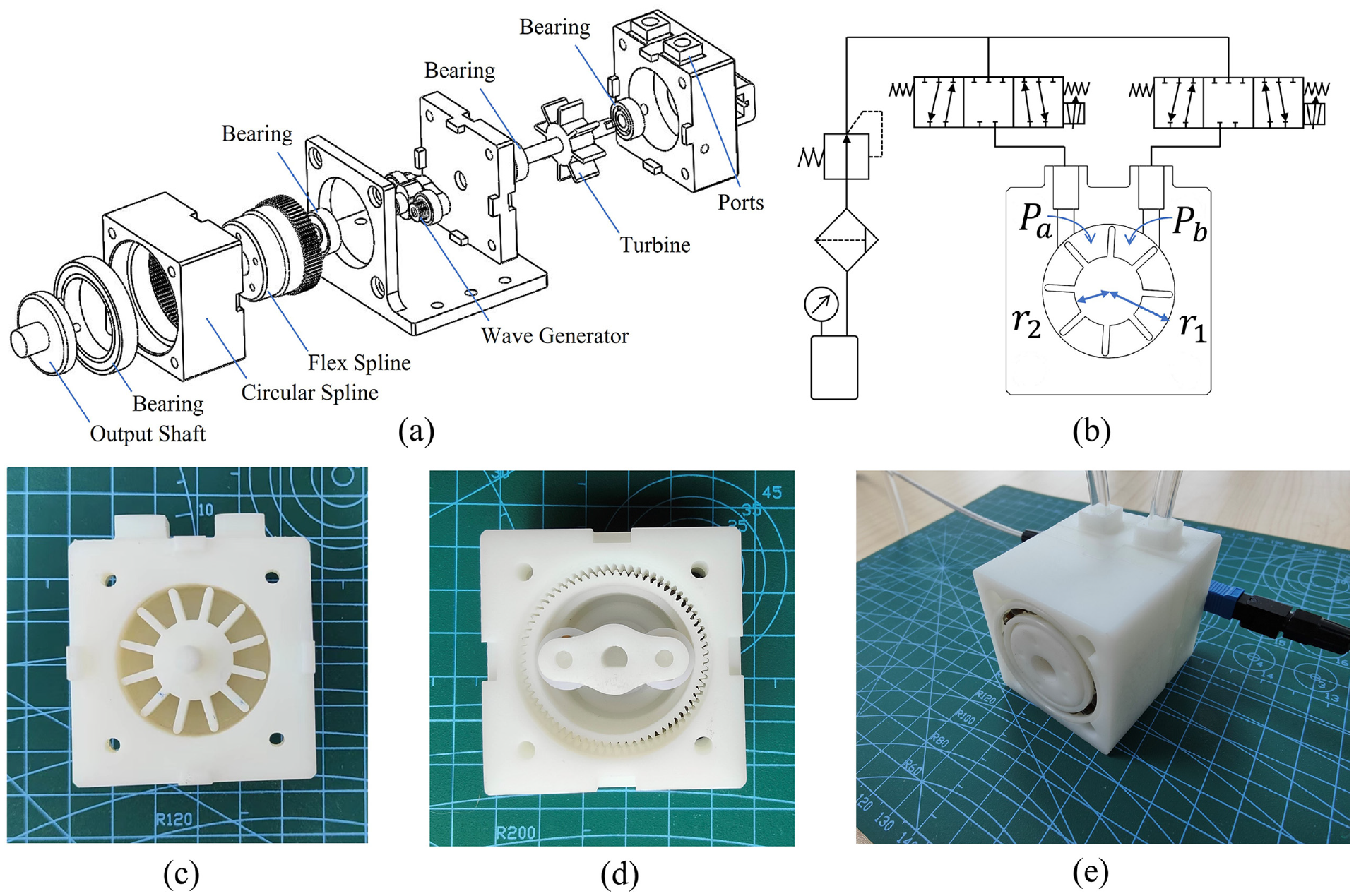
General structure of the proposed MRI-compatible pneumatic motor: (a) exploded view, (b) detailed model of the multiple-blade turbine mechanism, (c) photo of the turbine side, (d) photo of the strain wave speed reduction side, and (e) photo of the prototype.
Dynamic model of the MRI-compatible pneumatic motor
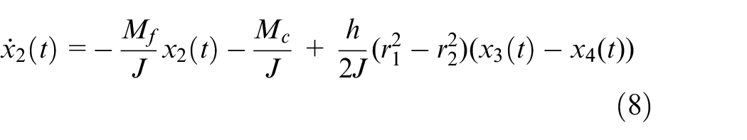
The working principle of an MRI-compatible pneumatic motor is straightforward. Pressurized air from supply source pushes a turbine to rotate and dissipates from exhaust ports into the ambient environment, without any safety or sterility concerns. A speed reduction mechanism then increases output torque and decreases speed according to different speed/torque requirements. The dynamic relationship between torque and angular motion of the pneumatic motor is established using Newton’s second law:

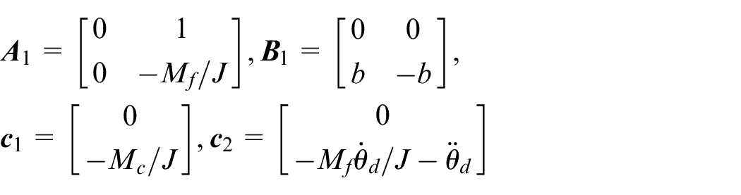
where J is the moment of inertial,

where
where
Proportional Valve Model
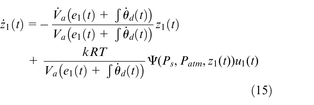
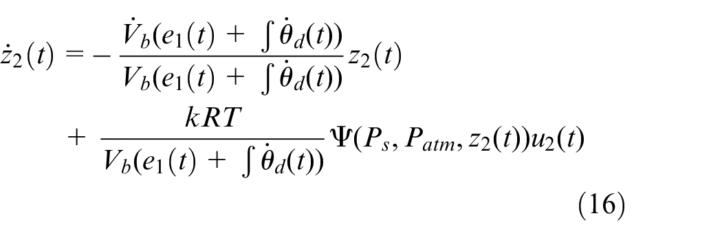
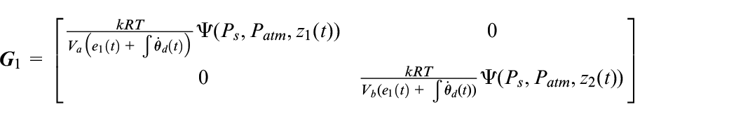
The pressure within each CV is affected by the mass flow rate flows through the orifice of proportional valves, which is well studied and modeled as an ideal gas through a frictionless orifice assuming isotropic process 31 :

where
The valve orifice area normalized mass flow rate
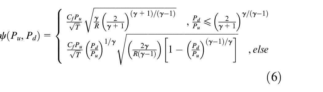
where
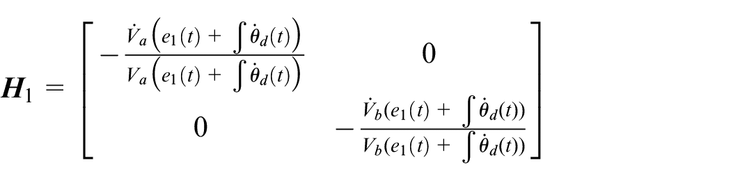
System State Space Model
Consider the previously developed equations, a state space model capturing the dynamics of the MRI-compatible pneumatic motor can be described as:

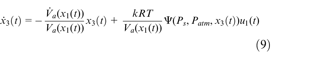
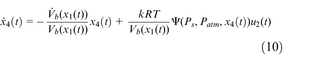
where
State Space Servo Control Model
For a brushless direct current motor serving as a revolute joint in conventional robots, a velocity control loop is normally designed for the joint to follow a desired angular velocity profile. Similarly, it is desired that an MRI-compatible pneumatic motor is capable of following a commanded angular velocity profile

Denote

which can be rearranged into a more compact fashion, denoting


where

Nonlinear controller for the MRI-compatible pneumatic motor
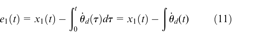
For an MRI-compatible pneumatic motor to accurately track commanded angular velocity profile, it is desired for position tracking error
State feedback controller design
A state feedback module

Design

Define a new variable
Since the orifice opening areas are controlled, the variable
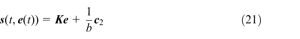
Denote
where

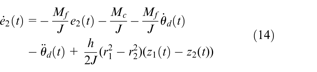
Differentiate the error,
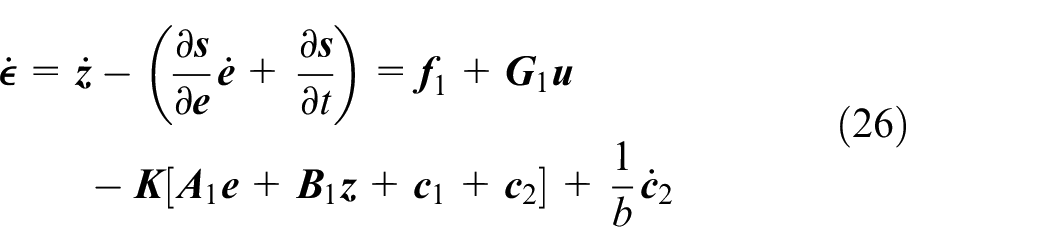
A state space control model for variables
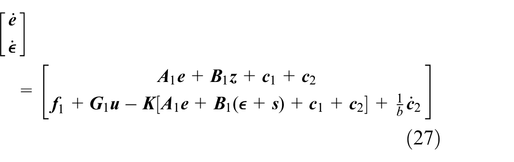
Controlled system stability analysis
To analyze the stability of the controlled system, define a Lyapunov candidate function based on the motion error state variables
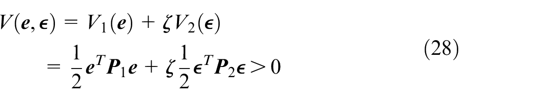
which is a positive definite quadratic equation. Take the derivative of the above Lyapunov candidate function along V with respect to time (skipped steps are derived with details in the Appendix):
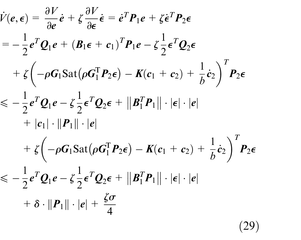
where
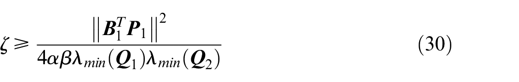
Use the inequality of
The above result indicates that if the motion error variables
Mathematically, the following theorem can be developed based on the above derived results.
is globally uniformly asymptotically stable. 33
The proposed Theorem guarantees a certain level of control precision, which is dependent on the size of the compact set
Control performance evaluation
To assess the efficacy of the proposed nonlinear controller for an MRI-compatible pneumatic motor as a viable revolute joint for surgical robots under MRI guidance, an experimental prototype was fabricated, tested, and compared to a classical model-independent PID controller.
Experimental setup
The schematic diagram of the experimental setup is illustrated in Figure 3. The pneumatic motor was connected to a multifunctional rotary/torque sensor (DYload, DYN-200, Max. 1 Nm) which provides rotary speed and torque information. Two pressure transducers (SMC, PSE530-R06, Max. 1.0 MPa) were placed right next to the two ports of the pneumatic motor via two Tee-connectors. Two 5/3 directional proportional solenoid pneumatic valves (SMC, SY3320-5LZ-M5, Max. 0.7 MPa) were used to control the variable orifice areas, thus the mass flow rate. All of the data was read and collected with a NI DAQ board (National Instruments, PCIe-6343) with a sampling rate of 1 kHz.
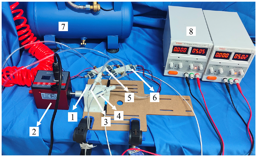
Control test setup: (1) MRI-compatible pneumatic motor prototype, (2) multifunctional rotary/torque sensor (3) and (4) pressure transducers, (5) and (6) directional proportional solenoid pneumatic valves, (7) pressurized air source, and (8) power supplies.
Pneumatic motor control test
A series of sinusoidal angular velocity command signals
The control diagram structure for the proposed model-based nonlinear controller is a cascade of systems equations (17) and (18) using the control law equation (23). Since the sectioned chambers of the designed pneumatic motor are evenly separated by the blades and the turbine rotates rapidly enough, the time change rate of the control volumes of the two chambers which are connected to the ports can be regarded as zero. Namely, the model developed in equation (3) can be simplified as
A conventional PID controller is designed and compared to evaluate the control performance of the proposed controller. The PID controller receives desired angular position command as input and generates a control current for the directional proportional solenoid pneumatic valves accordingly. Derivative control gain is set to null to avoid potential jittering of the solenoid valves. To improve the tracking performance, a velocity loop is added using a similar PI control structure. Control gains are carefully tuned to have the best performance, at least for low frequency commands. The control block diagrams for the two controllers are depicted in Figure 4. Table 1 lists the system parameters, along with user defined controller parameters.
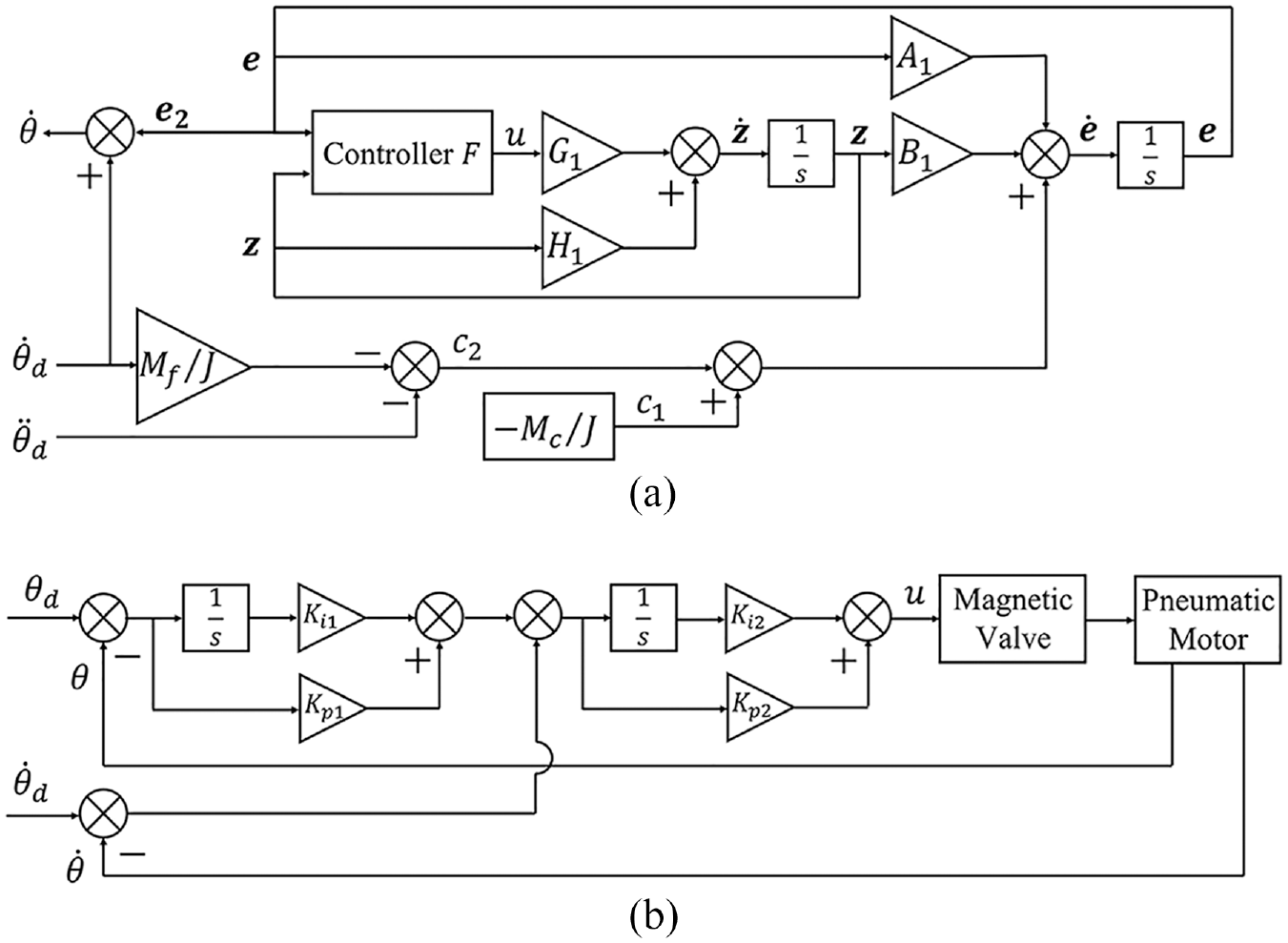
(a) Block diagram of the proposed model-based nonlinear controller and (b) block diagram of a conventional model-independent PID controller.
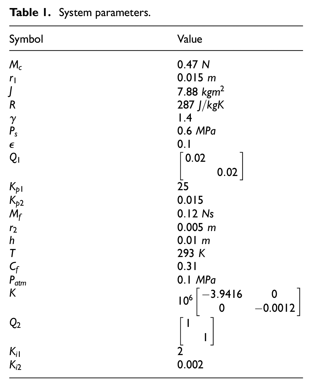
System parameters.
Control test results
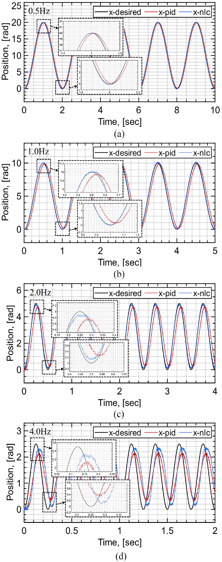
Figure 5 plots the position tracking results of the MRI-compatible pneumatic motor for sinusoidal velocity inputs with 100 rpm amplitude and frequencies ranging from 0.5 to 4 Hz. Both of the PID controller and the proposed nonlinear controller are capable of achieving high tracking accuracies with good transient response when the command is with relative low frequency. However, it should be noted that the actual angular position curves (represented by red and blue lines) deviate marginally from the desired position profile (represented by the black line) at the peak. This phenomenon can be attributed to the existence of Coulomb friction torque
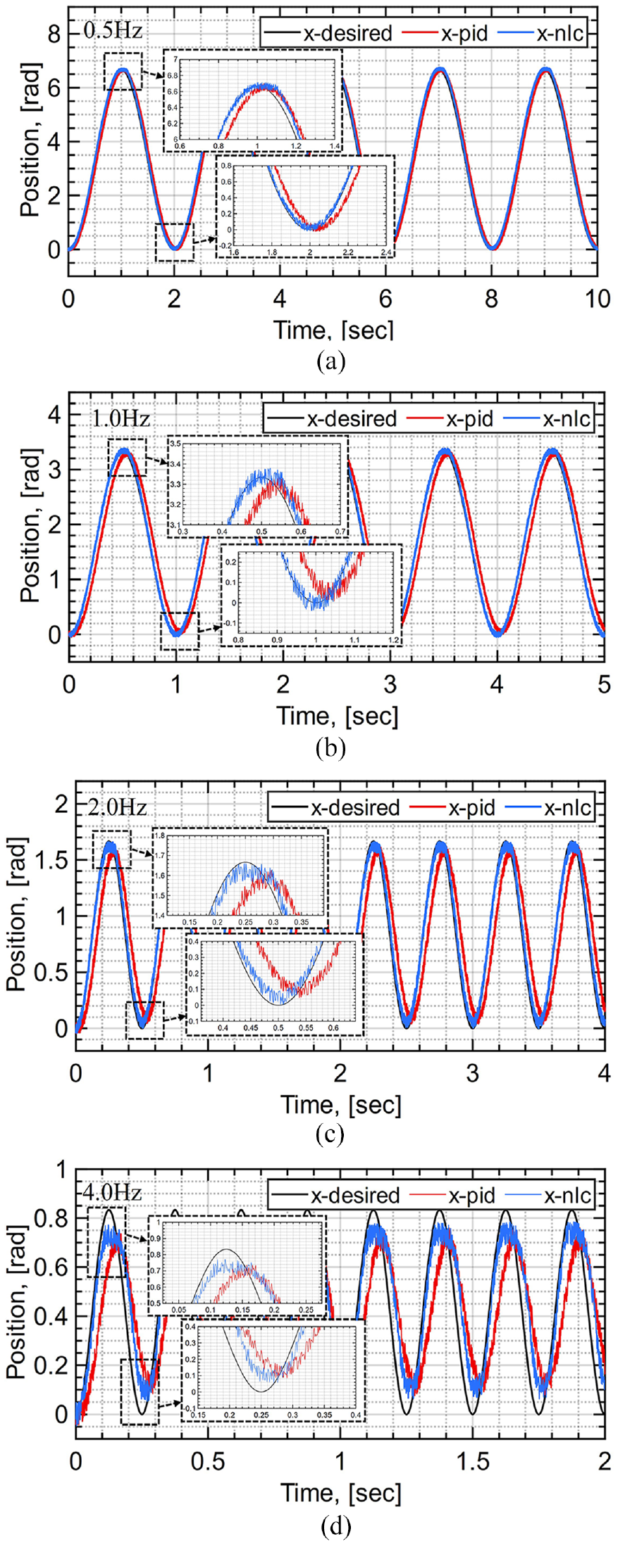
Position tracking results of two control methods for sinusoidal velocity inputs with 100 rpm amplitude. Frequencies: (a) 0.5 Hz, (b) 1.0 Hz, (c) 2.0 Hz, and (d) 4 Hz.
Corresponding velocity tracking results with 100 rpm amplitude are plotted in Figure 6. The bumps within the velocity tracking curve of the nonlinear controller around zero in Figure 6 result from the inherent control law mechanism which considers various frictions and bounded variables. This occurrence subsequently leads to the previously discussed position tracking results, which are more prominently visible in the 4 Hz case. It is worth mentioning that, with an increase in command frequency, the PID controlled motor exhibits significant amplitude attenuation and phase lag. Conversely, the nonlinear controller showcases exceptional transient tracking ability, albeit with slight deformation observed in the actual angular velocity profile in the 4 Hz case, owing to the aforementioned reason.
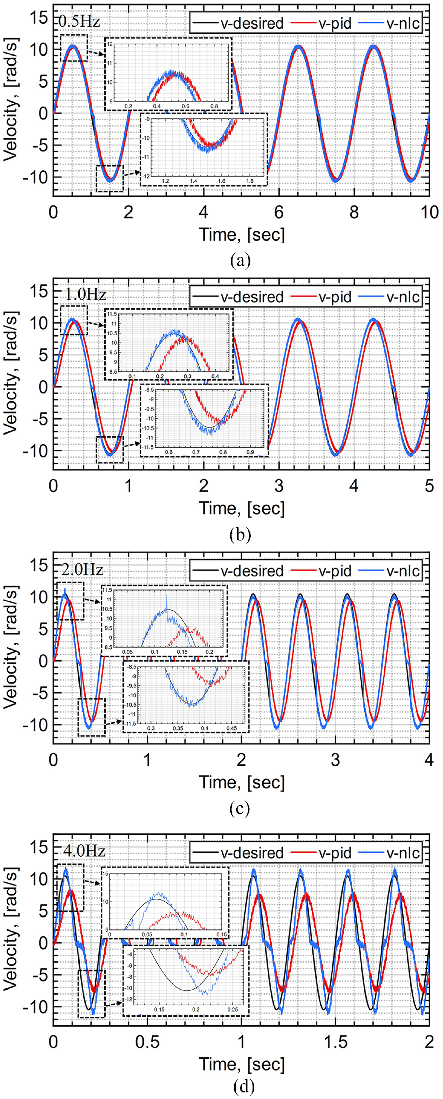
Velocity tracking results of two control methods for sinusoidal velocity inputs with 100 rpm amplitude. Frequencies: (a) 0.5 Hz, (b) 1.0 Hz, (c) 2.0 Hz, and (d) 4 Hz.
Further control tests have been performed to evaluate the control capabilities of the proposed nonlinear controller on the pneumatic motor for different amplitudes and frequencies. Figures 7 and 8 present the results obtained for sinusoidal velocity inputs with a 300 rpm amplitude and frequencies ranging from 0.5 to 4 Hz. The findings are consistent with those of the previous experiments, wherein the proposed nonlinear controller achieves faster and more precise tracking of the desired angular velocity profile compared to the PID controller. However, it should be noted that both controllers exhibit similar phase lag in position response at 4 Hz, albeit the nonlinear controller exhibits less amplitude attenuation, as illustrated in Figure 7(d). Notably, at even higher frequencies, none of the controllers exhibit tracking capability, possibly due to the mechanical limitations of the motor itself. In terms of velocity response, the motor controlled by the nonlinear controller showcases certain phase lag but negligible amplitude attenuation as the command frequency increases, while the PID controller fails at both aspects. Conclusively, the proposed nonlinear controller shows superiority and the reason behind is that the nonlinear controller considers more model information to promote the control accuracy.
Position tracking results of two control methods for sinusoidal velocity inputs with 300 rpm amplitude. Frequencies: (a) 0.5 Hz, (b) 1.0 Hz, (c) 2.0 Hz, and (d) 4 Hz.
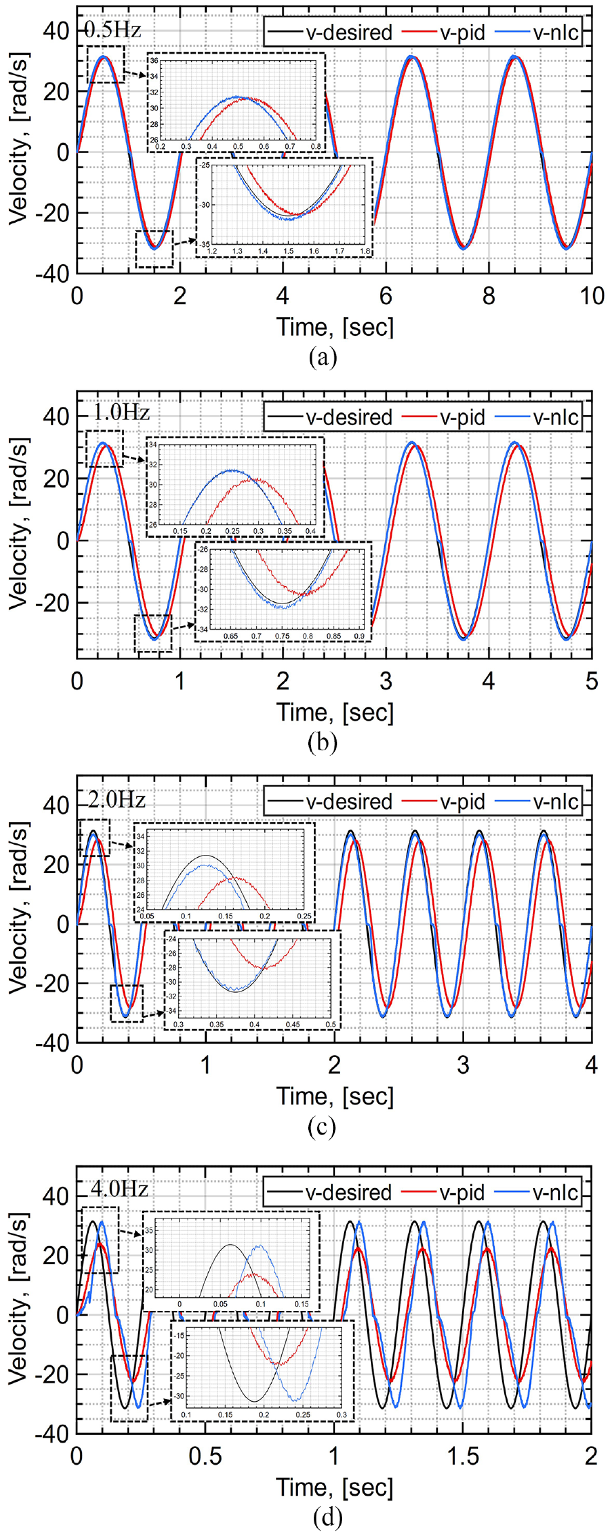
Velocity tracking results of two control methods for sinusoidal velocity inputs with 300 rpm amplitude. Frequencies: (a) 0.5 Hz, (b) 1.0 Hz, (c) 2.0 Hz, and (d) 4 Hz.
Figure 9 displays the bode plots of the position and velocity tracking results obtained for the pneumatic motor controlled by the proposed nonlinear controller and the PID controller, respectively. The blue solid line and dash line represent the nonlinear controller, whereas the red solid line and dash line correspond to the PID controller. The position tracking results suggest that the proposed nonlinear controller is capable of improving tracking accuracy with less amplitude attenuation and phase lag. As for the velocity tracking perspective, the nonlinear controller is able to closely follow the desired velocity profile with barely any amplitude attenuation. However, it is noteworthy that the phase delay increases with an increase in frequency and approaches a value similar to that of the PID controller at 4 Hz. Nonetheless, the findings indicate that the proposed nonlinear controller effectively enhances the operating accuracy of the pneumatic motor actuator under various working conditions.
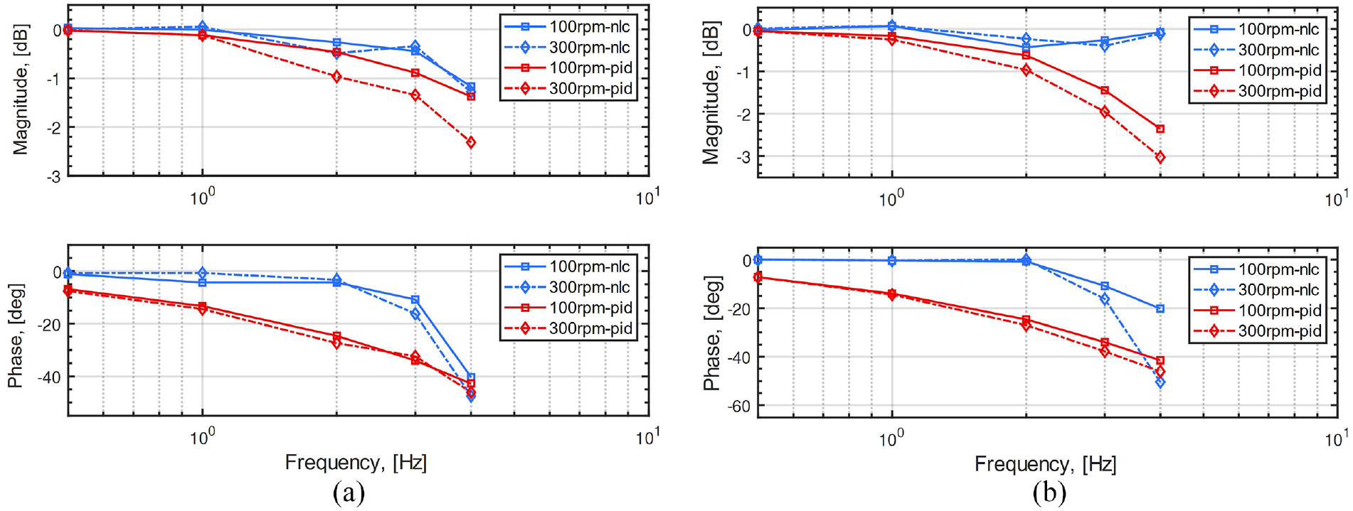
Bode plots of the pneumatic motor system controlled by the nonlinear controller and the conventional PID controller: (a) position response and (b) velocity response.
Discussion
Pneumatic actuators are the most widely researched and utilized for MRI-compatible surgical robots. Pneumatic motor stands itself out thanks to its fast manufacturability, compact size, medical sterility and most importantly bidirectional motion ability. Yet, model-independent PID controller is used for surgical robots built upon such actuators, resulting in low accuracy and operating speed. This paper proposed a novel model-based nonlinear controller for an MRI-compatible pneumatic motor to overcome these aforementioned issues, promoting the surgical operating accuracy and speed. The control performance was evaluated and analyzed through experiment tests upon a prototype, along with comparison with a conventional PID controller. Control performance superiorities with respect to amplitude attenuation and phase delay were directly observed, demonstrating the advantages of the proposed nonlinear controller. Although some may argue that better results could be achieved via carefully designing the PID parameters, no tedious parameter tunning is required for the model-based nonlinear controller.
Still, room exists for controller refinement. For the sake of safety concern, proportional magnetic solenoid valves and pressure sensors should be placed significantly away from the MRI-compatible robots, with long transmission air hoses connecting in between. Pressure attenuation and mass flowrate delay are therefore inevitable, inducing more nonlinearity into the system and limitation on observability, which are not considered in this work. Turkseven and Ueda proposed a pressure observer to promote the MRI-compatible robot control accuracy. 17 The author refined the observer and designed a new energy based Lyapunov candidate function considering the kinematic energy within the long air hoses and potential energy within the pneumatic actuators, which is then mathematically proved to be globally stable. 30 Therefore, future work could combine the proposed model-based nonlinear controller with the pressure observer to fully permit the usage of the MRI-compatible pneumatic motor and corresponding controller within MR environment.
Conclusion
The present study proposes a model-based nonlinear control method for the MRI-compatible pneumatic motor, which employs a turbine architecture to enable bidirectional torque/motion generation. The proposed controller utilizes more system information and necessitates only a few user-defined parameters to enhance system control performance. Experimental tests reveal the superiority of the proposed nonlinear controller over the traditional model-independent PID controller. The proposed controller can be customized by other researchers for different applications. The author envisions that this model-based nonlinear controller, in combination with the MRI-compatible pneumatic motor, will serve as a standard “servomotor” to act as revolute joints for MRI guided surgical robots, facilitating advanced velocity control instead of just position control.
Patents
The author has filed two patent applications for the MRI-compatible pneumatic motor designs with application No. 202210917259.7 on August 1st, 2022, and application No. 202211237897.0 on October 11th, 2022.
Footnotes
Appendix
Declaration of conflicting interests
The author declared no potential conflicts of interest with respect to the research, authorship, and/or publication of this article.
Funding
The author disclosed receipt of the following financial support for the research, authorship, and/or publication of this article: This work was supported by the Foundation for Shenzhen Science and Technology Program (Grant No. RCBS20221008093104018).