
Abstract
This article presents an innovative wall-climbing robot for detection on smooth wall surfaces, which consists of a vacuum adsorption system and adhesion belts, making the robot flexible and effectively steerable. Moreover, the detailed attachment mechanism is further analyzed for the climbing tasks. Safe operating conditions, kinematics, and dynamic model are derived, respectively, indicating that at least the adsorption force of 30 N and the motor torque of 2 N·m are required for stable climbing of the robot. Furthermore, the prototype of the wall-climbing robot is manufactured and the climbing abilities are tested on various wall surfaces showing that the maximum moving speed and corresponding load are 7.11 cm/s and 0.8 kg on the concrete exterior wall, 5.9 cm/s and 0.75 kg on the ceramic brick wall, 6.09 cm/s and 0.85 kg on the lime wall, and 5.9 cm/s and 1 kg on the acrylic surface, respectively, which demonstrates that the robot has high stability and adaptability.
Introduction
The wall-climbing robot can help human avoid engaging in the dangerous high-altitude work, which can not only increase the work efficiency and save the cost, but also improve the working environment of operators. As an important equipment to replace human working on steep walls and obtain real-time environmental information in three-dimensional (3-D) space, wall-climbing robots can improve working efficiency and ensure operation safety. They can be widely applied in the detection of chemical equipment and nuclear fuel tanks, cleaning of glass curtain walls, anti-terrorism investigation, and other fields. The traditional wall attachment methods for wall-climbing robots such as vacuum, magnet, and static electricity are only suitable for specific application scenarios. 1 –5 To meet the task requirements of accommodating various complex walls, a series of bionic wall-climbing robots have been developed by imitating the special attachment and movement capabilities of creatures including geckos, spiders, salamanders, and other insects. However, most of the existing biomimetic wall-climbing robots can only climb on a single type of wall surface and cannot realize the synergistic combination of multiple attachment methods, which fail to solve the stability and adaptability problems on different wall surfaces.
The vacuum suction method is mainly to discharge the air inside the suction cup by a high-speed fan or an external vacuum generator to form a partial vacuum, which can press the robot on the wall surface. Luk et al. have developed robots including three types (Robug II, 6 Robug III, 7 Robug IV 8 ), which are inspired by crab and spider for the maintenance and inspection of nuclear power plants. The negative pressure inside each suction cup is provided by an external vacuum generator. Due to the large size of the robot, the effective contact area between the suction cup and the wall surface is small, which leads to the unstable gait of the robot during the performance testing. To make the robot have greater adaptability and over-obstacle capability, Minor et al. developed a two-foot wall-climbing robot by simplifying the structure and adopting underactuated mode, named RAMR, which effectively reduced the whole weight. 9 Nevertheless, the robot has less stability during moving because of its high center of gravity position. Zhou and Li designed a noncontact negative pressure wall-climbing robot using the sealing edge, which can effectively avoid too close contact between the suction cup and the wall surface. 10 However, due to the heavy weight of the robot, it is impossible for the robot to climb on ceiling walls, and the sealing device is soft such that it can be worn easily.
In nature, geckos and flies can crawl flexibly on a variety of complex walls and even move quickly on smooth ceiling walls without falling. The reason is that there are three nerves in the foot that control the claw pad valgus, adduction, and foot rotation and can freely switch between the three modes. Menon et al. have developed a wall-climbing robot named Tankbot in 2004. 11 –14 The robot can climb on a smooth wall surface of 110° by sticking adhesive materials on the track. Due to the influence of the robot’s own structural design, when the turning radius is relatively small, the adhesive materials on both sides of the robot will slip, which enable it only climb in a straight direction. In addition, Sitti et al. have also developed a 16-foot wall-climbing robot based on the linkage driving mechanism inspired by the gecko’s movement gait. 15,16 The robot is composed of 16 adhesive foot pads, which can realize the alternating movement of the motion module on the wall by sequentially controlling the left and right two motors. After experimental testing, the robot can also climb on the surface of metal, wood, and paint with a roughness of tens of microns at a maximum speed of 4 cm/s, although some bionic adhesion wall-climbing robots have achieved climbing on vertical walls and ceiling walls. However, the scope of application is very limited, only suitable for some wall surfaces such as glass and painting indoor smooth walls with dust-free or a small amount of dust. In addition, the type of robot has a very small load capacity and low material reusability, whose manufacturing process of the adhesive material is also very complicated. Besides, the base of the track or the adhesive pads made of adhesive material is also relatively soft and difficult to support the weight of the entire robot.
Obviously, it can be seen that the single moving mode is difficult to make the robot stable for a variety of wall surfaces. For the detection requirement with fast locomotion on smooth surfaces and comprehensive consideration of the excellent performances of adhesive materials and vacuum adsorption system, a novel tracked wall-climbing robot with adhesive belts and an adsorption device is proposed.
This article is organized as follows. In the second section, the mechanism of the wall-climbing robot is proposed. In the third section, the safe operating conditions are analyzed. In the fourth section, the kinematic and dynamic model are described. In the fifth section, experiments are carried out to verify the climbing performance of the robot. The conclusion and future work are presented in the last section.
Mechanical design
Abalone usually uses its wide fleshy foot to firmly adsorb the rock to prevent itself from being washed away by the waves and attacked by natural enemies. Adult wild abalone with a shell length of 15 cm has an adsorption capacity over 200 kg. 17 The fundamental reason is the vacuum adsorption force formed by skirt edge under the fleshy foot and the rock wall, as shown in the top of Figure 1(a). In view of the excellent adsorption ability of abalone, a suction cup and flexible skirt edge are manufactured, as shown in Figure 1(b). Beyond that, it was found that the adhesive pads of flies are covered with tens of thousands of micro–nano and nano-bristles, as shown in Figure 1(a), which generate van der Waals force with wall surface. In the study of adhesive materials, it is found that the materials that can be currently used for bionic adhesive feet include polyurethane, silicone rubber, polyimide, and so on. Among the above materials, polyurethane contains more urethane in the macromolecular structure. 18,19 So, it has higher surface energy and can change the contact shape with the size of the wall particles. Therefore, the polyurethane could be chosen as the adhesive material. In view of the adhesive characteristics of the polyurethane, the adhesive belts with many surface array features can be produced by the casting method, as shown in the below of Figure 1(b)

Structure of the wall-climbing robot. (a) The flexible skirt edge of abalone’s suction cup (top) and fly’s adhesive pad (below), (b) the vortex fan (top), bionic flexible skirt edge (middle) and adhesive belt (below), (c) the principle prototype and remote control system, 1—remote controller, 2—control panel, 3—left driving motor, 4—left adhesive belt, 5—vortex fan, 6—suction cup, 7—right driving motor, 8—right adhesive belt.
The robot consists of four parts, which are the main motion system, the adsorption system, the adhesion system, and the control system, as shown in Figure 1(c). The main motion system includes two brushless DC motors installed on the front of the frame, which can drive the adhesive belts to realize the ascending, descending, and turning of the robot. The adsorption system contains a vortex fan, suction cup, and flexible skirt edge, which can provide the robot with the adsorption force to ensure it be attached to the ceiling or vertical walls. Adhesion system provides adhesive force to the robot by means of the contact with wall surfaces, which is composed of two adhesive belts. The control system is comprised of a control panel and a remote controller to adjust the rotational speed of the vortex fan and the driving motors in real time. The robot has the 3-D size 200 × .195 × mm2. In the process of the robot’s climbing the wall, the robot must be relatively light in order to adapt to the requirements of long-term operation. Therefore, we have designed lightweight parts for the robot. The driving and driven wheels are made of nylon by 3-D printing technology. Other components such as the frame, the suction cup housing, the fan holder, and so on need to bear larger loads, so the high-strength aluminum–magnesium alloys would be used as processing materials.
Adsorption system
The structure of adsorption system is shown in Figure 2, including a vortex fan, a fan frame, a suction cup, and a flexible skirt edge. The diameter of the vortex fan is 80 mm, and eight curved blades are distributed inside. The operating principle is similar to that of the centrifugal pump. 20,21 The inner air is discharged to form pressure difference through the rotation of the impeller, which ensures that the robot can be attached to the wall surface. The only difference lies in the structure design of the flexible skirt edge composed of wear-resistant fabric and elastic adaptive material, which can effectively reduce the external air into the suction cup. When the flexible skirt edge contacts the wall, it will change its shape according to the surface characteristics of the wall to stop outside air from entering the suction cup.

The virtual prototype model of adsorption system.
Due to lower flow rate of air leakage into the suction cup, the state of the air can be considered as laminar flow. Therefore, Navier–Stokes equations can be used.
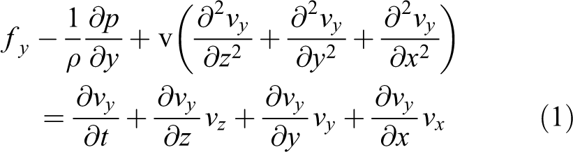
where fy is the mass force in the y direction, ρ is the density of air, and p is the pressure in the gap.
Assuming that the gas leakage rate is uniform and not compressible, then we can obtain
Substituting equation (2) into equation (1)

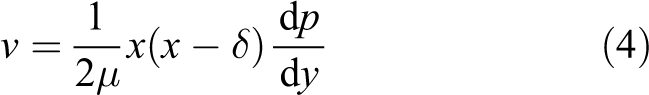
where v is the velocity of inlet and μ is the dynamic viscosity.
Integrating equation (3) twice and according to the boundary conditions: x = 0, v = 0; x = δ, v = 0. The equation of the flow velocity can be written as
Then, the total flow into the suction cup is

where l 1 and l 2 are the length and width of flexible skirt edge, respectively; p 0 is the standard atmospheric pressure; and p 1 is the internal pressure of suction cup.
Taking a = 10 mm,

Fluid model of the suction cup.

The relationship between air leakage and the gap on the conditions of different pressure differences. The x-axis represents the gap between the skirt edge and the wall, and the y-axis represents the amount of air leakage into the suction cup.
The force model of the skirt edge is shown in Figure 5, which gradually increases from the outside to the inside of the suction cup in the y direction. Then, the sum of the force at the joint of the suction cup skirt and the wall is


The force model of the skirt edge.
where p 0 is the outside atmospheric pressure (Pa), p 1 is the air pressure in the suction cup (Pa), l 1 is the length of the skirt edge (m), and l 2 is the width of the skirt edge (m). It can be seen from equation (6) that the skirt produces an adsorption force perpendicular to the wall surface, which press the suction cup tightly to reduce the gap between the skirt edge and the wall surface, so the power consumption required by the fan will also be greatly reduced.
The power required by the fan is
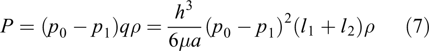
According to equation (7), the energy consumed by the fan is proportional to the cube of the gap, the square of the pressure difference, the air density, and the size of the skirt edge and inversely proportional to the width of the skirt and air viscosity.
The relationship of the power energy versus the gap and pressure difference is shown in Figure 6. When the gap is less than 0.6 mm, the power energy consumed by the fan will change slightly. When the gap is larger than 0.6 mm, the change rule of the power is similar to the air leakage. Setting the maximum pressure difference between the inside and the outside of the suction cup to 1000 Pa and the gap to 0.6 mm, then we can know that the power energy is 40 W. The rotational speed and the voltage are selected to be 20,000 r/min and 18 V, respectively, and the rated torque of the motor can be introduced to 0.02 N m.

The relationship of the power energy versus the gap and the pressure difference.
The adsorption force can be described as

where S is the contacting area.
Substituting equations (5) and (7) into equation (8), the adsorption force can be transformed into

The flexible skirt edge is designed to realize the sealing performance to stabilize the adsorption force and reduce the resistance during the process of climbing wall. Therefore, the selection of the sealing material and structure design greatly affect the adsorption performance of the suction cup. At present, there are many materials for sealing device and mostly polyethylene. Although the sealing effect has been improved, the abrasion of bottom skirt edge is more serious. 22 –24
To obtain the optimal sealing state, it is necessary to establish a force model containing the structural parameters and pressure difference for the sealing device, as shown in Figure 7. According to the material bending deformation theory, we can obtain


Sealing mechanical model of the flexible skirt edge.
where d is the height of the flexible skirt edge,
Adhesive belts
The manufacturing steps of the adhesive belt is as follows: Firstly, the silicon wafer was washed with alcohol, acetone, hydrogen peroxide, and concentrated sulfuric acid in order. After soaking for 8 h, the silicon wafer put into a mixed solution of deionized water, silver nitrate, and hydrofluoric acid and soaked it for 2 h. Next, the silicon wafer was put into the mixed liquid of deionized water, hydrogen peroxide, and hydrofluoric acid again to etch the silicon wafer for 480 s to obtain the array features on the surface. After soaking the silicon wafer in concentrated nitric acid for 60 s, we can obtain the template of adhesive material with micro–nano array features. 25 Secondly, the polyurethane liquid is poured onto the surface of the silicon wafer to get an adhesive material. Finally, the adhesive material is affixed to the surface of the rubber belt; then, the required adhesive belt is manufactured after heating for 1 h in the insulation.
Adhesion performance testing equipment adopts HP-10 series hand-cranked tension and pressure dynamometer made by Aidebao Co., Ltd (China), as shown in Figure 8(a), whose maximum range load is 10 N. The equipment consists of a frame, a digital display scale, a push-pull gauge, an upper clamp and a lower clamp, and a hand-cranking device. When testing the tension and pressure of the adhesive material, the adhesive material is fixed on the glass surface, then the handwheel is used to move the supporting rod up and down to realize the adhesive performance testing in different situations. Finally, the testing data are converted into electrical signals and transmitted to the computer, which can be recorded in real time through the software. The experiments of adhesive material mainly include the following parts: (1) the elastic modulus, (2) the change of adhesion force with pressing force, (3) changing trends of tangential and normal forces in different tensile directions, and (4) surface adhesion energy. The different testing methods of the adhesion material are shown in Figure 8(b) and (c).

The performance testing of the adhesive material. (a) Pull and pressure testing instrument, (b) the method of vertical preloading and vertical pulling, and (c) the method of vertical preloading and pulling in different angle.
In Kendall’s adhesive peeling theory, it can be known that the peeling force is related to the material elastic modulus which can be obtained according to Hooke’s law.

where

The relationship between pressing force and thickness change of adhesive material.

The relationship between elastic modulus and thickness change of adhesive material.
The variation of adhesive force relative to pressing force is shown in Figure 11. The negative value represents the pressing force and the positive value represents the adhesive force in the figure. When the pressing force is less than 0.5 N, the maximum value of the adhesion force gradually increases as the pressing force increases. When the pressing force is greater than 0.5 N, even if the pressing force continues to increase, the changing range of adhesive is relatively small, remaining at about 4 N. Therefore, we can speculate that the pressure per unit area is 0.013 MPa.

The variation of the adhesive force relative to pressing force.
Figure 12 shows the relationship between the maximum peeling force and the peeling angle when the pressing force is 0.5 N. With the increase of the peeling angle, the peeling force gradually decreases linearly. Since the peeling angle of the adhesive belt and the wall is 60–70°, the required peeling force is about 6 N.According to Kendall’s peeling theory, the surface energy can be obtained as

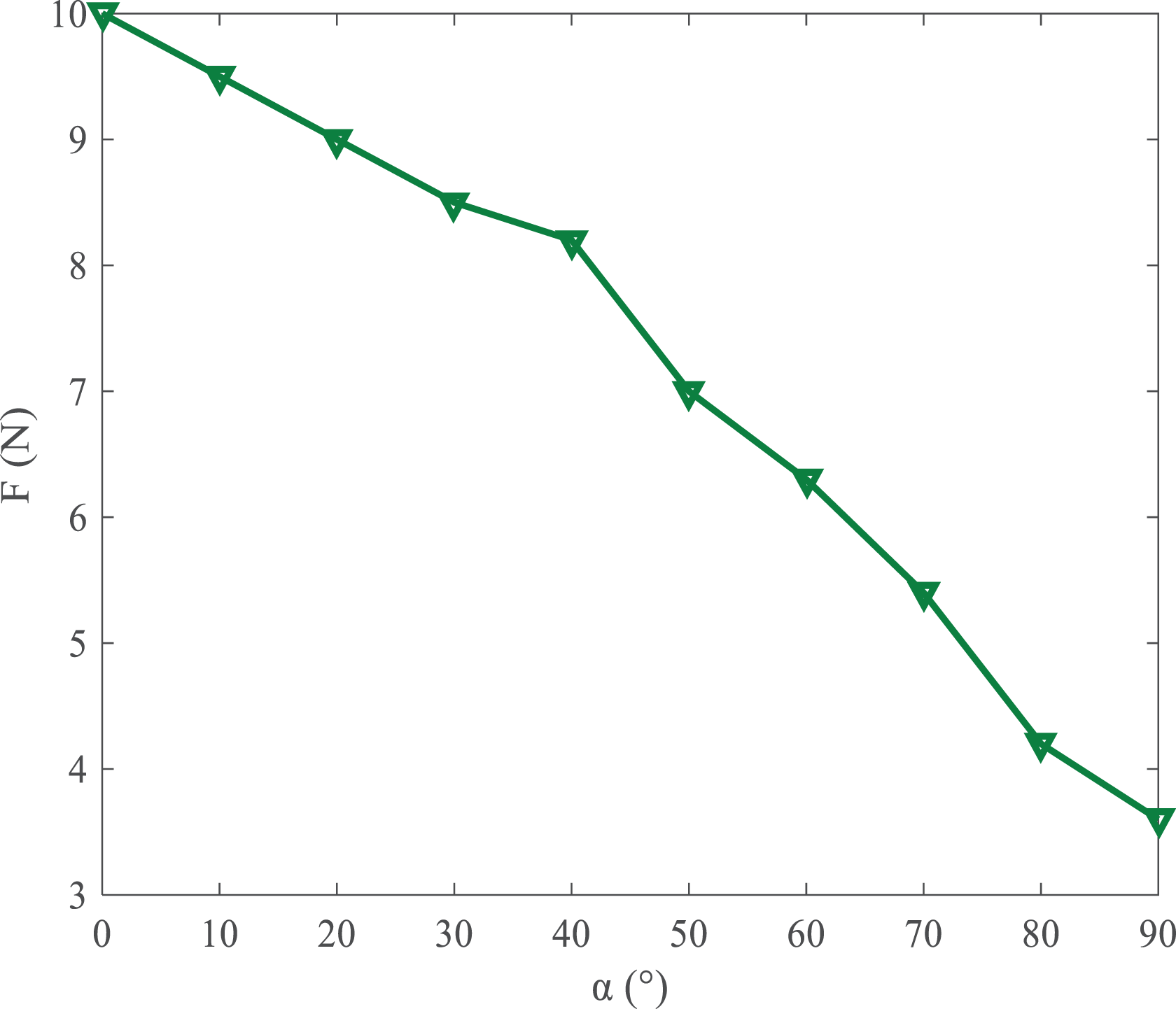
The relationship between the maximum peeling force and the peeling angle.
Substituting the values of the elastic modulus, the peeling angle, and the peeling force, we can derive the range of surface adhesion energy to be 437.25–472.25 J/m2.
The adhesive belt is not only affected by the peeling force but also by the preload. The peeling process of the adhesive belt from the smooth wall is shown in Figure 13, where F is the peeling force, θ is the peeling angle, r is the radius of the pulley, and d is the thickness of the adhesive belt.According to the triangular geometric relationship in Figure 13, the original and stretching length of the AB section is as follows, respectively:

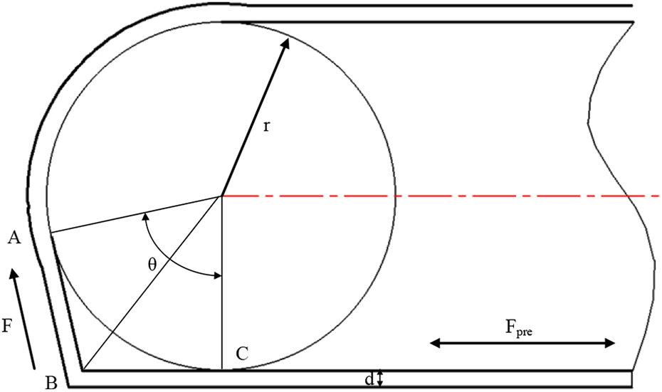
The peeling process of the adhesive belt from the smooth surface.
Based on the linear elastic theory, the peeling force can be described as

where b is the width of the adhesive belt and
According to equations (13) and (14), the peeling force can be transformed into

During the peeling process of the adhesive belt from point B to point C, the energy changes are as follows: The surface energy generated by the new surface peeling is The potential energy term due to the movement of force is The elastic potential energy with the elastic deformation of the adhesive belt is

The energy is added during the peeling process, then we can obtain

By simplifying equation (16), the preload can be deduced as follows:

Substituting the known elastic modulus, width, thickness, and surface adhesion energy into equations (15) and (17), the relationship of peeling force and preload force versus peeling angle can be seen in Figure 14. As the peeling angle increases, the peeling force and preload force also gradually become large.

The relationship between the peeling force and preload force versus the peeling angle.
In addition, it can also be found that the maximum preload force is 8 N within peel angles from 0° to 90°, which is proportional to the peeling force. While the value of the preload force is relatively small, the belt is always in a slack state, in which a slight force can peel the adhesive belt from wall surfaces. The peeling angle is chosen to be 60°, so the component of the peeling force in the normal direction is 13 N, which is more than two times larger than the experimental values.
The main reason is that the effect of the initial preload force on the adhesion force has not been considered during the performance testing for the adhesive material.
Analysis of safe attachment conditions
The greater the adsorption force of the robot’s suction cup is, the higher the motion stability on various walls gets; however, the motion flexibility and power consumption will increase. To quantitatively investigate the robot’s safe attachment conditions, the stability of robot needs to be analyzed to determine the relationship of the adsorption force versus the gravity component and the friction coefficient. On smooth walls, the main forms of instability are integral slipping, flipping around the contact points between the rear belts and walls, and flipping around the left (or right) adhesive belt.
Integral slipping
The reason why the robot occurs integral slipping is the friction between the belts, and the center skirt relative to the wall cannot overcome the gravity component along the wall. The friction is determined by the support force of the wall, which depends on the adsorption force. The slipping model is shown in Figure 15, in which f is the friction force of adhesive belts and flexible skirt edge exerted by the wall,


The integral slipping model.
where

Flipping around the contact points between the rear adhesive belt and the wall
The flipping around the contact points between the rear belt and the wall generally occurs near vertical walls, as shown in Figure 16. The main reason is that as the inclination of the wall increases, the component of gravity in the vertical direction gradually increases. To prevent the robot from flipping backward, then


The flipping model around the contact points between the rear belt and the wall.
where

Flipping around the left (or right) adhesive belt
The flipping model around the left (or right) adhesive belt is shown in Figure 17.
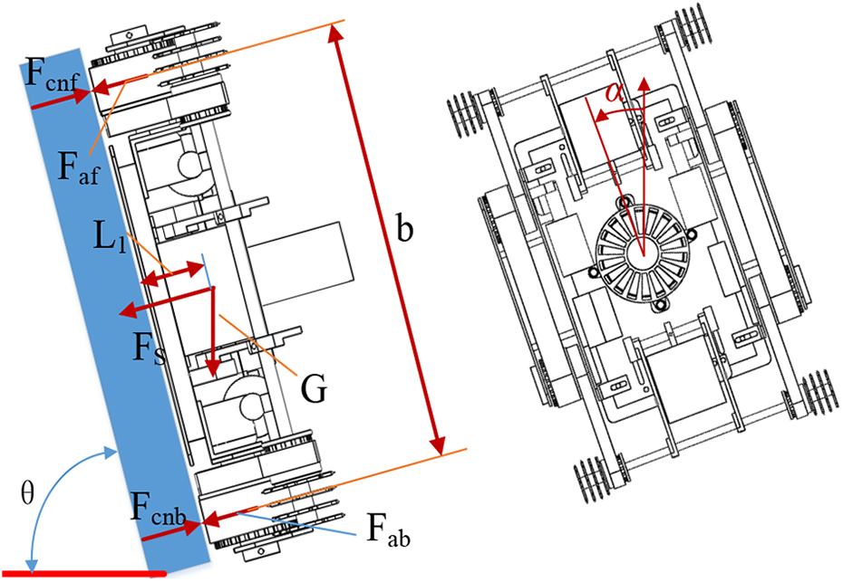
The flipping model around the right adhesive belt.
The sufficient and necessary condition for the robot’s no overturning is that the upper normal support force is not smaller than 0, then we can obtain

The expression of the adsorption force can be derived as

In conclusion, the safe operation conditions of the robot on smooth walls are as follows:

To directly express the magnitude of the adsorption force, the simulation of the adsorption force is performed, as shown in Figure 18. The known parameters are G = 19.6 N,
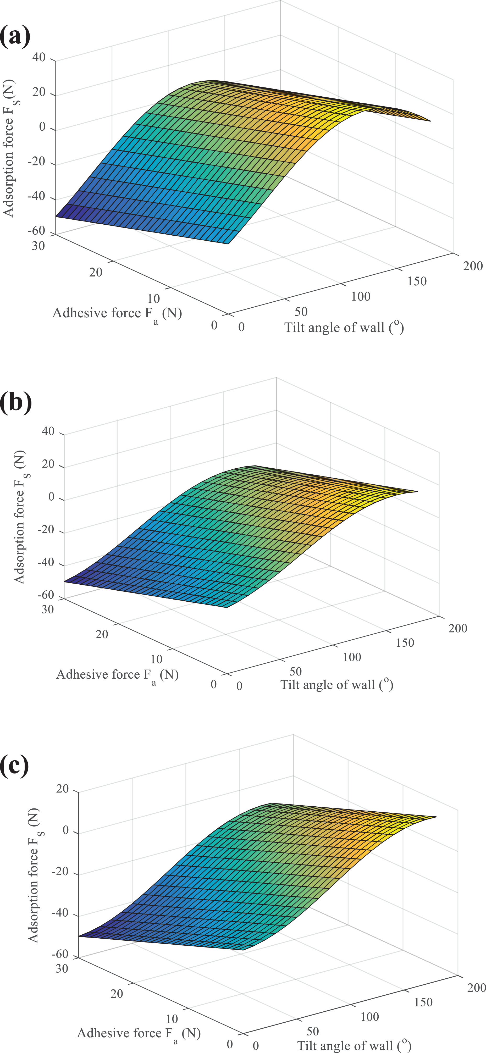
Variation of adsorption force relative to adhesive force and tilt angle of the wall. (a) Adsorption simulation during integral slipping, (b) adsorption simulation during flipping around the contact points between the rear belts and walls, and (c) adsorption simulation during flipping around the left adhesive belt.
Kinematics and dynamic analysis
Kinematics analysis
The kinematics analysis of a robot on a smooth wall can be simplified to the research of a similar movement mechanism of the tank track, as shown in Figure 19, in which O is the instantaneous center of the robot; O
1 and Or
are the rotational center of the left and right adhesive belts, respectively; b is the center distance of the left and right adhesive belts; L is the effective contact length of adhesive belts; and γ is the slipping angle, φ is the navigation angle, and d is the center offset. In the coordinate system x
1
o
1
y
1, the kinematics equation of the robot is as follows:


The kinematic model of the robot.
In the global coordinate system, it can be converted to

According to the triangle geometric relationship in Figure 19, we can get

where
Equation (27) can be changed to

Substituting equation (28) into equation (26), the final kinematics expression of the robot can be obtained

Since the wall-climbing robot is only applicable to the vertical climbing movement, there is no lateral movement. Therefore, the values of the navigation angle φ and the slip angle γ are 0. According to equation (29), the robot has only motion speed in y-direction, which is
Dynamic analysis
Before establishing the dynamic model of robot on smooth walls, the friction and frictional resistance moments of the adhesive belt need to be calculated first. Taking a single adhesive belt as an example, the mechanical model is shown in Figure 20.

The mechanical model of a single adhesive belt.
The friction force of the adhesive belt per unit area is
Then, the friction force component

The friction force component

The friction moment


The solutions of equations (31)–(33) are very tedious. To simplify the calculation, it is assumed that the adhesive belt on both sides of the rotational center is uniformly stressed. During the movement, the adhesive belt is only affected by the friction force in x-direction and the friction moment.


According to the Newton–Euler equation, in the coordinate system x 1 o 1 y 1, the dynamics of the robot is expressed as follows

where m is the mass of the robot, G is the gravity, I is the moment of inertia of the robot around point E,

Since the robot is only suitable for up and down movement in vertical walls, the navigation angle φ and the instantaneous center offset d are 0. Therefore, it can be seen that the driving torque is only related to the robot’s own gravity, peeling force, peeling angle, adsorption force, and friction coefficient.
Experiments
Dynamics simulation and validation
To verify the dynamic model of the robot on a smooth wall surface, a vertical lime wall surface is used as the test platform. It is assumed that the robot climbs upward at a constant moving speed. The torque sensor made by Co. Ltd (model: DYJN-104, the range: 3 N·m, and the accuracy: 1%). Setting the safety factor to 2, the simulation results are shown in Figure 21. The theoretical value of the motor driving torque is 1.43 N m, and the deviation of the experimental value is basically maintained at 0.3 N·m during the uniform motion. However, the experimental values reached nearly 1.9 N·m at 1 s, which is caused by some close contact between the adhesive belt and the wall increasing the peeling difficulty. Selecting the voltage of the motor to 18 V and based on experiment results, the rated torque of the motor can be selected as 2 N·m. Assuming that the radius of the pulley to 1.8 cm and the maximum speed of the robot to 10 cm/s, therefore, the rated speed of the motor can be derived as 55 r/min.

The comparison of theoretical and experimental motor torque.
Wall-climbing performance
Based on the above theoretical analysis, the principle prototype of the wall-climbing robot is manufactured using 3-D printing and precision machining technology. The frame is made of high-strength aluminum–magnesium alloy, and the tracked wheels are printed with PA2200 nylon material. The robot weighs 2 kg and is powered by a lithium battery whose capacity and voltage are 3300 mAh and 18 V, respectively. The wireless remote control module can realize the robot’s moving forward, backward, and turning at different speeds. Also, it can change the rotational speed of the fan to adjust the negative pressure in the suction cup. A miniature camera is installed on the front of the robot, which can wirelessly communicate with mobile phones and computers to record the characteristics of the wall in real time, which is convenient for the staff to accurately detect the wall surface.
To verify the wall-climbing performance of the robot on various wall surfaces, the concrete exterior wall, the ceramic brick wall with a gap (5 mm deep and 8 mm wide), the lime wall, and the acrylic surface are used as testing platforms, as shown in Figure 22. The moving speed and load capacity are important indicators for evaluating the climbing ability, and experiment results on the vertical wall are shown in Table 1. Through the four groups of experiment on the above walls, we can know that the maximum moving speed and corresponding load are 7.11 cm/s and 0.8 kg on the concrete exterior wall, 5.9 cm/s and 0.75 kg on the ceramic brick wall, 6.09 cm/s and 0.85 kg on the lime wall, and 5.9 cm/s and 1 kg on the acrylic wall, respectively. According to the comprehensive analysis of the above experimental results, the robot has the smallest load on the ceramic wall surface due to the air outside entering in the gap among ceramic bricks, which causes the decrease of the vacuum adsorption force. The moving speeds of the robot on ceramic brick, lime, and acrylic wall are basically similar, because the characteristics of the above three walls are the same. On the concrete exterior wall, the robot does not need to overcome more peeling forces between adhesive belts and the wall, so it has a relatively fast-moving speed.

Wall-climbing performance testing. (a) On the concrete exterior wall, (b) on the ceramic brick wall with a gap, (c) on the lime wall, and (d) on the acrylic wall.
The testing of moving speed and load capacity for the robot on the four vertical walls.

Conclusion and future work
In this article, a novel multi-mode wall-climbing robot with the vacuum adsorption system and adhesive belts has been proposed for some smooth wall surfaces. By analyzing the safe operating conditions of the robot, it is shown that the minimum adsorption force is 30 N. Moreover, kinematic and dynamic models are set up to analyze the motion characteristics of the robot and the motor torque, respectively, and also provide a theoretical basis for the optimization of the control strategy. Furthermore, the prototype of the wall-climbing robot has been manufactured, whose climbing abilities have been tested on various wall surfaces, demonstrating that the maximum moving speed and corresponding load are 7.11 cm/s and 0.8 kg on the concrete exterior wall, 5.9 cm/s and 0.75 kg on the ceramic brick wall, 6.09 cm/s and 0.85 kg on the lime wall, and 5.9 cm/s and 1 kg on the acrylic surface, respectively, which show the robot has high stability and adaptability. In the future, we need to further investigate the attachment mechanisms adapting to multiple walls as far as possible and develop novel composite materials of the skirt edge for suction cup and adhesive belts.
Footnotes
Declaration of conflicting interests
The author(s) declared no potential conflicts of interest with respect to the research, authorship, and/or publication of this article.
Funding
The author(s) disclosed receipt of the following financial support for the research, authorship, and/or publication of this article: This work was supported by Science and Technology Major Project of Anhui Province [Grant No. 17030901034], Jiangsu Key Research and Development Plan [Grant No. BE2017067], and Project of National Natural Science Foundation of China [Grant Nos 61703390, 51705499].