
Abstract
As a new type of underwater observation platform, underwater glider is widely used in marine explorations and military surveys, and most gliders are powered by their own batteries whose capacities are limited. It is therefore necessary to analyze the energy consumption of underwater glider. In this article, the variation law of seawater density changing with depth is considered; based on the theory of rigid body dynamics, the motion model of blended-wing-body underwater glider is established; the energy consumption model of each component module is accounted by analyzing the energy consumption composition in the working process of blended-wing-body underwater glider; and the energy consumption under different navigation depths, different glide ratios, and different buoyancy adjustments regulation is simulated. The results demonstrate that as the glide depth is increased, the total energy consumption increases in a single cycle and decreases per gliding distance, leading to a smaller energy consumption ratio for the attitude adjustment module; on the other hand, as the buoyancy adjustment is increased, more energy is consumed in a single cycle and less energy is consumed per gliding distanced, resulting in a larger energy consumption ratio for the attitude adjustment module. As the glide ratio increases, the total energy consumption in a single cycle first increases and then decreases, while the energy consumption of per gliding distance and the energy consumption ratio of the attitude adjustment module are decreased.
Introduction
Underwater glider is a new type of ocean exploration platform which combines the technology of float and underwater robot, whose basic principle is to realize the gliding motion of floating up and diving by adjusting the size of gravity or buoyancy and the position of centroid. Underwater glider can carry out a large-scale and long-term monitoring task of marine environmental parameters in the target sea area by carrying a variety of detection sensors with different functions. It has the advantages of low energy consumption, long endurance, low maintenance cost, and high concealment. Since the concept of underwater glider was first put forward by American oceanographer Stommel in 1989, 1,2 many countries in the world began to study the technology of underwater glider. 3,4 At present, the most advanced underwater gliders mainly include Slocum Electric Glider produced by Webb Company, Seaglider developed by Washington University, Spray Glider developed by Scripps Institute of Oceanography, 5 Sea-Wing Glider developed by China Shenyang Institute of Automation, and the new blended-wing-body layout underwater glider Xray and Zray developed by US Navy Laboratory. 6 They have been applied in some marine environment observation missions. 7,8
At present, the energy for underwater glider to carry out its mission is mainly supplied by its own battery. Due to the limited capacity of the battery and the inconvenience of recharging or replacing the battery, energy consumption is one of the decisive factors for the endurance and range of underwater glider. The low-power technology has become one of the current research trends of underwater glider. Furthermore, in the analysis of energy consumption of underwater glider, the effect of seawater density changing on energy consumption cannot be ignored. Woithe et al. reduced the energy consumption of the detection system by studying the sensor adaptive sampling strategy of underwater glider, then developed the energy consumption tester for the Slocum glider, and analyzed the energy consumption of the main unit of the glider, finally established the task energy consumption simulation model to guide the mission planning. 9,10 In the work of Chen and Yu, 11 the Sea-Wing underwater glider range model based on energy consumption was established, and the navigation parameters and sensor control strategy of the glider are optimized. Zhu et al. 12 carried out the research of underwater glider path planning aiming at the lowest energy consumption. Sun established the energy consumption model of the wing-body-blended underwater glider and carried out the shape optimization design with the maximum range optimization objective. 13
In order to analyze the energy consumption of underwater glider, this article takes the self-designed underwater glider with blended-wing-body layout as an example, considering the law of seawater density changing with depth. The motion model of the blended-wing-body underwater glider is established based on momentum and momentum moment theory. Furthermore, the energy consumption components of the blended-wing-body underwater glider are analyzed, and the energy consumption models of each component module are established respectively. Then the dynamic model and the energy consumption model are used to simulate the energy consumption of the blended-wing-body underwater glider. Finally, the optimization suggestions for low-energy consumption gliding are given. This article provides a reference for the performance analysis of the blended-wing-body glider.
Energy consumption modeling
In order to establish the energy consumption model of blended-wing-body underwater glider, there are some assumptions as following: The underwater glider only glides in the longitudinal section, and it is completely wet. The influence of complex ocean environment such as current and wave is ignored. The glider has two symmetrical planes, and the process of diving and floating up is symmetrical.
Internal layout and work process
In this article, the self-designed underwater glider with blended-wing-body layout is taken as an example. Its internal layout is shown in Figure 1. The buoyancy adjustment module consists of two sets of oil storage tanks and outer oil pockets, and the pitch adjustment module consists of a movable slider. The motion process in the longitudinal profile is shown in Figure 2. The single cycle motion process mainly includes the diving stage, the floating up stage, and the communication and data transmission stage. During the diving and the floating up stage, the ocean information can be collected by the detection sensors. After receiving the diving instruction, the slider moves forward, which causes the glider centroid to move forward, and the oil in the pocket flows to the storage tank through the solenoid valve, thereby causing the buoyancy to decrease, then the glider starts to dive. After reaching the preset depth, the slider moves backward, which causes the glider centroid to move backward, and the oil in the storage tank is pumped into the oil pocket, thereby causing the buoyancy to increase and the glider starts to float up. When reaching the sea surface, the glider enters the data transmission stage which includes positioning by GPS and using Iridium or radio to communicate with the control station for information exchange. The glider begins entering the next gliding cycle after finishing data transmission stage.

The internal layout of blended-wing-body underwater glider.

The motion process in the longitudinal profile.
Motion model
Before establishing the motion model, two coordinate systems are defined: the ground coordinate system

The coordinate systems of the underwater glider.
Kinematic equations
According to the conversion relationship between the ground coordinate system and the body coordinate system, the kinematic equations of the glider can be described as follows 14,15


where
Dynamic equations
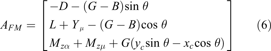
Based on the theorem of momentum and momentum moment of rigid body dynamics, the dynamic equations of the underwater glider can be expressed as follows

In the above equation,


where m is the mass of the glider;


where ρ is the density of seawater,
Adjustment process
The state parameters of the blended-wing-body underwater glider in the process of attitude adjustment change according to the following equations 16


where
Energy consumption model
According to the composition of the glider, the energy consumption of the underwater glider studied in the present study is mainly generated by five modules, namely, buoyancy adjustment module, pitch adjustment module, communication module, detection module, and navigation and control module. In the following, the energy consumption model of each module in the glide cycle will be established. 17,18
Buoyancy adjustment module
The buoyancy adjustment module is activated twice in a glide cycle: decrease of buoyancy at the beginning of diving and increase of buoyancy when starting to float up.
At the beginning of the diving stage, the solenoid valve between the outer oil pocket and the oil storage tank is opened, and the hydraulic oil in the outer oil pocket flows to the oil storage tank under the effect of atmospheric pressure. Since the glider begins to dive near the sea surface, the power Pv
and flow Qv
of the solenoid valve are considered as constant. If the buoyancy adjustment of the glider is

When the glider reaches the preset depth and turns to the floating up stage, the hydraulic pump between the outer oil pocket and the oil storage tank is turned on, and the hydraulic oil is pumped from the oil storage tank to the outer oil pocket against the water pressure. The power Pp and flow Qp of the pump are related to the water pressure on the glider, as shown in the following equations


where

Therefore, the energy consumption of the hydraulic pump in a glide cycle Ep can be expressed as follows

Pitch adjustment module
Pitch adjustment is realized by moving the slider. According to the dynamic equations, the position of the glider’s centroid at different pitch angles and attack angles can be expressed as follows

Assuming that the moving speed vs of the slider is constant, the moving distance of the slider when floating up or diving is Xs , which can be calculated according to the following equation

The total moving distance of the slider in a glide cycle is

Communication module
The communication module only works on the sea surface, and its energy consumption is only related to the average power and operating time of the relevant communication equipment, but not to the navigation and design parameters. According to the test results, the average power and operating time of the communication module in a single cycle are relatively stable, which can be considered as a constant. Therefore, the energy consumption of the communication module in a single cycle can be described as follows

where Pt is the average power of the communication module and Tt is the average running time.
Detection module
The detection module is mainly composed of various detection sensors, whose average power and operating time are different. Therefore, the energy consumption is determined by the cycle period. The average power and operating time of each sensor in a single cycle are considered as constant, so the energy consumption of the detection module in a single cycle can be expressed as
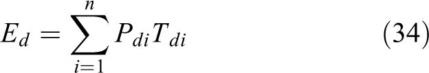
where
Navigation and control module
Similar to the communication and detection module, the average power of the navigation and control module can also be regarded as a constant, and the running time is a single cycle period. Then the energy consumption of the navigation and control module in a single cycle can be expressed as follows

where Pc is the average power of the module, T is the gliding cycle period, when the maximum gliding depth is H and the average gliding speed is v, and

Total energy consumption
Based on the above equations, the total energy consumption of the glider in a cycle can be calculated by the following equation

In general, we also need to study the energy consumption per gliding distance of the glider in a cycle, which can be expressed as

Simulations
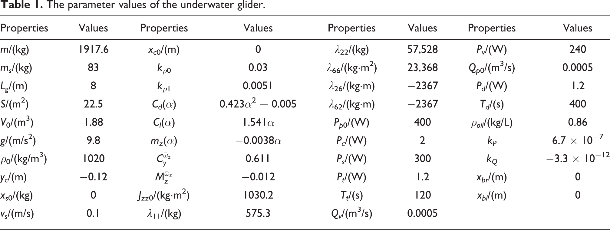
Given different initial values, the fourth-order Runge–Kutta method is used to solve the motion model, and the solved kinematic parameters bought into the energy consumption model to get the energy consumption of a cycle under different working conditions. Table 1 presents the specific parameter values of the underwater glider.
The parameter values of the underwater glider.
Different glide depths and glide ratios
In the simulation, the buoyancy adjustment is set to 80 L, then the energy consumption of one gliding cycle at different glide ratios and different depths is calculated. The total energy consumption is shown in Figure 4, and the total energy consumption per gliding distance is shown in Figure 5. The x-axis is the glide ratio, the y-axis is the depth, and the contour represents the total energy consumption per gliding distance.

Total energy consumption when the buoyancy adjustment is 80 L.
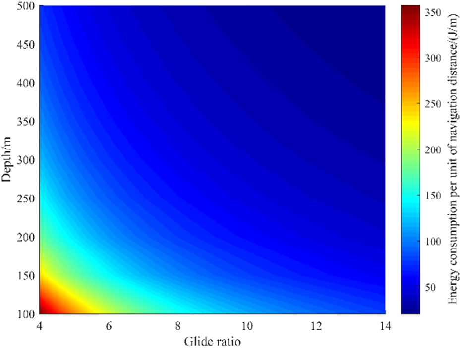
Total energy consumption per gliding distance when the buoyancy adjustment is 80 L.
According to Figures 4 and 5, we can see that the energy consumption during the attitude adjustment is independent of the gliding time, it is defined that the proportion of the energy consumption during attitude adjustment to the total energy consumption is η, so the low-energy glide strategy can be formulated based on η. The proportion η is shown in Figure 6
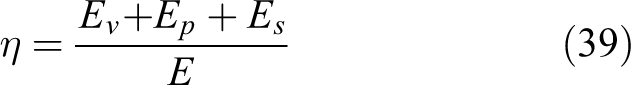

The proportion of the energy consumption during attitude adjustment when the buoyancy adjustment is 80 L.
From the simulation results, it can be seen that when the buoyancy adjustment is constant, the larger the glide depth, the larger the total energy consumption in a cycle, while the smaller the energy consumption per glide distance, and the smaller the energy consumption ratio of the attitude adjustment modules. With the increase of the glide ratio, the total energy consumption in a single cycle increases first and then decreases, the energy consumption per gliding distance decreases, and the energy consumption proportion of the attitude adjustment module decreases.
Different glide buoyancy adjustments and glide ratios
The glide depth is set to 500 m, and the energy consumption of one glide cycle is calculated at different glide ratios and different buoyancy adjustments. The total energy consumption is shown in Figure 7, and the total energy consumption gliding distance is shown in Figure 8. The proportion η is shown in Figure 9.
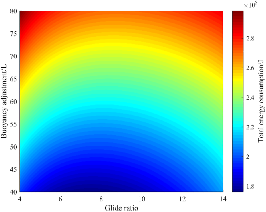
Total energy consumption when the glide depth is 500 m.

Total energy consumption per gliding distance when the glide depth is 500 m.

The proportion of the energy consumption during attitude adjustment when the glide depth is 500 m.
According to the above simulation results, when the glide depth is constant, the larger the buoyancy adjustment is, the larger the total energy consumption of single cycle, the energy consumption of per gliding distance and the energy consumption of attitude adjustment module are. While the larger the glide ratio is, the larger the total energy consumption of single cycle first increases and then decreases, the smaller the energy consumption of per gliding distance and the energy consumption of attitude adjustment module are.
Different glide depths and buoyancy adjustments
In the simulation, the glide ratio is set to 10, then the energy consumption of one gliding cycle at different buoyancy adjustments and different depths is calculated respectively. The total energy consumption is shown in Figure 10, and the total energy consumption per gliding distance is shown in Figure 11. The proportion η is shown in Figure 12.
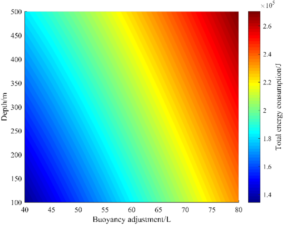
Total energy consumption when the glide ratio is 10.

Total energy consumption per gliding distance when the glide ratio is 10.

The proportion of the energy consumption during attitude adjustment when the glide ratio is 10.
From the simulation results, it can be seen that when the glide ratio is constant, the increment of the size of buoyancy adjustment leads to the increment of the total energy consumption in a single cycle, the energy consumption per gliding distance and the energy consumption ratio of attitude adjustment module. However, when the glide depth is increased, the total energy consumption in a single cycle is larger, but the energy consumption per gliding distance and the energy consumption ratio of attitude adjustment module are reduced.
Conclusions
Aiming at the blended-wing-body underwater glider, the motion model and energy consumption model of each module in a single cycle is established. Considering the working process of the underwater glider, the influence of different glide depths, glide ratios, and buoyancy adjustments on the energy consumption are analyzed respectively. The article plays a guiding role in designing and improving the energy consumption of the underwater glider. The main conclusions are as follows: As the glide depth is increased, the total energy consumption increases in a single cycle and decreases per gliding distance, leading to a smaller energy consumption ratio for the attitude adjustment module. As the buoyancy adjustment is increased, more energy is consumed in a single cycle and less energy is consumed per gliding distanced, resulting in a larger energy consumption ratio for the attitude adjustment module. With the increase of the glide ratio, the total energy consumption in a single cycle increases first and then decreases, the energy consumption per gliding distance decreases, and the energy consumption ratio of the attitude adjustment module decreases. Low energy consumption can be achieved by setting a larger glide ratio, a larger glide depth and a smaller buoyancy adjustment.
Footnotes
Declaration of conflicting interests
The authors declared no potential conflicts of interest with respect to the research, authorship, and/or publication of this article.
Funding
The author(s) disclosed receipt of the following financial support for the research, authorship, and/or publication of this article: The work was partly supported by the National Natural Science Foundation of China (Project No. 51979227).