
Abstract
This article deals with the mass estimation of an underwater glider with blended wing body subject to multiple constraints including strength, deformation, and stability in order to maximize its payload capacity and long range. Parametric modeling of the blended-wing-body underwater glider structure is implemented using Unigraphics (UG) secondary development. Finite element analysis is carried out to study the structural performance of the underwater glider using the commercial computational structural mechanics code ANSYS. Genetic algorithm based on the double surrogate model global optimization, which including polynomial response surface surrogate model and kriging-based surrogate model, is applied to the structural design optimization. The numerical results show that the optimized structure weight has been reduced by 10.816%, which proves that the optimization process is effective.
Keywords
Introduction
Underwater glider is a new type of autonomous underwater vehicle (AUV) which changes movement state by adjusting buoyancy and converts the lift on wings into propulsive force. Compared to the traditional propeller propulsion underwater vehicle, gliders have excellent hydrodynamic performance and cruising capacity which satisfy long-range and extended-duration deployments. The configuration of conventional underwater gliders is based on revolving body with fins and rudders, which have the characteristics of large volume and high compressive capacity, such as the Spray 1 and Seaglider. 2
For achieving higher hydrodynamic efficiency, blended-wing-body (BWB) configuration was used to the design of underwater gliders. This configuration has no clear dividing line between the wings and the main body of the craft, which provides higher maximum lift-to-drag ratio and lower wetted area to volume ratio. Jenkins et al. 3 have fully studied the feasibility of BWB underwater gliders. Office of Naval Research (ONR) 4 developed a BWB design model, “Liberdade XRay,” which is the world’s largest known underwater glider. The ZRay underwater glider was a modified form of the XRay underwater glider which completed in March 2010, having capacity of 1600 lb dry weight, 20-ft wing span, 1200–1500-km cruise range, maximum lift-to-drag ratio of 20, and operational depth of 300 m. 5 Sun et al. 6 designed a parametric geometric model of an underwater glider with BWB, and the shape optimization was carried out.
Structural optimization of aircraft with BWB configurations have been studied by many institutes.7–9 The first BWB designs proposed by Liebeck 10 used traditional skin and stringer arrangements. Mukhopadhyay 11 presented an efficient structural model development and design process of a mega transport BWB concept. Hansen et al. 12 proposed the structural analysis of BWB aircraft configurations using a physics-based mass prediction method. Cho et al. 13 presented the preliminary structural design and analysis of an ultra-heavy-lifting BWB military cargo transport. Gern 14 proposed a fast and flexible finite element model (FEM) for structural analysis, optimization, and weight calculation for BWB designs; Laughlin et al. 15 developed a physics-based multidisciplinary analysis and weight optimization environment for structural weight estimation of the BWB aircraft.
There may be no sufficient resources to analyze all of the combinations of variables that one would wish because finite element analysis (FEA) requires expensive computer simulations. Surrogate-based optimization (SBO) technology 16 can effectively reduce the number of expensive computational evaluations in global optimization. The SBO search process consists of the following steps: generating initial sample points, constructing surrogate model (SM), and infilling sampling criteria. Common methods used to construct a SM include polynomial response surface (PRS), adaptive and interactive modeling system (AIMS), 17 kriging, 18 radial basis functions (RBF), 19 and support vector regression (SVR). 20 Paiva et al. 21 compared three different SMs: quadratic-interpolation-based response surfaces, kriging, and artificial neural networks (ANNs) in multidisciplinary optimization problem for aircraft wing design. Sunny et al. 22 performed a curvilinear stiffened panel design optimization using an ANN residual kriging-based surrogate modeling approach. Liu et al. 23 developed an efficient kriging-based airfoil design system. Hao et al. 24 discussed cylindrical stiffened shells subject to non-uniform axial compression and internal pressure using surrogate-based optimum design with adaptive sampling.
This article considers a double surrogate model (DSM) global optimization process of minimizing the mass of BWB underwater glider. Section “Parametric model” presents the BWB underwater glider’s parametric shape model and structure model, respectively; section “Numerical analysis” focuses on structural numerical analysis using the commercial computational structural mechanics (CSM) code; section “Optimization problem” builds the optimization problem; section “Optimization methodology” introduces DSM optimization method based on PRS-SM, kriging-based SM and genetic algorithm (GA); section “Results and discussion” provides results and discussion; section “Conclusion” makes a summary and explains the direction for future work.
Parametric model
The design process of the BWB underwater glider can be divided into two stages: the shape design and the internal structure design. This article is from our series of works on the study of BWB underwater glider. The optimal value of shape optimization in Sun et al. 6 is used for structural optimization. The hydrodynamic performance of the BWB underwater glider was evaluated using the commercial computational fluid dynamics (CFD) code Fluent. The efficient global optimization (EGO) composed of kriging SM and expected improvement (EI) was used to solve the hydrodynamic design optimization.
Parametric shape model
In the design concept of the wing, three-dimensional (3D) shape is usually generated according to the characteristics of profile and spanwise contour line. Therefore, in this article, the shape of the underwater glider is described using two types of parameters: the planform shape parameters which describe the shape characteristics of the glider and the profile parameters which describe the spanwise profile shape.
Figure 1 shows the definition of the BWB’s planform using nine design variables. The planform can be divided into two sections: body section and wing section. The body leading edge (LE) and body trailing edge (TE) are shaped using B-spline curve to obtain smooth hydrodynamic surfaces. Each cure uses two control points. In Figure 1, bt is the half span of underwater glider which is set to 1250 mm in this article, ctip is the chord of wing tip, croot is the chord of wing’s root, ct is the chord of body root, α is the sweep back angle, d is the distance of wing’s root from glider’s nose, and n1, n2, and n3 are control points at leading edge and trailing edge.
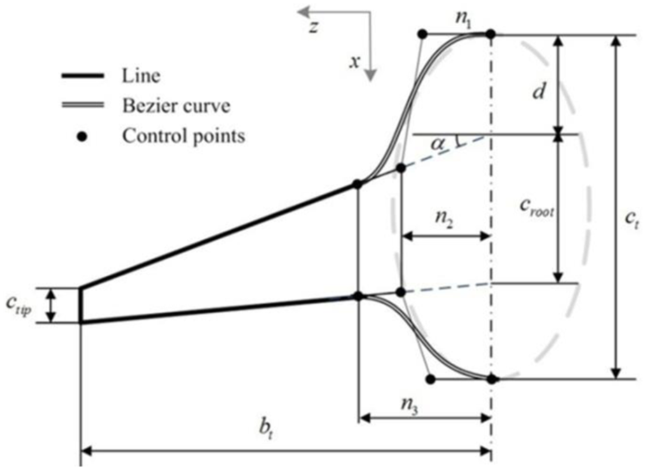
Definition of planform.
For BWB underwater glider, all of the cross-sectional profile shapes are airfoil. Since the glider does zigzag rising and diving movement in the water, typical symmetrical airfoil NACA 0012 is used. Parameters S1 and S2 control the maximum thickness of body cross-section and wing cross-section, respectively. Different combinations of airfoil can be selected by changing the values of the parameters S1 and S2. Parametric geometry model is shown in Figure 2.
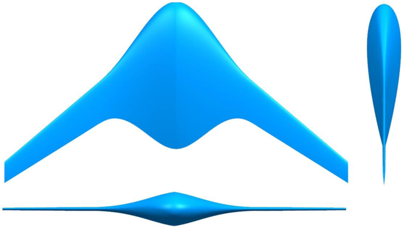
Shape of BWB underwater glider.
Parametric structure model
The task of structural design is to satisfy the requirements of strength and stiffness under the actual working conditions using the planform configuration parameters and the profile parameters received from the shape optimization design. This underwater glider designed with BWB configuration has a flat shape, and the compressive capacity is poor, therefore, non sealed structure with equal internal and external pressure is adopted. Because self weight and concentrated load of built-in equipment under working condition are the main factors of structure design, the glider uses semi-monocoque structure.
The BWB underwater glider can be divided into two parts: body section and wing section. The layout of structural components can be confirmed after determining the direction and magnitude of the force. Both sections have similar beam frame structure which contains ribs and spars.
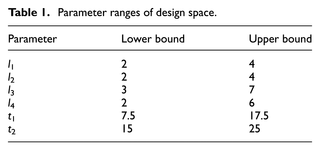
In order to simplify the analysis model, the number of ribs and spars is set to a fixed value, and the ribs and spars are equally spaced. In this article, the size of ribs and spars is primarily discussed and used as design variable. Figure 3 shows the definition of the BWB underwater glider’s internal structure using six design variables. Where l1 is the width of wing’s ribs, l2 is the width of wing’s spars, l3 is the width of body’s ribs, l4 is the width of body’s spars, t1 is the thickness of body’s ribs, and t2 is the thickness of body’s spars.
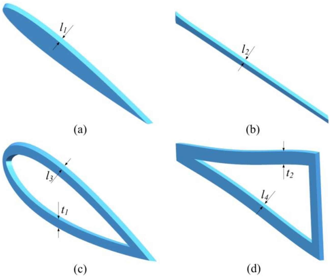
Definition of internal structure: (a) wing’s ribs, (b)wing’s spars, (c)body’s ribs, and (d) body’s spars.
Considering the actual situation and engineering requirements, the internal structure, structure arrangement, and overall structure of BWB underwater glider are designed as shown in Figure 4.
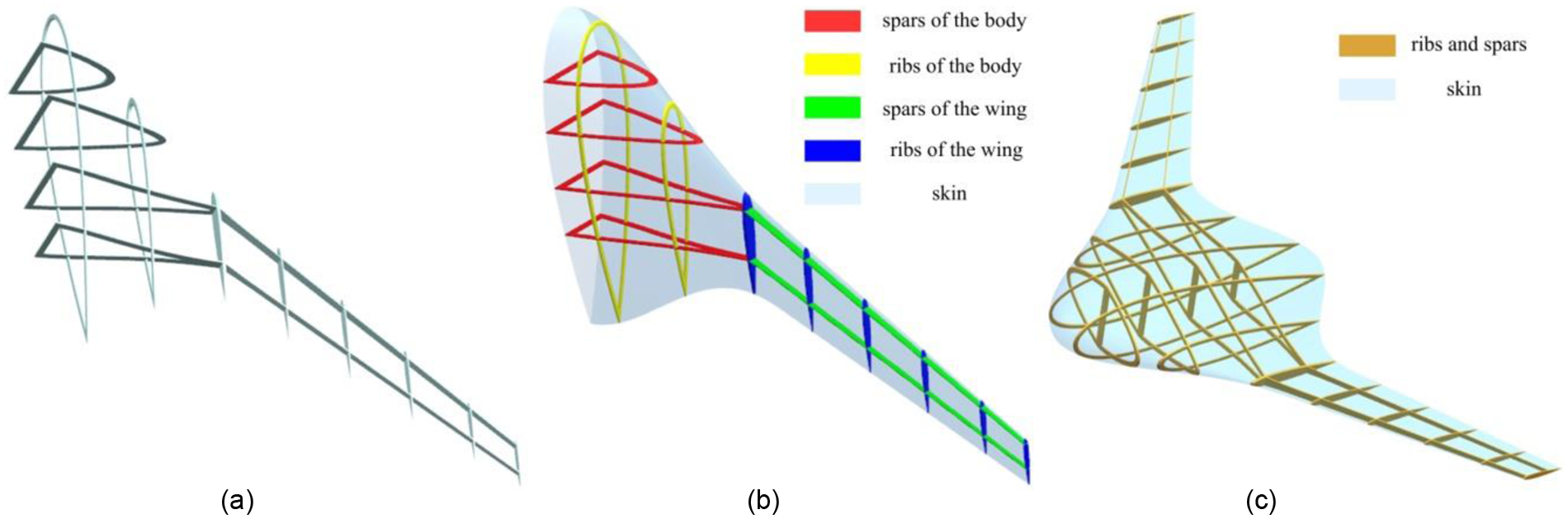
Structure of BWB underwater glider: (a) internal structure, (b) structure arrangement, and (c) overall structure.
Numerical analysis
The structural numerical simulations of BWB underwater glider presented in this article are carried out based on finite element method using the commercial code ANSYS. There are three responses taken into account to evaluate underwater glider structures: maximum von Mises equivalent stress, maximum deformation, and buckling factor. Structural steel material is used with isotropic elastic Young’s modulus of 200 GPa, Poisson’s ratio of 0.3, and density of 7850 kg/m3.
In order to reduce the computational cost, we take half of the BWB underwater glider for FEM analysis since it is completely symmetrical. Because the glider is subjected to symmetric and equal loads on both sides and the resultant force at the plane of the whole glider is zero, the symmetry plane is set as the boundary constraint of the FEM. The constraint type is fixed in order to ensure that there is no displacement and torsion in the symmetry plane.
The glider’s load is divided into three parts: (1) hydrodynamic force, which distributes on the upper and lower skin of the glider; (2) self structure weight, which loads with inertia force; and (3) load of equipment, which is composed of concentrated load and uniformly distributed load. The concentrated load is formed by control system, gravity adjusting structure, chain, and other equipment on the fixed position while the distributed load is produced by the buoyancy material distributed on the surface of the glider.
Structured grids with hexahedral cells are used in all the calculations. FEM of BWB underwater glider is shown as Figure 5.

FEM model of BWB underwater glider.
Optimization problem
Design variables
Based on section “Parametric structure model,” we can know that there are six variables in structure design. According to the parametric structure design of BWB underwater glider, Table 1 shows the parameter ranges of each design variable.
Parameter ranges of design space.
Constraints
The structural optimization design of underwater glider with BWB is a multicriteria constrained optimization problem; the hydrodynamic and structural requirements should be well satisfied. Three constraint conditions are mainly taken into account in this article: the maximum von Mises equivalent stress, the maximum deformation, and the buckling factor, which represent the strength, stiffness, and stability design requirements, respectively:
The stress criterions should be considered to ensure the strength of the BWB underwater glider

where σmax represents the maximum equivalent stress, σs = 330 MPa is the yield stress, and γ1 = 1.2 is the stress safety factor.
The maximum deformation should be less than the given value

where dmax is the maximum deformation, and bt is the half span of underwater glider.
The buckling load should be greater than ultimate loads in order to avoid buckling failure

where n is the lowest buckling factor, and γ3 = 1.5 is the safety buckling factor.
Objective function
In order to satisfy payload capacity and long-range design, the minimum mass of BWB underwater glider structure is taken as the objective function. The mass of the structure is determined from the volume of the finite element structure (FES). The objective function is given as follows

where
Optimization methodology
PRS-SM
PRS makes predictions by constructing a polynomial model using least square fitting. First-order and second-order polynomial functions of PRS method have the following forms
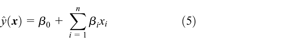

where the parameter n represents the number of design variables, βi is the univariate polynomial coefficient, βii is the bivariate square term coefficient, and βij is the bivariate cross term coefficient.
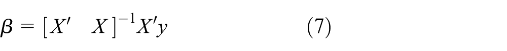
where X is the design matrix of the sample points, y contains the response values of all the sample points, the PRS is easy to construct, and the smoothness of the function contributes to the rapid convergence of the noise optimization problem.
Kriging-based SM
The kriging approach was proposed by Krige 25 and later widely used for surrogate modeling.26,27 Kriging uses a generalized Gaussian equation as the basis function, which is a special form of an RBF interpolation. The function allows variation in the response from variable to variable and is more statistically based than a pure Gaussian function. The kriging predictor and its estimated mean square error (MSE) function have the following forms

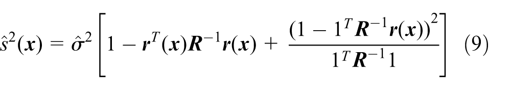
where
GA
GA 28 is based on natural selection theory which only uses the value of objective function without the gradient information. This feature makes GA become an efficient search mechanism for structural optimization design (Figure 6).
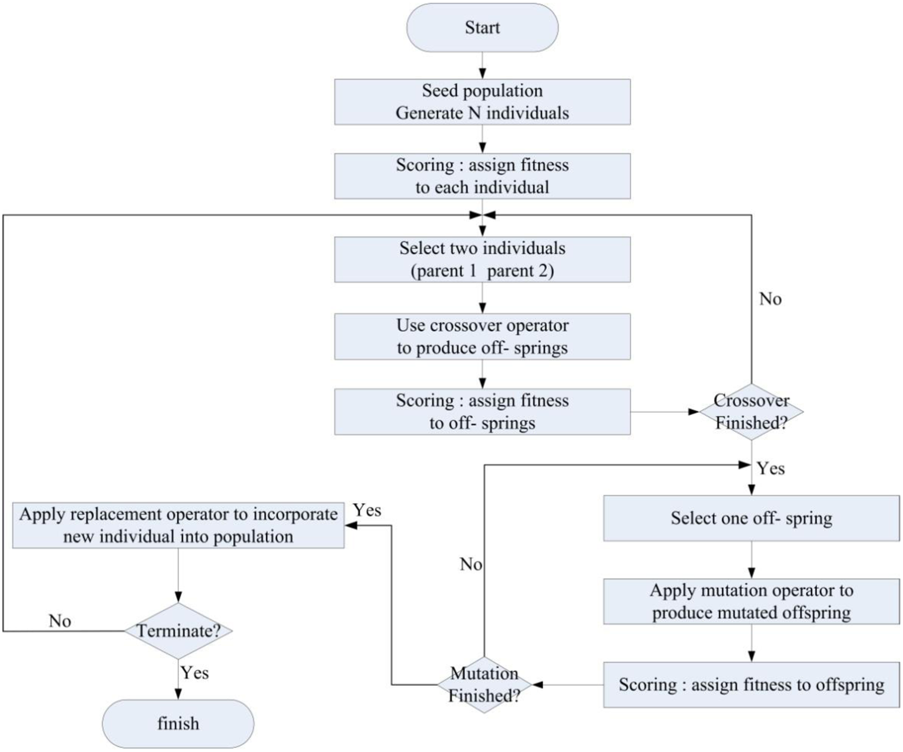
Flowchart of GA.
The procedure of GA can be shown as follows:
Generate random population of n chromosomes.
Evaluate the fitness f(x) of each chromosomes x in the population.
Create a new population by repeating following steps until the new population is complete.
Use new generated population for a further run of the algorithm.
If the end condition is satisfied, stop and return the best solution in the current population.
Return to step 2.
DSM optimization
The complete DSM global optimization process including the following steps, and the flowchart is shown in Figure 7.

Flowchart of the optimization process.
The initial process:
Generate N sample points over the entire design space applying optimal Latin hypercube sampling (OLHS) method.
Carry on FEA using the N sample points and store the results.
Initialize the samples database based on their computational values.
The loop process:
4. Construct objective and constraint functions of the kriging-based SM and PRS-SM, respectively.
5. Obtain the global optimal solutions of the two SMs by GA, respectively.
6. Perform FEA at the two optimal solutions.
7. Add the two optimal solutions to samples database.
8. Update the two SMs and repeat the steps 4–7 until complete 60 iterations.
Results and discussion
In this article, the initial 60 samples are selected by OLHS, and the performance of 60 samples is evaluated by the CSM code ANSYS. The best feasible solution in the 60 samples which satisfied the constraint conditions is adopted as the initial design point. The initial PRS-SM and kriging-based SM are constructed based on these 60 samples’ data, respectively. Then, GA is used to optimize the structure based on both models and two current optimal solutions were added to the samples in each iteration process. Finally, after 60 iterations, the best feasible solution satisfying the constraint conditions is chosen as the optimal design point.
Table 2 shows the structural performance comparison of the initial design and the optimal design. The mass of the optimal design is 5.409 kg, and it is 10.816% lower than the initial design. The detailed FEM analysis result is shown in Figure 8.
Optimization results: comparison of structural performance.


Structural analysis of the initial and optimal design.
As expected, the results of the initial design together with the optimal design satisfy the constraints. The maximum von Mises equivalent stress, maximum deformation, and buckling factor of the optimal design are closer to the constraint values than that of the initial design. Figure 9 shows the relationship between mass and the number of added points, and the correspondence between current optimal feasible solution and the iterative number is presented in Figure 10.

The relationship between mass and the number of added points.

The relationship between current optimal solution and the number of iterations.
With the progress of iterative process, the number of feasible solution increases, and the current optimal feasible solution is obviously getting better. This result shows that parametric modeling, finite element method analysis, DSM, and GA optimization process successfully optimize the structure of BWB underwater glider.
Both the maximum von Mises equivalent stress and maximum deformation of the optimal BWB underwater glider structure are very close to the constraint values while the buckling factor is much higher than the constraint value; therefore, von Mises equivalent stress and deformation are mainly discussed. Figure 11 displays the relationship between maximum von Mises equivalent stress and the number of added points while Figure 12 illustrates the correspondence between maximum deformation and the number of added points. We can find that the maximum von Mises equivalent stress gradually converges as the number of added points increase. The maximum deformation approximates convergence at the beginning of the iteration. A large part of the solutions become infeasible because they exceed the upper limit of the von Mises equivalent stress constraint.

The relationship between maximum von Mises equivalent stress and the number of added points.
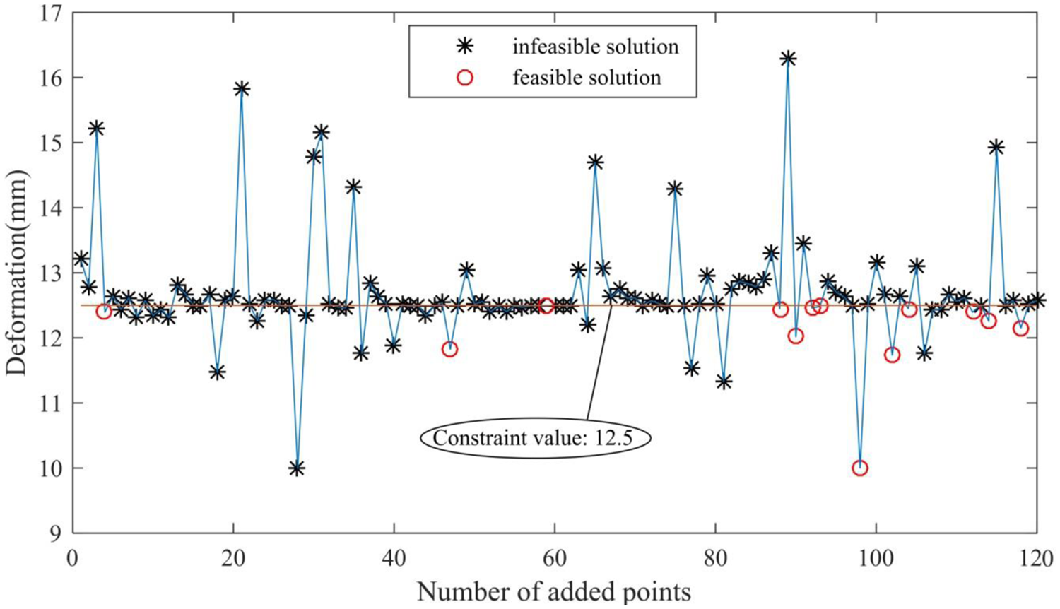
The relationship between maximum deformation and the number of added points.
Single SM has great difference and unpredictability for different optimization problems, which brings some risk to engineering optimization. DSM optimization method can greatly reduce this risk. Compared to single SM, DSM optimization method shows higher accuracy and stability in prediction.
Conclusion
In this article, structural optimization of underwater glider with BWB using parametric modeling, finite element method analysis, DSM, and GA optimization is presented. The parametric shape model consists of 10 design variables, and the optimal value of shape optimization is used for structural optimization. The parametric structure model contains six design variables. The structural optimization is performed in an iterative way. Each iteration adds two current optimal solutions generated by the kriging-based SM and PRS-SM, respectively. Perform FEA at the two optimal solutions, then add the results of the two optimal solutions to samples database. According to the actual computational resources, the number of iterations is set to 60. The maximum von Mises equivalent stress and the maximum deformation approximate converge at the end of the iteration. The mass of initial design is obviously decreased in this optimization process. The results show that the structural performance of the BWB underwater glider is significantly improved. Increasing the number of variables, testing of other SMs and algorithms will be studied in the future work.
Footnotes
Academic Editor: Davood Younesian
Declaration of conflicting interests
The author(s) declared no potential conflicts of interest with respect to the research, authorship, and/or publication of this article.
Funding
The author(s) disclosed receipt of the following financial support for the research, authorship, and/or publication of this article: This research was supported by the National Science Foundation of China (Grant No. 51375389) and the Doctorate Foundation of Northwestern Polytechnical University.