
Abstract
This article describes the development of an unmanned aerial vehicle system that had a remarkable performance in the 6th International Unmanned Aerial Vehicle Innovation Grand Prix, which was held on November 2–4, 2018, in Anji, China. The main mission of the competition was to build a simulated tower using prefabricated components by an unmanned rotorcraft, which could be decomposed into the following four subtasks: (1) navigation and control, (2) recognition and location, (3) grasp and construction, and (4) task planning and scheduling. All the tasks were required to perform autonomously without human intervention. According to the requirement of the mission, the unmanned aerial vehicle system was designed and implemented with high degree of autonomy and reliability, whose hardware was developed on a quadrotor platform by integrating various system components, including sensors, computers, power, and grasp mechanism. Software algorithms were exploited, and executable computer codes were implemented and integrated with the developed unmanned aerial vehicle hardware system. Integration of the two provided onboard intelligence to complete the mission. This article addresses the major components and development process of the unmanned aerial vehicle system and describes its applications to the competition mission.
Introduction
With the development of computer capabilities and artificial intelligence, unmanned vehicle systems technology have been considerably improved over the past several decades. Among various types of unmanned vehicle system, unmanned aerial vehicles (UAVs) or unmanned aircraft systems (UASs) have attracted a great deal of interest for their capacities to execute dangerous and difficult missions ranging from military to civil application in the air environment. 1,2 However, most existing UAVs are still remotely controlled by human operators with continuous intervention, which implies that they are not “unmanned,” let alone autonomous. In order to increase the autonomy level of unmanned vehicles and reduce human intervention, a number of efforts and researches have been made. 3,4
In order to keep up with the trend of research, the Unmanned Aerial Vehicle Innovation Grand Prix (UAVGP) hosted by Aviation Industry Corporation of China was held on November 2–4, 2018, in Anji, China. Thirteen teams from different regions participated in the competition. Figure 1(a) shows the competition course layout. In brief, the contestants were required to design an unmanned rotorcraft to autonomously transport building components (which was simulated as a box in the competition, see Figure 1(b)) from one platform (which was called structure repository) to the other (which was called building site) and stack them up as high as possible. To complete the predefined mission, we designed and implemented a UAV system that had a multilayered autonomy capacity. Respectively, low level of autonomy required the UAV to have the basic abilities of autonomous takeoff and landing depended on its control and navigation system. Intermediate level of autonomy needed the help of external perception sensors and mechanical structure to perform more complex operations, including target recognition and positioning, component capture and placement. High level of autonomy includes tasks and routes planning, which provided top-level commands and guidance for the whole system. Manual intervention was prohibited throughout the process, which made the onboard intelligence be a key factor to perform the mission. More broadly, these mission tasks were designed in consideration of the potential real-world applications of UAVs, for example, the UAV transport of express industry.

Arrangement of the competition. (a) Schematic diagram of competition field (about 50 m × 40 m). The UAV transported the components from the component repository to the building site. At last, return to the origin takeoff point to land. The position and number of the components were random. (b) The building component (be simulated as a box): 1 m × 0.25 m × 0.5 m. There were logos that retained unknown before the competition in the surfaces of the box. The color of the box was blue. UAV: unmanned aerial vehicle.
The team from Shenyang Institute of Automation, Chinese Academy of Sciences, participated in the competition and developed a sophisticated UAV system based on a quadrotor platform. The Micro Electromechanical Systems and propulsion systems were designed and integrated by using commercial off-the-shelf components for efficient and reliable system development. An autopilot system named PIXHAWK was adopted as the flight controller, which integrates an inertial measurement unit (IMU, consists of an accelerometer and a gyroscope), a magnetometer, a barometer, and some redundant electronic components. Various external sensors were manually installed on the UAV to achieve perceptive capability and autonomous navigation. A binocular camera was used for recognizing object and acquiring their relative positions with respect to the UAV. A differential GPS (DGPS) was used to obtain global positioning information of the recognized objects. Some other sensors such as distance sensor was used for low level altitude control and obstacle detection. Accordingly, distributed executable programs were developed upon different computers to provide real-time perception, precise navigation, control, and mission planning by integrating the measurements form the above sensors. All the computer codes were implemented in C++/python.
The main contributions of the article are: The detailed procedures of designing an autonomous UAS that could recognize, grasp, transport, and place the components elegantly, which can be used as a reference to design a similar UAS when facing an object transfer task. A novel grasping strategy, including grab, emergency, and fault-tolerant mechanisms, was presented to capture the components safely, efficiently, and accurately.
The remainder of the article is organized as follows. The second section presents the major components of the UAV system, which includes the hardware and software modules. The mission strategies were described in the third section and the corresponding performances in actual environment were presented in the fourth section. Finally, the conclusion of the study was illustrated in the fifth section, along with some discussions on related technologies.
UAV system development
Design requirement
As described in the study by Clough, 5 to endow the UAV with high degree of autonomy, there are some basic challenges to cope with, such as perception and security issues. Given the specific task, we need to consider the following aspects.
Considering that the UAV was needed to carry a heavy load (see Table 1) during flight, general small-scale UAVs were not competent because of poor load ability. In general, however, limited by current battery technologies, large-scale electric UAVs are often associated with endurance problem. Additionally, because the components are so large that their upper surfaces will discourage the propagation of the downward airflow produced by the propellers of UAV, which would result in that the lift force is smaller than carrying a smaller object of the same weight. Therefore, the actual load capacity of the UAV is much smaller than the rated load capacity, which put forward higher requirements for load capacity.
The load the UAV carried.

UAV: unmanned aerial vehicle; IMU: inertial measurement unit; DGPS: differential GPS.
The capacity of grasping component accurately was the core of the whole system. As Figure 1(b) shows, the component was too large to use ordinary grasp mechanism. Therefore, a novel grab mechanism owned the property of grasping and putting the component easily was required.
Precise navigation was a fundamental capability to perform the given tasks using the UAV. As required by the mission tasks, the UAV was needed to grasp components and transport them to the building site to stack, which meant large location error which would make the UAV deviate from the component was unallowed.
The control capacity was another crucial part of the UAV development. Considering the high nonlinearity and underactuated motion property of the UAV, a control technique that performs well in practice was required. During the mission, the load weight would change, and gust disturbance might occur. Therefore, the control performance was required to be robust and stable.
The perception of the surroundings was considered as the core to perform the competition. It was because the positions of the component were not given in advance, namely, the UAV was required to identify and locate the components actively. To improve the success rate of grasping, an integration of hardware and software that possessed high identification efficiency and location accuracy was required.
Power and emergency system was required to carry out the mission with high security. During the competition, some emergencies might occur due to the hardware failures and logic errors, so a multilayered emergency system was required to protect the UAV and its surroundings.
UAV system component
Although some requirements described above were not purely about software or hardware, they are divided into these two parts to describe for clearness. Figure 2 shows the developed UAV system and its hardware architecture is described in Figure 3. We chose the quadrotor over the single rotor helicopter mainly because of its maneuverability. 6 The hardware system of the developed UAV comprised five subsystems: (1) flight system, (2) perceptual system, (3) computer system, (4) grab system, and (5) a power and emergency system, which were corresponding to the design requirement above. Details of these subsystems are described below.

The developed UAV. Various sensors were mounted on it to provide accurate navigation, control, and perception. UAV: unmanned aerial vehicle.

The hardware structure of the designed UAV. The whole system comprised five subsystems: (1) flight system, (2) perceptual system, (3) computer system, (4) grab system, and (5) a power and emergency system.
Flight system
The flight system provided essential propulsion, control, and navigation module. A trade-off was made between load capacity and endurance ability when selecting the flight platform. Four identical motors whose maximum pull was 14 kg per axis were installed on the airframe. For long endurance, two 6S Li-Po batteries, 16,000 mAh each, were mounted on the UAV, which made the endurance of the UAV system reached 11 min with load weight approximately 8 kg. An IMU and DGPS provided vehicle motion information in the high-frequency and low-frequency range, respectively. The complementary navigation system by combining IMU and DGPS would yield accurate navigation information, which enabled the UAV system to successfully perform the mission task. And the DGPS and the UAV were connected by wireless transmission module whose operating frequency is range from 840 MHz to 845 MHz and maximum power is 100 W.
Perceptual system
The perceptual system obtained the three-dimension position of the components and determined its current state by interacting with the environment. In addition to the navigation sensors, the perceptual system included additional two parts: vision system and ultrasonic distance sensor.
The vision system was used to acquire the accurate position of the components, which consisted of a downward-looking binocular camera and an onboard computer. The connection between the binocular camera and the airframe was rigid to keep the relative position between them be constant, which was required by subsequent coordinate transformation.
The distance sensor also installed downward to measure the distance between the UAV’s bottom and the object. The measurements were used as criteria to judge whether the component has been captured or placed successfully later.
Computer system
A computer system apart from the flight controller contained two onboard PCs and an external PC was used to handle the vision measurement, issue command, and conduct real-time display. The vision PC was required to have enough computational capacity to process the computer vision measurement data acquired by the binocular camera in a frame rate of 10 fps. Another computer onboard was used for task planning and scheduling, that is, acquired the current status of the UAV then perform the appropriate action depend on it. The external computer was used to run the ground station (GS) program, whose function was to display important real-time information of the UAV and execute some essential operations. Based on the consideration above, the computer system was designed to consist of three separate computers, and their configuration is shows in Table 2. The two onboard computers needed to work reliably under various environment disturbance due to vibration impact, heat, and operational uncertainty. These three computers along with the flight controller were connected via serial communication. And the data transmission frequencies between different computers, including the flight controller, are showed in Table 3.
The configuration of three computers.

Data transmission frequencies between different computers.
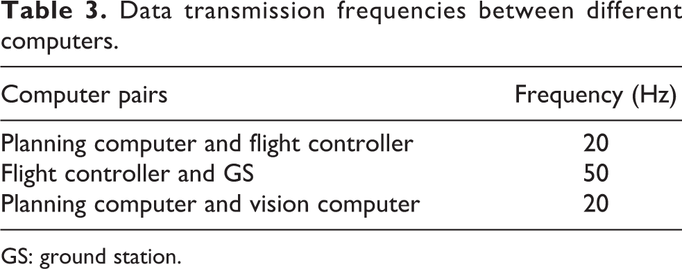
GS: ground station.
Power and emergency system
All the devices onboard, including computers, sensors, and propulsion system, were electrically powered by batteries. Two 22.2 V Li-Po batteries were used in parallel to provide power for propulsion, and an additional 22.2 V battery was used to provide power for computers and sensors. The power system for propulsion was designed to be separate from the sensor and computer systems in order to reduce any interference and noise. The expected endurance of the UAV power system was 11 min; however, the endurance could vary, depending on the operating conditions. To guarantee high security of the UAV during mission, multilayer mechanisms were used to handle the emergency, including a hard stop switch to quit the motors, a mode switcher to operate the UAV manually, and a soft state switcher to change the current state of the UAV on the GS.
Grasp system
Figure 4 demonstrates the grasp system used to grasp the components. Considering the size, shape, and surface of the components, a novel mechanism to perform the grasping action was designed and implemented. Six suckers in total were divided into three groups, and each of them could work separately to increase the success rate of grasping. Two different kinds of pump were used to provide suction and deflation, which corresponded to grasping and dropping. This had the components grasped and put easily. A servo was used to switch open and close status of the pumps depending on the current state of the UAV.

The grasping system. (a) The scalable device was in its original length about 15 cm. (b) The scalable device was compressed to about 5 cm. The difference between the two made up for the navigation error.
Due to the system error of hardware devices and existence of stochastic errors, the navigation deviation could still reach 10 cm even used DGPS and tuned the parameters to almost optimal. To compensate for the positioning error, a scalable device whose length could vary from 5 to 15 cm according to the different magnitudes of the contact force was applied. Once the UAV touched the components and continued to descend, the device will gradually shrink from natural length, which ensured both the stability of the UAV and the success rate of grasping.
Software structure
The software structure of the developed UAV system is graphically demonstrated in Figure 5.
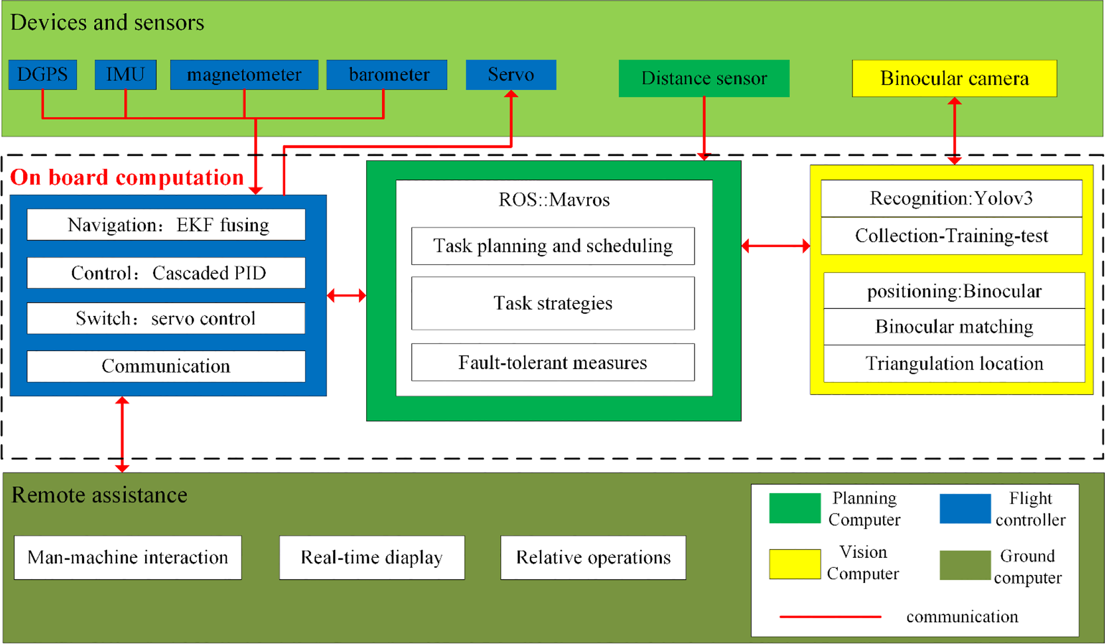
A schematic diagram of the software structure. The software system mainly comprised the top-level programs for task planning, the middle-level of computer vision, the bottom-level of control and navigation, and the GS program. GS: ground station.
As shown in the Figure 5, the software structure could be divided into four main components: (1) The programs ran in the flight controller, including guidance, navigation, and control, which provided the lowest level of autonomy. (2) The vision programs played the role of perception, which was used to get the relative position of the component with respect to the camera. This provided the intermediate level of autonomy. (3) The task planning and scheduling programs that directed the whole mission by defining the corresponding action for each state. It provided the highest level of autonomy. (4) GS program that provided the human–machine interaction that can conduct some necessary operations and display. It provided assisted autonomy.
The programs ran within the flight controller mainly played the roles of guidance, navigation, and control. By receiving the control commands from the planning algorithms, the UAV was required to perform specified actions such as ascending, descending, hovering, panning, rotating, and possibly combinations thereof. Meanwhile, the current position and attitude information of the airframe measured by onboard sensors was packed and sent to the planning PC to determine the current status of the UAV.
The vision programs were implemented to perceive the surrounding environment. A binocular camera was used to get the image data of the environment at a speed of 10 fps. Later, these images were used to get the three-dimension coordinate information of the components. The processing of camera measurements was handled by a separate computer system owing to the large computational load. This separate computer handled computationally expensive data processing jobs, and the processed data, that is, the relative positions of the observed object, were delivered to the task planning PC via the serial communication. An ultrasonic distance sensor was used to measure the distance between the UAV and the obstacle. All the sensor measurements were shared among several computers through communication. The task planning and scheduling programs could be regarded as the main program of the software structure. It was designed to supervise all the other programs and modules, that is, received the return data of them and published commands to them. It was the program that endowed the UAV system with the autonomy to perform the mission tasks efficiently and reliably.
GS program was essential for operators, because it was important to master its current situation when the UAV was carrying out the mission tasks. In addition, it could execute some emergent operations, such as status switching, to avoid some disastrous consequences. The GS and the flight controller were connected by wireless data transmission module.
Mission task strategies
Some limits and requirements were given to the UAV system by the competition organizing committee and current technical level, including The maximum endurance of the UAV system was about 11 min, which is limited by current state of art. The score of the competition depended on the height stacked by the components. The higher the stack, the higher the score. Full autonomous flight, including takeoff, landing, recognition, positioning, grasping, transport, stack, planning, and so on. The final score would be zero once the UAV flew away from the safe area.
Obviously, these requirements and limits directly determined the UAV system should be designed to be time-saving and secure. As for the underlying control and navigation, it should be stable and accurate with small deviation, overshoot, and settling time. For the task planning, it should be efficient to stack more components in finite time, which required fast recognition and positioning for the objects, more efficient grasping and path planning. The following gives the details of the applied strategies.
Navigation and control
No matter what mission the UAV was carrying out, the part of navigation and control is always the most fundamental. The navigation and control algorithms of a UAV system commonly comprise two part: attitude solution and attitude control. In the following section, these two parts will be presented according to the order.
Navigation
In order to acquire more accurate attitude information, various essential onboard sensors were integrated to the flight controller. A gyro provided vehicle angular velocity information in the high-frequency, and an accelerometer provided accelerated velocity information in the low-frequency. The two could complement for each other. A magnetometer was used to estimate the current orientation of the UAV. The measurements from different sensors were required to merge to figure out the attitude of the UAV. Generally, there were three main algorithms to calculate the attitude of the UAV: (1) explicit complement filter, 7,8 (2) gradient descent, 9,10 and (3) extended Kalman filter (EKF). Considering the UAV would have a sudden acceleration and deceleration frequently, and the attitude fluctuated greatly because of the wind and varying load, the EKF was selected because of its better dynamic performance, although it has greater computation complexity. Dual-subsample rotation vector method was used to calculate the optimal estimation of attitude from the measurement data, which turned out to be robust and accurate even in the case of dynamic condition. With setting appropriate parameters of EKF, the accuracy can reach 1° for attitude, and 2 cm for position. In addition, this combination was also used for velocity and position prediction, in which the DGPS provided position observations used for state correction. In some situations, where the DGPS signal would be lost, a barometer is used as a backup for height estimation.
Control
The quadrotor is a typical underactuated system, although this brings convenience to the design and implementation, it caused problems in control due to the nonlinearity of the system and the coupling of variables. The following state vector can describe the UAV’s motion

where x, y, and z represent the position of the UAV in the local north-east-down (NED) coordinate system. vx
, vy
, and vz
are the UAV’s velocity in the same coordinate system. θ, ϕ, and ψ are the orientation in Euler angles, while

The cascaded PID controller structure for the designed UAV. The outer loop was the position and velocity controller. The inner loop was the attitude and angular velocity controller. The feedback variables were calculated from the measurements of onboard sensors. PID: proportional–integral–derivative; UAV: unmanned aerial vehicle.
Recognition and location
In the competition, the components’ position coordinate were not given in advance, so the UAV was required to find them. The accurate three-dimension coordinate of one of them should be given to the UAV for subsequently grasping. The computer vision algorithm was integrated with a binocular camera to achieve the goal of object identification and positioning in the designed UAV system.
Recognition
The existing algorithm for target recognition can roughly divided into two categories: one is the traditional, 11 –15 the other is deep learning based. The traditional methods have faster detection speed and lower computational complexity, but with lower precision. Deep learning-based algorithms mainly include the following: Methods based on region proposal whose typical one is Faster R-CNN 16 ; regression-based approaches, such as Yolo-v3 17 and Single Shot Multibox Detector. 18 Having a relative high precision is one salient feature of these methods. For the given mission of grasping a component, compared to the speed, the identification precision was given priority. Considered comprehensively from speed and accuracy, the Yolo-v3 algorithm was selected to perform the recognition mission.
To achieve the goal of identifying the component successfully, a three-step procedure was executed (see Figure 7).
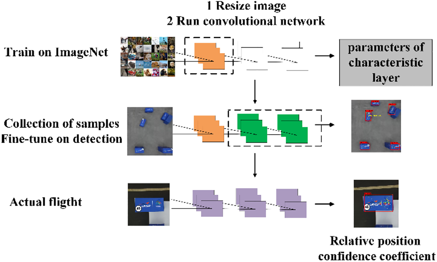
The process of component identification process in actual flight.
First, collected and labeled training samples. Here, the training samples were the images of component at different situations, including different angles, scales, and layouts. To collect the required samples, we manually operated a UAV with a camera and made it hover at different altitudes to collect samples. Then we would label them manually. Thanks to that we can use ImageNet to obtain a pretraining model, 19 the number of samples that used to train the model is reduced to a few hundred, which avoided lots of manual labeling.
During this step, some details were required to pay attention to. One was that the varying lighting condition in outdoor environment caused a lot of difficulties in detecting the components. Another one was that the layout of the components was so dense that the interval between the adjacent two was only 20 cm, which would result in confusion during identification because of the effect of the sides of components. For the two problems, two measures were taken. For the former one, increasing the complexity and richness of the samples. The richer the training samples, the more robust the actual performance. For another, the combination of coarse positioning and fine positioning was used to improve the accuracy of identification and positioning, which will be explained after location part.
Second, trained the model. The pretraining model trained by ImageNet was incomplete for our mission. To make the model valid for the given target, it was required to be trained by the labeled samples obtained above to acquire the expected parameters. During the training process, the component was the only one class of object. Generally, the training time was usually about 1 h on the vision computer.
Last, tested the model. This was to validate the performance of the trained model in the actual environments, especially the recognition accuracy. If the actual performance of the model was unsatisfied, the model was required to be retrained by increasing or replacing the training samples until the performance was good enough. Additionally, the algorithm also provided a confidence coefficient which denoted the probability that a recognized object was a component, which was a crucial parameter to adjust to balance underfitting and overfitting in practice.
Location
A downward-looking binocular camera was mounted on the UAV system to position the components. The vision-based target location technology mainly includes the following three kinds: (1) Monocular vision-based positioning technology. 20 (2) Structured light technology. 21 (3) Binocular vision-based positioning technology. 22 Compared to the former two, despite the lower speed result from the image conversion and binocular matching, the binocular camera was a better choice for the competition because of its higher positioning accuracy and the ability of stable performance in outdoor environment. Figure 8 demonstrates the principle of binocular ranging and give the formula.

Schematic diagram of binocular ranging.
In the designed vision system, the binocular camera first figured out the coordinate information of every pixel point under the camera coordinate system through binocular matching and triangulation; Next, the same image would be given to the recognition algorithm to find out the objects, and the coordinate information of the four vertices of the enclosing rectangle of the objects will be given once the target object was identified successfully. Finally, the three-dimension coordinate information
The guidance coordinate system been used by the UAV is the local NED, so the given coordinate information

where Re
and Rb
denotes the

where

The procedure of the coordination coordinate transformation. The rotation between camera coordinate systems and UAV body coordinate system is fixed and measured manually. The rotation between UAV body coordinate systems and NED coordinate system is measured by IMU. UAV: unmanned aerial vehicle; NED: north-east-down; IMU: inertial measurement unit.
Measures to improve positioning accuracy
Some measures were applied to the part of positioning to increase the accuracy, including 1. The combination of the coarse positioning and the fine positioning. In order to obtain larger field of vision that had the potential of containing more components, the UAV was required to be further away from the component repository, which would result in lower location accuracy because of the longer distance. The contradiction between the size of the perceived region and the positioning precision generated the hierarchical positioning strategy. First, the UAV observed the component repository from a higher altitude to have a larger field of vision. If the component was identified in this field, a rough position would be given.
Next, depending on the rough position information, the UAV got close the component to acquire a more precise location. Generally, the component that obtained by the two processes would be the same. The whole positioning process is graphically described in Figure 10.

The positioning process. First, to obtain a larger field of vision, the UAV was in a relative high attitude. Then, it would descend to a low altitude to get a high positioning. UAV: unmanned aerial vehicle.
2. Incremental average of the coordinate information. Inevitably, there would be errors in the measurements resulted from the airframe vibration and random error. The incremental average approach described below was used to decrease the error

Here,
3. Yaw adjustment of the UAV. The heading angle of UAV was required to be paralleled with the long side of the component to acquire the best positioning results. The actual attitude of the UAV was shown in Figure 11(a), and the one in Figure 11(b) was the required. The coordinates of the four vertices of the enclosing rectangle acquired by the binocular camera were used to figure out the angle α that guided the UAV to adjust its yaw to the required. Here, the coordinates of the four vertices of the enclosing rectangle were

where

or


The process of yaw adjustment. The red rectangles represent the attitude of the UAV. UAV: unmanned aerial vehicle. (a) The yaw angle of the UAV relative to the component before adjustment. (b) The yaw angle of the UAV relative to the component after adjustment.
Based on the angle α, the attitude represented by quaternion was sent to the flight controller as an expected value to which rotate the airframe.
Capture and construction
Capture
Suckers made of soft silicone were used to perform the grasping mission. Based on the coordinate acquired by the binocular, the suckers could usually reach the upper surface of the components. However, there were still some problems to be solved before the UAV had stable performance in grasping. First, one thing came out of the experiment was that when the UAV reached the expected target point, it would have a dynamic balance, which might bring difficulty in grasping due to the UAV deviated from the center of the components. Therefore, the expected target point should be changed to somewhere under the actual one acquired by the binocular. However, this resulted in the contact force between the UAV and the component became bigger and then the airframe would be unstable and even dump, so some protection mechanisms were designed, for example, the UAV’s descent time was limited. This strategy solved a troublesome issue that had kept unsettled for a long time.
Second, how to judge if the component was successfully grabbed or not. Due to the misjudgments resulted from the existence of dead zone and the similar scenarios, the vision system was incompetent. So, a distance sensor was used instead. After the grabbing action, the UAV would rise to a certain height at which to judge the relation between the measurement and the predefined threshold. The grabbing action would be conducted again until the component was grasped successfully.
Construction
The main work of construction was to adjust the three-dimension position of each component during the placement process. The UAV followed the planned path to the target position which was 5 m above the building site, then kept descending until the component contacted with the ground to ensure that its position would not vary too much. Similarly, the distance measurement was treated as the criteria to judge if the component was placed successfully. The UAV would go back to the component repository again to grasp the box once the component was placed successfully.
Task planning and scheduling
The goal of the competition was to complete the mission autonomously. Once the competition started, manual intervention to the UAV was forbidden. The UAV needed to be capable of judging the current situation and taking appropriate action by itself, and the mission planner was designed to handle all possible situations.
Figure 12 gives an overview of the designed mission task procedure.

An overview of the mission planner that describes the procedure of the mission. The whole mission was required to be performed autonomously through a state-action mapping. The majority were normal state during the mission, and the other were used for emergency processing.
The program that played the role of task planning and scheduling was a rules-based state machine. Concretely speaking, it defined a series of states that the UAV might confront during performing the mission tasks. For every possible state, corresponding rule was defined to assign an appropriate action. These rules were required to be complete, that is, contained all potential rules. More broadly, the state machine can be treated as a quasi-optimal strategy that was well designed for the predefined task. The strategy was a deterministic one in which a series of state-action pairs was defined. And the task planning process could be considered as Markov Decision Process that comprises a set of states, a set of actions, and corresponding transition probability. 25 Here, the transition probabilities are constants which are usually one and don’t need to defined explicitly. What we’re more concerned about is what state the UAV currently in and the according action.
The measurements of onboard sensors were used to determine the current state the UAV was in, such as the current position, attitude, and velocity. Twenty-nine states in total were defined based on the logical analysis and actual experiments, which could be divided into four main parts: (1) takeoff and landing, (2) identification and location, (3) grasp and transport, and (4) placement and stack.
After took off from the preassigned site, the UAV went to the component repository, then it began to recognize the box after the fuselage became stable. The first was coarse positioning, followed by fine positioning. In the process, some unexpected situation might take place, whose solutions will be demonstrated in the part of application.
The three-dimension coordinate of the components would be calculated by the vision algorithms, then the UAV autonomously navigated toward the target point. First, the UAV got close to the component but did not contact it. Next, the UAV stabilized its position and orientation, then descended to make the suckers contact with the component tightly. In order not to tilt the fuselage, the descending time was limited. Later, the switch of the bumps was turned on to make the sucker work. Then the UAV would ascend to a specified height to judge whether the component was grasped successfully, if not, it would descend to grab the component again.
The process of placing was similar with the grabbing. First, the UAV was commanded to locate a predefined position guided by the DGPS, then descended to place the component after stabilized its position and orientation. To prevent the new component from deviating from the previous one, the new one was required to adjust its position to achieve an almost optimal pose. Later, the switch of the aspirator pump was turned off to release the component. Then the UAV ascended to a specified height to judge if the component was placed successfully, if not, it would descend to place the component again. The position that the UAV hovered to place the box would change once the box was placed successfully to prepare for the next placing.
Application of the strategies
The strategies addressed in the previous sections were implemented as real-time software on three different computers and applied to the UAV system. And the performance of the software/hardware integrated UAV system was tested through field experiments. Various settings and parameters of the UAV system were tuned and updated to achieve a reliable and consistent performance.
Navigation and control
The navigation based on the EKF fusion and the control based on cascade PID were implemented to perform the low-level autonomy of moving and hovering through the whole competition. Figure 13 shows the performance of control and navigation in actual flight. The navigation and control algorithms showed stable and consistent performance throughout the competition, which were accurate enough for the UAV to perform the mission with a positioning error less than 10 cm.

The performance of the flight controller in actual flight. (a) Position tracking and velocity tracking show the control precision of the outer loop of the cascade PID. (b) Angular tracking and angular velocity tracking show the control precision of the inner loop. PID: proportional–integral–derivative.
Recognition and location
To validate the design of the vision system which included recognition module and location module, a number of field tests were performed in a similar environment to the competitive. Figure 14 shows the coarse positioning and fine positioning, respectively. The combination of the two achieved the intended effect, that is, it not only expanded the recognition field of vision but also improved the positioning accuracy.

The positioning process. The component with yellow coordinate information was the one to be grasped. (a, b) Coarse positioning and the gotten image. (c, d) Fine positioning and the corresponding image.
After a series of field experiments, algorithms update, and parameters tuning, the vision system achieved a satisfied performance. Both in the test environments and real competition environment, the vision system showed reliable and robust characteristic, which could provide accurate navigation information for the UAV system to grab and place the components.
Grasp and construction
A telescopic sucker structure was designed to perform the grasping task, which was proved to be effective and efficient in practical application based on a high positioning and navigation accuracy.
Figure 15 shows the process that the UAV grasped component autonomously. Generally, there were usually more than one box in the field of vision due to the high altitude the UAV was in, under this situation, the component that had a shortest distance to the UAV would be chosen to grasp. And because the coordinate information transmitted to the flight controller was 10 cm below the center of the component, which ensured a reliable and almost unbiased grasp. Here, the detection mechanism of if the box was successfully grasped reduced wasted effort indeed.

The process that the UAV grasped the component autonomously. (a) The UAV got close to the top surface of the component. (b) The UAV judged the grasp result. UAV: unmanned aerial vehicle.
Figure 16 shows the process of transport and placement. Thanks to the high-precision control and navigation, the UAV could be guided to the predefined positions with a high accuracy and the components could be placed successfully. However, there was still an intractable problem. The large-scale quadrotor selected for carrying heavy load would result in a larger downdraft, which had a terrible influence on the stacking of the component.

The process of transporting and placement the component. (a) The component be conveyed to the building site. (b) The UAV descended to place the component. UAV: unmanned aerial vehicle.
Task planning and scheduling
The task planning and scheduling program was tested with respect to the mission logic and error handling. These required a number of field tests to find out potential logic errors and some situations that haven’t been considered yet. Here, some mistakes that often happened on the visual identity will be demonstrated, including object loss and position fault. Figure 17 shows the two situations. Object loss meant that there was no component within the field of the vision. The solution was to increase the altitude the UAV was in to expend the field of vision, if this didn’t work, then the box search mechanism would be triggered. The UAV would search the box in the whole competition area until the one of them was sought out. In another, position error meant that the box was successfully recognized but a very low altitude which might be dangerous for the UAV was provided. At this time, the UAV would ascend to the certain height to conduct the coarse positioning again until a new box was identified. After a series of logic analysis and algorithm updates, the task planning and scheduling could guide the UAV to complete the mission tasks autonomously with reliable, robust, and efficient performance.

The entire procure of the mission. (a) Take-off. (b) Coarse positioning and yaw adjustment. (c) Fine positioning. (d) Component capture. (e) Rise and grasp status judgement. (f) Transport. (g) Placement. (h) Return to grasp again. (i) Return home. (j) Landing.
Conclusion
This article addresses the major components and the development process of the UAV system ranging from the design and implementation of vehicle hardware system to the algorithm development of the software, which covered the entire spectrum of the mobile robotics and were integrated to provide the UAV with vehicle autonomy. A quantity of lessons were learned during the test experiments and actual competition, including the following.
Interference in wireless transmission. A communication system was established to provide data transfer and exchange among various sensors and computers. One of them was the wireless communication between the base stations and mobile stations of the DGPS, which was constantly disturbed by the external environment. In the test environment, electromagnetic interference occurred occasionally when there was a high-power wireless module in the surrounding environment. While in the competition environment, because all of the teams were using their own wireless systems in similar frequency bands, which might have aggravated the situation. This had a very terrible impact on the safe flight of the UAV, sometimes even made the UAV unable to fly normally. This phenomenon was required to be considered in the design of communication rules and protocols, because similar problems can appear in real applications of the UAV.
The effect of downdraft. The UAV system designed to complete the competition mission was a large-scale one to be capable to carry a heavy load. However, the generated downward airflow had a great impact on the grasp and placement of components, which was much more than expected. In the competition, almost all the teams encountered the same issue, but no one could give an effective solution. Obviously, the same problem will take place in the practical application, so this problem has to be settled urgently. The following aspect can be considered: (1) Change the grab structure. At present, the adopted scheme to grab was contact-type, which required a short distance between the UAV and the component. In the future, a non-contact grab mechanism may be equipped to the UAV to avoiding the influence of the airflow. (2) Change the direction of the airflow. In order to avoid the influence of airflow on the box directly below, a feasible solution is to guide the airflow to another direction which will not have a great impact on the lift force and can reduce the impact of airflow on the grab and placement.
Protection in case of emergency. The protection measurement was not only to the UAV itself but also to the human surrounding. During the test process, there have been some accidents that account for some damages due to there was no protection mechanism. Recall a painful experience, some safety precautions were applied to the UAV system that had been proved can reduce the loss when danger occurred. That reminds us to consider the possible emergency and take corresponding measures in advance. This is very important.
In summary, this article addresses the designed UAV system for the UAVGP in 2018. The hardware proved to meet the requirements of the mission, which ensured load capacity when had an enough endurance. And by designing a new grasp mechanism, the components which had large and flat surface could be grabbed effectively. The software algorithms provided accurate navigation and control, real-time perception and planning. All of the work endowed the UAS with the ability to perform the mission without manual intervention, which achieved a satisfied performance and outcome (the second award out of 13 teams). In the future work, some modifications to improve the grasping accuracy should be considered, and some techniques to reject the wind disturbance will be introduced.
Footnotes
Declaration of conflicting interests
The author(s) declared no potential conflicts of interest with respect to the research, authorship, and/or publication of this article.
Funding
The author(s) disclosed receipt of the following financial support for the research, authorship, and/or publication of this article: This study was supported by the National Natural Science Foundation of China (nos U1508208 and U1608253).