
Abstract
The article discusses the possibility to identify changes in robot accuracy based on deformation of the circular path measured by the Renishaw Ballbar system. The research method utilizes correlation between industrial robot accuracy and precision of method used for the so-called calibration process. The presented experiments consist of two basic parts. The first is positional analysis with a simulation model of the robot in Creo Parametric 4.0. The second part describe practical measurements using the Renishaw Ballbar QC20-W and the Renishaw XL-80 laser interferometer. The results of the experiments confirm that Renishaw Ballbar can be used to quickly and simply identify occurrence of changes in the condition of an industrial robot.
Introduction
The design of a robotic application is a nontrivial task that consists of several activities. Usually, one of the first steps is the selection of a suitable model of industrial robot meeting requirements. The most commonly considered criteria are the following parameters:
– payload,
– workspace size, and
– speed.
The level of robotization and the number of industrial robot implemented in the industry continue to rise despite the high market saturation. 1 Industrial robots are widely used, not only in engineering but almost in every field of industry. Together with the development of production facilities and increased production flexibility, new areas of industrial robot applications are constantly emerging. 2 These include, for example, precise assembly processes, machining by an industrial robot, five-axis three-dimensional (3-D) printing, checking the dimensions and shape of the manufactured parts or objects using 3-D scanning, and measuring probes primarily intended for CNC machine tools or single-purpose devices. 3,4 These tasks can be described as “precision operations.”
Where precision operations demand much higher performance parameters of an industrial robot in comparison to conventional applications. Therefore, in addition to the abovementioned three basic robot parameters, additional parameters or the so-called performance criteria are needed. In particular, accuracy and repeatability are of great importance. 5,6 The individual performance criteria are defined in ISO 9283 standard and cast a closer look at the robot’s properties. This standard was published in 1990 by the International Organization for Standardization (ISO) and defines the meaning of the individual performance criteria, the way they are calculated, and the recommended measurement conditions. 5,7 Five years later, ISO/TR 13309 technical report was produced. It aims to provide an overview of metrological methods and devices for measuring performance criteria following the ISO 9283 standard. 8
The performance criteria are important not only to the selection of an industrial robot for a particular application, but they are of great importance during the entire period of use. Industrial robots, as all technical systems, are subject of wear leading to the deterioration of performance parameters. Therefore, the requirement for regular measurement of industrial robot performance and parameters emerges to monitor its technical condition and to assure the reliability of processes. 9 Regularly collected information is the basis for progressive forms of maintenance that can help prevent robot failure or nonconforming products due to the performance criteria degradation. The design of the correct method of diagnostics specifically for this purpose depends on the definition of measurement requirements, the choice of measuring equipment, and the measurement method. 10
Carrying out measurements on industrial robots is a complex task which forms a specific area of industrial robotics. In professional publications, the most common measurement is the pose repeatability—the ability of a robot’s tool center point (TCP) to repeatedly reach a specified point from the same direction. 6 Various measuring devices are used to measure pose repeatability and other performance criteria, such as laser tracker, 11,12 indicator, 13,14 and vision systems, 15,16 . In addition, measuring devices primarily designed for measuring and diagnosing CNC machine tools are beginning to be applied to industrial robotics. 17 Such devices include the laser interferometer Renishaw XL-80 or the Renishaw Ballbar QC20-W. 5,6,18 The use of Renishaw Ballbar measuring equipment in connection with the issue of robot calibration and accuracy is the subject of the presented paper.
Motivation
In the past, research was conducted at the Department of Automation and Production Systems to analyze the possibilities of using the Renishaw Ballbar QC20-W to measure and diagnose industrial robots. 19 The basis of the measuring system is a precise linear sensing element for measuring distance variations between a pair of balls at its ends. The measurement process itself is based on measuring radius deviations during movement along arc or circle around a fixed point of rotation. 20 The results of the measurements, presented in the form of polar graphs, show deviations from an ideal circular path. The deviations presented in the form of polar graphs show various deformations characteristic for the specific geometrical error of the measured system. In this case, the measurements were performed on four Fanuc LR Mate industrial robots and the results are shown as graphs in Figure 1.
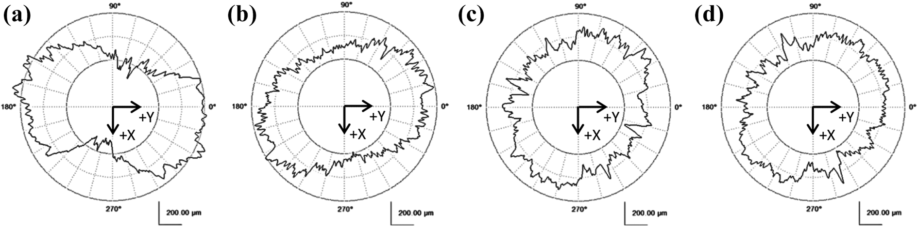
(a) LR Mate 200iC (E31806), (b) LR Mate 200iD (E117096), (c) LR Mate 200iD/7L (E101661), and (d) LR Mate 200iD/7L (E109256).
The type of deformation observed in the recorded circular profiles, in particular, Figure 1(a) and (b), is the characteristic for squareness error and scaling error in systems with Cartesian construction. In the case of the squareness error, the recorded profile has an oval shape or a “peanut” shape with a 45° or 135° inclination (see Figure 2(a)). In machine tools, this error is due to the fact that the two axes performing circular motion are not perpendicular. The second error, the scaling error, is also manifested by the oval shape of the profile, or the shape of the “peanut”; however, the deformation is along the axis at 0° or 90° (see Figure 2(b)). The scaling error is caused by the difference in the size of the motion increment for each axis. 21

Deformation of a circular path due to squareness (a) and scaling (b) error.
In the case of the CNC machine tools with Cartesian construction, the circular motion in a plane parallel to two axes is performed by these two axes which are perpendicular to each other. 22 Conversely, in the case of an industrial robot with series kinematics, the circular motion is the result of the simultaneous movement of several robot joints. 23 Therefore, the total error measured by ballbar is not only a function of errors of individual feed mechanism but it also depends on location in which the measurement is performed. This is caused by differences in the rate of engagements of individual joints in movement along the path of the same shape in different locations. Because of this, the analysis and evaluation of measurements must be approached in a vastly different way compared to methods used with conventional Cartesian systems. 24 Likewise, squareness error and scaling errors, identified on the basis of measurements with Renishaw Ballbar, can be attributed not only to mechanical defects in industrial robots but also to incorrect/inaccurate conversion of Cartesian coordinates, which also attributes to the robot’s overall inaccuracy. Accuracy is defined as a degree of the ability of an industrial robot to reach a programmed point relative to the coordinate system of reference. 17,24 In connection with the completion of the circular path during the measurement with Renishaw Ballbar, precision can also be defined as a degree of the robot’s ability to follow the desired trajectory concerning the coordinate system of reference. The robot’s accuracy is the function of several factors which, according to professional, can be divided into five categories 11,25,26 :
– environment (temperature, humidity),
– parametric factors (e.g. change in kinematic parameters due to manufacturing and assembly errors, the impact of dynamic parameters, friction, and other nonlinearities, including hysteresis and backlashes),
– measurement-related factors (resolution and nonlinearity of joint position sensors),
– calculation factors (such as rounding error), and
– robot application (such as installation errors).
The accuracy of industrial robots can be improved by the process of the so-called calibration. Roth et al. 27,28 divided the robot calibration process into three levels:
– The level 1 calibration (joint level) is based on establishing the right relationship between the actual position of the robot arm and the information from the position sensors in each of its joints. This relationship is created by correctly adjusting the zero positions of the individual robot joints.
– In addition to ensuring the correct relationship between the actual position of the robot arm and the values from the associated sensors, level 2 (kinematic model calibration) also affects the kinematic model of the robot. To refine the robot’s kinematic model, the individual kinematic pairs are considered to be perfectly rigid bodies, without the possibility of its deformation.
– Level 3 (nonkinematic or nongeometric calibration) is the highest calibration level, at which kinematic pairs are no longer considered perfect solid bodies, but factors such as friction and backlash are taken into account. Also, in the case of dynamic robot control, the level 3 calibration is considered to be the application of corrections of the dynamic model of the robot.
The present article deals only with the first-level calibration, related to the setting of a correct position of the individual robot joints. In the case of an industrial robot with serial kinematics, the kinematic pairs are sequenced. For this reason, deviations in the zero joint positions of the robot joints are added together, resulting in incorrect positioning of the TCP. 29 This state is shown in Figure 3, where TCP2 represents the correct position of the robot arm with the correct calibration. On the other hand, TCP1 represents the position of the robot affected by an error from inaccurate or incorrect calibration. Deviations in the zero-position settings of the individual robot joints will result in a different position of the TCP at the end of its arm compared to a robot calibrated properly.

Sample error caused by incorrect positioning of robot joints.
During the creation of the circular path program, the coordinates of the individual points are entered relative to the Cartesian coordinate system. The control system recalculates the defined path to reflect the motion of individual robot joints by the inverse kinematics to move the robot’s TCP along a programmed path. 30 Such calculations are based on a mathematical model in the robot control system, and incorrect calibration does not affect it. Incorrect setting of the zero positions will only take effect when the motion itself is completed. Therefore, it may be assumed that if an error is introduced into the robot calibration, then the path traveled during the Renishaw Ballbar measurement will be deformed and most likely it will take an oval shape or a “peanut” shape. The hypothesis has been confirmed by three experiments described in the following two sections.
Position analysis of robot motion in Creo Parametric 4.0
In the Creo Parametric 4.0 system, a simulation model of the LR Mate 200iC was created using kinematic constraints. 31 The range of motions of the individual joints, as well as their zero positions, were set in the same way as they would be in the case of a real robot. The next step was to define the motion of the TCP to describe a circle with a radius of 100 mm in the XY plane during positional analysis. The center of the circular path is located at the coordinates X = 380; Y = 320; Z = −251, against World Coordinate System (WCS; in the case of Fanuc robots, it is a fixed coordinate system defined by the manufacturer). The result of the positional analysis is the motions of all six robot joints J1–J6, see Figure 4.

Position analysis results showing the motion of robot joints.
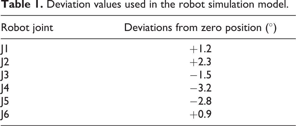
Subsequently, the robot simulation model was modified by introducing an error into the defined zero positions of the robot joints. Deviations from the original, correct zero position, are presented in Table 1. The difference between the robot arm with the correct zero position setting and the use of the deviations mentioned is shown in Figure 3. A positional analysis was done with this modified model of the robot, whereby the motion of the robot was defined by the forward kinematics, that is, by inserting the motion sequences into individual robot joints. For the given motion, the resulting waveforms from the first positional analysis were used, as shown in Figure 4.
Deviation values used in the robot simulation model.
The result of the positional analysis performed on the simulation model of the robot with adjusted zero joint positions (incorrect calibration) is a polar graph showing the deviation from the ideal circle with a radius of 100 mm (see Figure 5). This chart shows the deformation of the circular path, taking the form of a “peanut.” A similar deformation was also seen in the polar graphs when measured with Renishaw Ballbar (see Figure 1(a)).
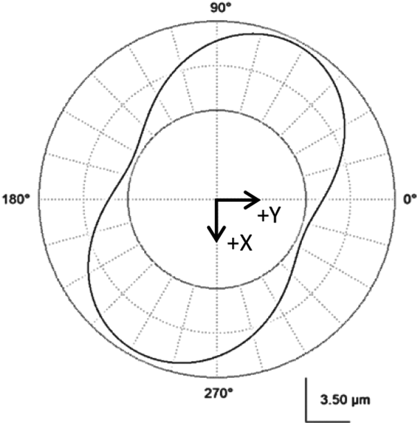
The result of positional analysis in the form of a polar graph.
The positional analysis confirms the possibility of identifying an inaccurate calibration of the robot in the polar graph from the Renishaw Ballbar QC20-W measurement. However, it is important to verify the above conclusions with measurements on a real robot and, thus, to either confirm or correct the results or to refute the existing claims.
Preparation and measurement conditions
Individual measurements were performed on the Fanuc LR Mate 200iC robot, located in the laboratory of the Department of Automation and Production Systems. This robot was chosen not only because of its availability at our Department but also because of the calibration method used so far. Fanuc robots can be calibrated using the following five methods 32,33 :
– Fixture position master,
– Zero position master,
– Quick master,
– Single-axis master, and
– direct setting of calibration data.
During the robot’s normal operation, it is not necessary to carry out or repeat the calibration, as Fanuc robots are already calibrated when produced. However, there are several situations that require recalibration. These include, for example, the event of discharged backup batteries, reinstalling of the control software, interfering with the mechanical part of the robot such as replacing the engine, gearbox, and internal wiring. 32,33 So far, the LR Mate 200iC, on which measurement was performed, has been calibrated several times due to failing of backup batteries. These batteries are necessary to keep values stored in the control system of the robot when it is switched off. In this case, the most important values stored in memory are counts of pulses from the individual encoders in the joints of the robot, corresponding to the current position of the robot arm. In practice, the problem of the backup batteries running flat in the normal operation of the robot rarely occurs. The robot in the Department’s lab spends much more time turned off than it is usual in the industrial environment. Therefore, the memory storing the actual value from the encoders drains the battery much faster.
Until now, the calibration of the robot at the workplace was carried out using the Zero position master method. Fanuc User Manual 33 warns that the accuracy of this method depends only on the visual adjustment of each of the controlled robot joints to the zero position using the reference marks. Furthermore, this method should be used only in exceptional cases. At the same time, it is important to mention that such method possibly does not preserve the accuracy of the robot given by the manufacturer. An adequate method in case of loss of calibration due to discharging of backup batteries is the so-called Quick master. This calibration method uses the original calibration values written in the system variable or in the robot’s documentation. These are the values from the encoders of the individual robot joints, obtained from the initial calibration during the robot’s production.
Based on the above information, it was possible to assume that the LR Mate 200iC robot in the Department’s laboratory was incorrectly or inaccurately calibrated due to repeated use of an inappropriate calibration method. The situation was also consulted with a technician from Fanuc Czech s.r.o. In this case, using the “Quick master” method would not set the zero positions of the robot’s individual joints correctly, but it is likely that the current calibration would be refined. Therefore, two series of measurements were performed, one with the “old” calibration of the robot and the other series of measurements performed after the Quick master calibration. Two measuring methods were used, one utilizes Renishaw Ballbar QC20-W and other Renishaw XL-80 laser interferometer. Based on the results of the positional analysis in Creo Parametric 4.0, it can be assumed that the refinement of the robot calibration would be reflected in the reduction of the circular path deformation when measured with Renishaw Ballbar along the same programmed toolpath. The same analogy can be found even if the robot’s TCP moves along a linear path. For this purpose, straightness measurement with a Renishaw XL-80 laser interferometer was used.
For measurement with the ballbar, the locations of two distinct circular paths were selected, so that their centers were located directly on the longest linear path. At the same time, the requirement for the same X coordinate of the center of both circles was defined, due to the motion happening along one axis (Y) only when the laser interferometer is deployed. The result is a 940-mm-long linear path, passing through both centers of circular paths with a radius of 100 mm, see Figure 6. The measurement conditions, together with the number of repetitions for both measuring devices, are presented in Table 2.
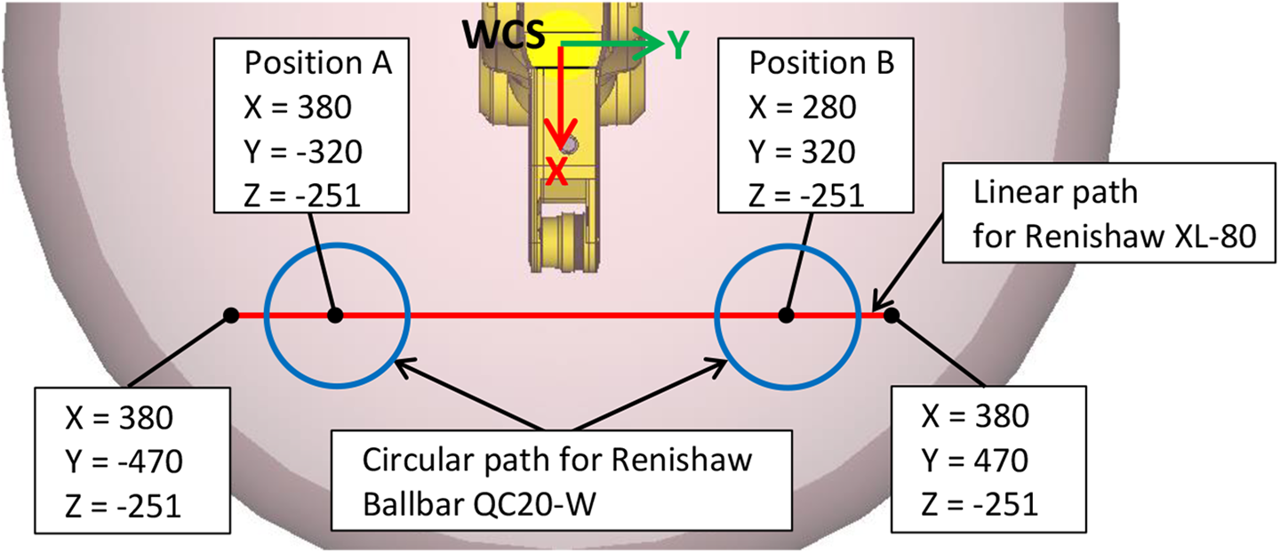
Delimitation of measurement paths in the robot workspace.
Measurement conditions.

Measurement execution and evaluation using the Renishaw Ballbar QC20-W
As mentioned in the previous section, two series of measurements were performed, involving two circular paths (position A and position B) in the XY plane. The first series of measurements were carried out with an inaccurate calibration of the robot. The circular path shapes obtained in both measuring positions are shown in Figure 7, showing a considerable deformation. In addition to the evaluation of measurements based on polar graphs. The average values of the second harmonic component of the profile, representing ovality, were calculated for both measurement directions (see Table 3). The calculation was based on decomposing a circular profile into harmonic components using the fast Fourier transform in Microsoft Excel (using analytical addon NumXL). The amplitude of the first harmonic component of the profile, representing eccentricity, was reset to zero, as it may be considered a measurement error due to the character of measurement.

Circular path profile before robot calibration: (a) measurement at Position A, and (b) measurement at Position B.
Comparison of the average amplitude values of the second harmonic component of the profile.

CCW: measurement upstream control clockwise; CW: measurement clockwise.
After the robot was calibrated using the original calibration values, measurements at both positions were repeated. Based on the results of the positional analysis in Creo Parametric 4.0, a more accurate calibration resulted, manifested as a lesser distortion of the circular path. The correctness of this assumption is supported by polar graphs as shown in Figure 8. Compared to the pre-calibration measurement, the distortion of the circular path was reduced first and foremost, namely in both measured positions. As with the first series of measurements, the mean value of the second harmonic component of the profile was calculated using the fast Fourier transform, see Table 3. By comparing these values of the two measured positions, it can be seen that the average values of the second harmonic component of the profile in the case of a more precisely calibrated robot are almost three to four times smaller than they were before calibration. A graphical comparison of the first 10 harmonic components of the profile before and after the calibration can be seen in Figures 9 and 10. The most noticeable change is observed in the case of the second harmonic component of the profile, representing ovality, which is directly related to the circular path deformation.

Circular path profile after robot calibration: (a) measurement at Position A, and (b) measurement at Position B.

FFT analysis—before calibration.

FFT analysis—after calibration.
It is important to mention in connection with the measurement that the measurement with Renishaw Ballbar was mentioned to be performed in the XY plane (relative to the WCS). However, the robot kinematic structure does not allow to limit real motion to one plane only as it is possible on Cartesian kinematic structures by locking one of the axes. The deviation of the real position from the programmed one is then 3-D. The character of measurement that implements ballbar-type device minimizes the deviation component perpendicular to the plane of measurement. This error can either increase or decrease the measured deviation. A deviation of 1 mm in the Z-axis may affect the measured value by approximately 0.005 mm. Since the impact of such deviation is very small it can be neglected. The influence of the deviation in the perpendicular axis can be further diminished by increasing of measuring radius (effective length of ballbar device).
Execution and evaluation of measurement with Renishaw XL-80 laser interferometer
The analogy to the influence of the robot’s accuracy on the deformation of the real path programmed as an ideal circle can be found in a linear movement when TCP moves along a linear path. Based on the previous results, it can be expected that with an inaccurate robot calibration, the TCP motion programmed along a linear path will be in reality performed as a certain spatial curve. This deformation or deviation from the theoretical linear path will decrease if the robot is calibrated more accurately. Measurements were made with a Renishaw XL-80 laser interferometer to verify this claim.
The Renishaw XL-80 laser interferometer allows several types of measurements to be made. Straightness measurements were used to investigate the effect of calibration on the linear path. This type of measurement is based on the reflector motion along the transmitted laser beam and on the recording of variations in the axis perpendicular to the direction of the motion.
The measurement itself took place along a line formed by 51 points and parallel to the robot’s Y-axis relative to the WCS of the robot. During measurement, the TCP of the robot stopped at each point, and the deviation in the X and Z directions from the ideal line was recorded. Since a bidirectional measurement method was chosen, the X and Z deviations were recorded in both directions of motion. As with Renishaw Ballbar QC20-W, two series of measurements were performed. The first series was carried out with an inaccurate robot calibration, and the same measurement was repeated after the robot calibration by the Quick master method, same as for the measurement with ballbar device.
The graphical representation of straightness measurement results (see Figure 11) shows the actual path of the robot’s TCP during its motion along a linear path. As expected, the linear path is deformed into a curve. By quantifying the straightness value using the so-called Minimum Zone Straight lines (MZS) method in CARTO-Explore (in which the measurement was also recorded), the distance between the lines forming the profile envelope is 652.8 µm for the XY plane (see Figure 11(a)) and 662.6 µm for the YZ plane (see Figure 11(c)). Furthermore, two “bundles” of values can be observed in the graphs, occurring due to the bidirectional measurement selected. One of the bundles represents the values obtained from five repeated motions in a positive direction, and the other represents the values recorded during the backward movement (negative measurement direction). The difference between the two bundles was most probably caused either by the backlash in the robot joints or by insufficient stiffness of the workplace components. However, this claim can only be confirmed by making additional specialized measurements. In addition, based on the graphical evaluation and the density of the curves in both bundles, it is possible to conclude very good repeatability of the tested robot. However, the specific values of repeatability cannot be determined from the measurement performed. For this purpose, another measurement, for example, according to ISO/TR 13309, needs to be done.
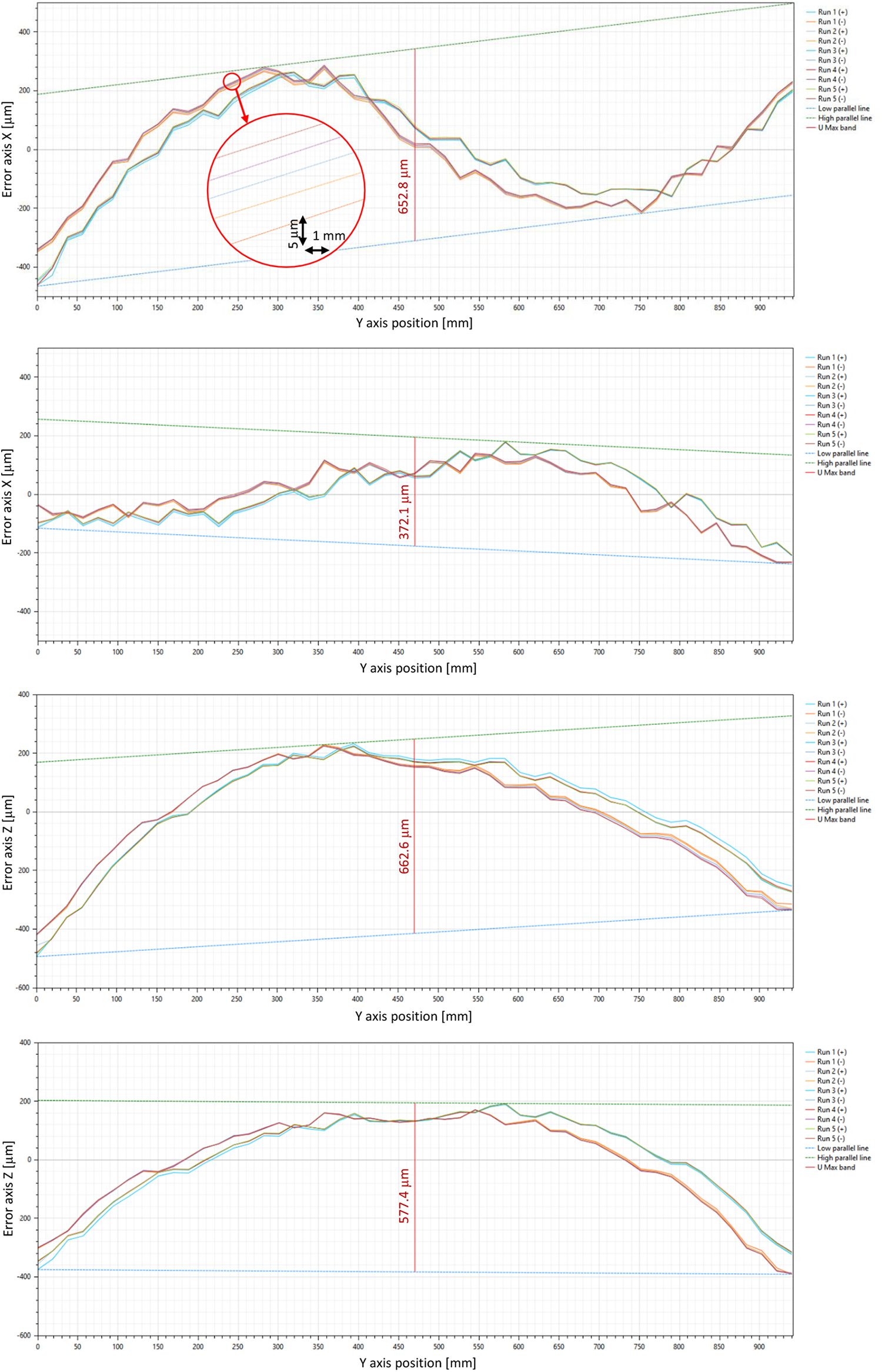
Recorded deviations in straightness measurement in XY and YZ planes, before robot calibration ((a) and (c)) and after robot calibration ((b) and (d)).
After refining the zero positions of the individual robot joints using the Quick master method, the straightness measurement was repeated under the same measurement conditions. The result is the graph in Figure 11(b) and (d). Comparison, the graph before calibration (Figure 11(a) and (b)) shows that, as in the case of a circular path, deformation lessened, that is, the amplitude of the curves has been reduced. The graph also shows two bundles of values belonging separately to the values recorded in the positive and negative measurement directions, as in the case of the pre-calibration measurement. Improved results are also confirmed by the quantified straightness values, which in this case are 372.1 µm for the XY plane and 577.4 µm for the YZ plane. In the XY plane, the straightness error before the calibration is almost double that of the value measured after the calibration.
Result summary
The experiments confirmed the possibility to identify a change in robot accuracy based on the circular path deformation observed in the Renishaw Ballbar QC20-W measurement results. In this case, the accuracy of the robot was influenced by the calibration method used (level 1 calibration). In the first step, the correlation with the circular path deformation was analyzed by positional analysis in Creo Parametric 4.0. After introducing the deviations into the zero-position setting of individual joints in the robot simulation model, the result is a distorted circular path drawn by the TCP. The achieved results were subsequently confirmed by measurements using the LR Mate 200iC robot, which was calibrated to refine the adjustment of the zero positions of its individual joints. This also improved accuracy. Two series of measurements were taken on the robot with the Renishaw Ballbar QC20-W and the Renishaw XL-80 laser interferometer, both done before and also after the calibration. In the case of Renishaw Ballbar measurements, a significant reduction of the circular path deformation was observed on the polar graphs after the calibration was refined. The reduction of the deformation is also confirmed by the value of the second harmonic component of the profile, calculated by the fast Fourier transform. An equally positive effect of the calibration refinement was observed when measuring the straightness of the linear path using a Renishaw XL-80 laser interferometer. Straightness value almost half in the magnitude was measured in the XY plane after the calibration and also the overall amplitude of the recorded curves has decreased.
Conclusion
Renishaw Ballbar, including its proprietary software, is a very effective system that allows fast and simple measurement on machines with Cartesian kinematics. Experience with the equipment at the Department of Automation and Production Systems, as well as results of further research, indicate the potential of this or similar system to be effectively utilized for diagnostics, monitoring, and performance checks of industrial robots. The reliability, simplicity, and speed of measurement are the most basic requirements for methods designed to monitor industrial robots in real-life conditions.
The experiments carried out within the framework of the presented paper were aimed at verifying the established hypothesis of the connection of the accuracy of the industrial robot or that of its calibration, with circular path deformation observed on the polar graphs when measured with a Renishaw Ballbar. The results of the measurements with Renishaw Ballbar, previously carried out at the Department of Automation and Production Systems were an incentive for further work in the field.
The experiments described in the presented paper consisted of two parts. The first was positional analysis with a simulation model of the LR Mate 200iC robot in Creo Parametric 4.0. The second part consisted of practical measurements on the LR Mate 200iC utilizing the Renishaw Ballbar QC20-W and the Renishaw XL-80 laser interferometer. Both positional analysis and measurements confirm the influence of robot accuracy on the magnitude of deformation of the path traveled by TCP compared to its programmed shape. In the case of measurements carried out using the Renishaw Ballbar, the distortion is that of the circular path, in the case of the Renishaw XL-80 laser interferometer, the linear path is distorted. Since the accuracy of the industrial robot can be influenced by the calibration process, an assertion can be made about the ability to identify the accuracy of the calibration process based on the robot’s TCP distortion relative to the previous state. This means that if the robot has been calibrated with a certain degree of accuracy and the subsequent calibration is performed with lower/higher accuracy, this will result in an increase/decrease in TCP path distortion.
The results of the conducted experiments confirm that Renishaw Ballbar can be used to quickly identify the condition of an industrial robot before and after calibration. At the same time, this creates space for the use of this measuring device in the process of monitoring industrial robots, deployed primarily in the field of “precision applications.” In such case, the method of assessing the condition of an industrial robot is based on the assumption that if the periodically repeated measurements are taken at the same location each time and the technical condition of the robot does not change, then the shape of the circular path remains constant. One way to evaluate the measurement is to use a polar graph showing the deviation from the actual circle. Another possibility is to decompose the recorded profile by the fast Fourier transformation and to perform the evaluation, for example, by means of a second harmonic component, representing the ovality of the graph.
Results suggest that the regular measurement of an industrial robot using the Renishaw Ballbar system can be easily implemented into production as a tool for monitoring the changes of its current condition. The measurement itself does not require special skills after the initial setup and can be performed by the robot operator as part of regular tasks. The measurement itself can be performed in the order of minutes per position. Analysis of measurement results can be fully automated using common software such as Microsoft excel. Despite the fact that the currently used software cannot provide information about the source of the errors, experiments proved that these measurements can be a very useful tool capable of identifying emerging errors and thus preventing unexpected downtime. The implementation of these measurements can be beneficial especially for high-precision applications where high repeatability of positioning is critical.
Footnotes
Declaration of conflicting interests
The author(s) declared no potential conflicts of interest with respect to the research, authorship, and/or publication of this article.
Funding
The author(s) disclosed receipt of the following financial support for the research, authorship, and publication of this article: This work was supported by the Slovak Research and Development Agency under the contract No. APVV-16-0283.