
Abstract
The input and output torque testing is crucial for improving the quality of Industry robot reducers. In this study, the TMMISR and TMMOSR for a vertical-type robot reducer detector were designed. The length of measurement chain between the torque transducer and the tested reducer was shorten. The overall stiffness of this instrument has been improved through structural optimization. The characteristics of the two main parts of the torque-measurement errors were also analyzed. A high precision torque calibrator with a standard torque output is used to handle the torque calibration process. An error compensation method based on a backpropagation neural network was adopted for the error compensation process in this study. After error compensation, torque-measurement precision of 0.1% can be achieved by the reducer detector over the full torque measurement scale, and the instrument can be used for both static and dynamic measurements.
Introduction
Industrial robot is a kind of multi joint manipulator or multi degree of freedom machine device, which has certain automaticity and can realize various industrial processing and manufacturing functions relying on its own power and control ability. 1 With rapid industrial development, industrial robots are being widely employed in electronic, logistics, chemical, and other industrial fields. Compared with traditional industrial equipment, industrial robots have many advantages, such as the characteristics of easy to use, high intelligent level, high production efficiency and safety, easy management, and remarkable economic benefits. So that they can operate in high-risk environment.
As a core component of the actuators in industrial robots, 2 the robot reducer directly affects their performance in terms of kinematic accuracy, load capacity, and fatigue life. 3 Therefore, the test of industrial robot reducers is required for developing high-precision industrial robots.4–6 The parameters to be tested mainly include torsional rigidity, transmission error, backlash, lost motion, and transmission efficiency.7–9 Many experts and scholars have done a lot of work on the optimization of the components of the reducer, 10 the optimization of the overall structure of the reducer, 11 and the analysis of the dynamic performance of the reducer.12,13 However, the works above are limited by measurement methods and measurement devices, which seriously hinders the manufacturing quality guarantee of precision reducer. Although some progress have been made in the field of the reducer test equipment.8,14 It cannot meet the development needs of robot precision reducer from the perspective of practical application. In particular, the special measuring equipment mainly needs to be improved from the perspective of instrument structure, torsional stiffness, 15 error analysis, 16 and precision traceability.17,18
Figure 1 depicts a layout commonly employed for the testing of high-precision reducers. This setup can be used for the measurement of multiple parameters. Torque transducers are included in the measurement modules on the input and output sides of the tested reducer, respectively. In addition, the drive and load systems are selected according to the testing requirements. Such instruments typically have a horizontal-type layout. Sensors, driving devices, and other connecting components are supported by cantilevers and fixed on guide rails or a horizontal base in a series of connections.
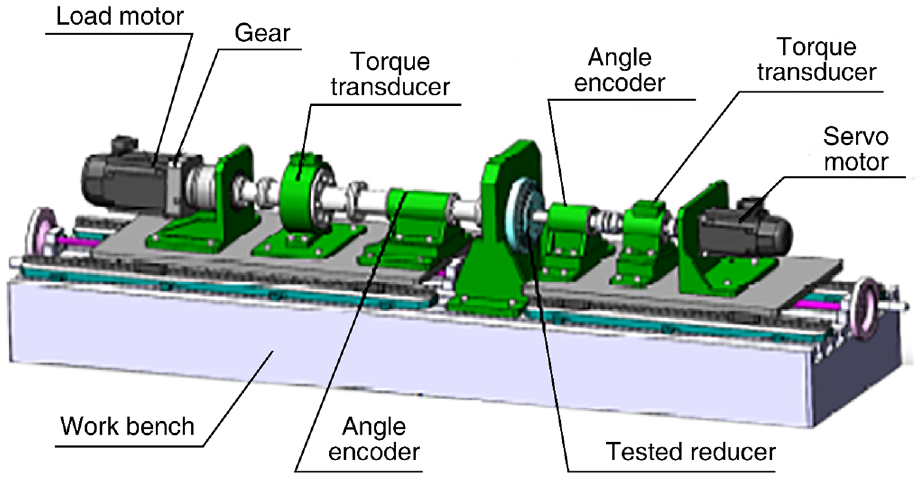
Typical layout of the instrument in reducer testing.
In the above-mentioned horizontal instruments, some parts are installed on the guideway to facilitate the assembly of reducers. However, such a design can adversely affect the overall torsional stiffness of the apparatus. Moreover, it also induces torque-measurement errors due to bending and torsional deflection of the shafts. Further, the uneven frictional force caused by the bending and torsional deflection can lead to torque fluctuations. 19 Thus, the layout of the apparatus ineluctably affects the accuracy of the torque measurement.20,21 Moreover, in practical application, it takes more than an hour to assembly the tested industrial reducer, which brings great difficulties to utilization. 22
In this study, the TMMISR and TMMOSR were developed for a vertical-type measuring instrument. The characteristics of the two main parts of the torque-measurement errors were also analyzed. A high precision torque calibrator with a standard torque output is used to handle the torque calibration process of the torque-measurement system. An error compensation method based on a back-propagation neural network was adopted for the error compensation process in this study. After error compensation, torque-measurement precision of 0.1% can be achieved by the reducer detector over the full torque measurement scale, and the instrument can be used for both static and dynamic measurements.
The unique contribution of this paper is that a decent method to design and calibrate torque measurement system is presented. The unavoidable torque-measurement errors due to shaft bending and torsional deformations were analyzed and compensated based on a back-propagation (BP) neural network. This study not only achieved high-precision torque measurement but also addressed some of the limitations of the existing measuring instrument. High-precision torque measurements are expected to be useful in the comprehensive performance testing of industrial robots.
Sketch of the proposed torque-measurement system
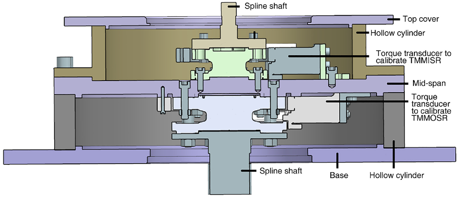
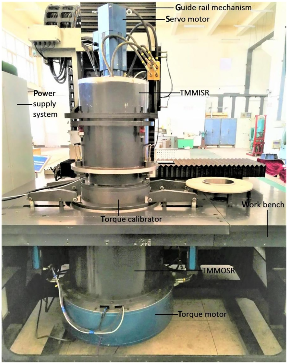
The apparatus, as is shown in Figure 2, is composed of six sub-systems: the power supply system, guide rail mechanism, the torque-measurement module at the input side of the reducer (TMMISR), tested assembly (TA), torque-measurement module at the output side of the reducer (TMMOSR), and the work bench. The power supply system is used to supply power and coordinate the work of the whole apparatus. The guide rail mechanism is used to move the TMMISR so as to install the TA. The TA was used to facilitate the rapid installation of the tested reducers. The work bench supports the TMMISR and TMMOSR. The TMMISR and TMMOSR are designed to measure the input and output torques of the reducer. Each torque-measurement system mainly comprises four modules: motor, torque transducer, test mode conversion part, and connecting parts. The torque-measurement system determines the modes of the test function and motor output based on performance requirements. The connections of the TA to the TMMISR and TMMOSR adopt a unified standard construction.
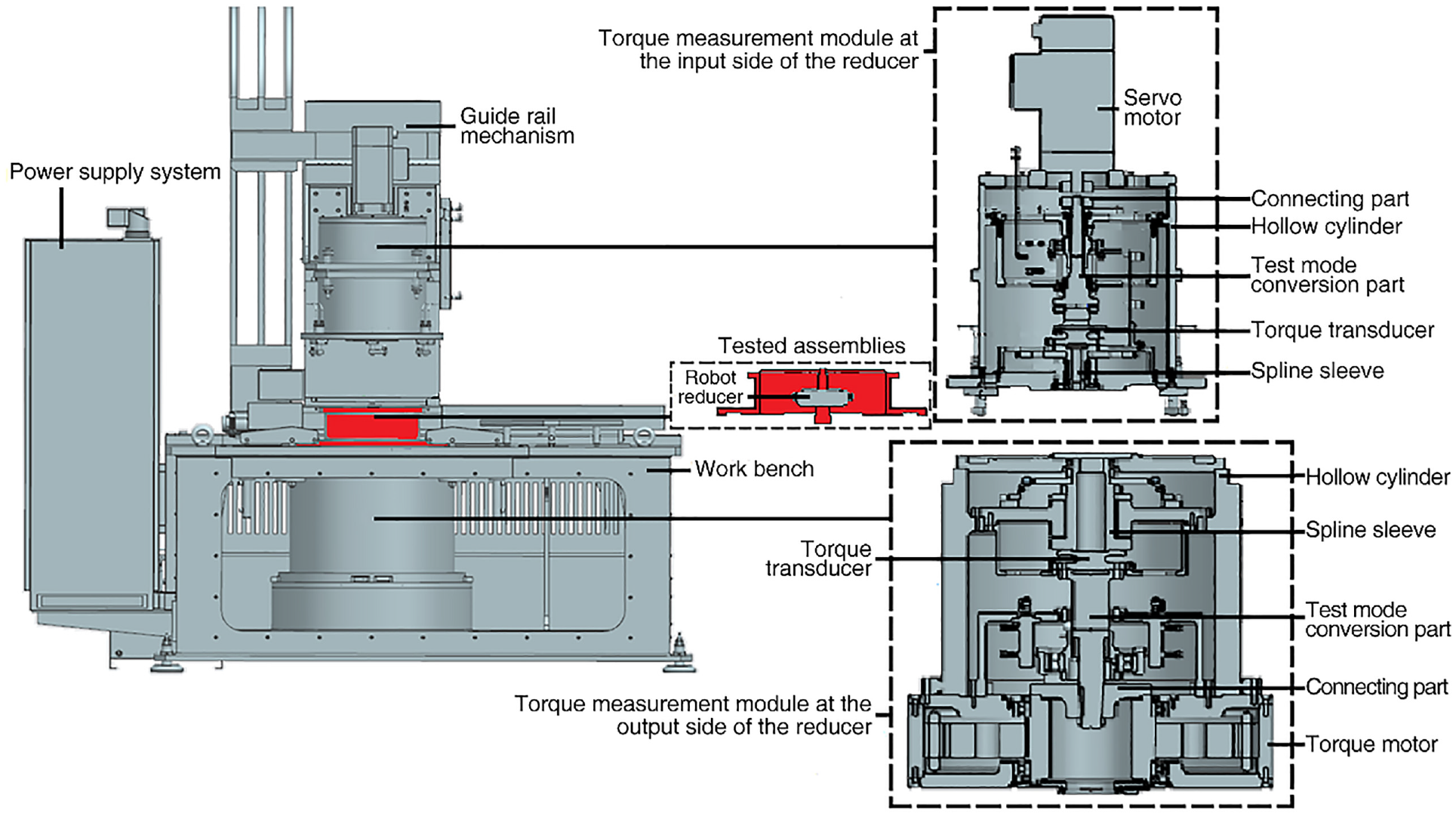
Vertical-type precision robot reducer detector.
During measurements, the TA is placed at the test location. The TMMISR and TMMOSR are located on the input and output sides of the reducer, respectively. The upper and lower flanges of the mechanical connector of TA are pressed by the TMMISR and TMMOSR, respectively. Through the using of TA the installation datum of the reducer is unified with measurement datum of relevant geometric quantities. In this way, the instrument enables to truly reflect the status of the operating reducer in industrial robots.
As mentioned earlier, this study used a vertical-type apparatus, in which functional components are connected in series in the vertical direction. The TMMISR, TMMOSR, and TA are the core components. The external bodies of TMMISR and TMMOSR are cylindrical. The disc supports inside the hollow cylinder ensure that the shafts are centered. The driving and loading parts transmit the torque to the tested reducer through these shafts. The short measurement chain minimizes errors in torque measurements. Moreover, the test mode conversion components allow the input or output shaft of the tested reducer to be under the unconstrained, driven, or locked condition, thereby satisfying the functional requirements of different dynamic and static performance tests. The servo and torque motors provide the torque.
Changes in applied force can result in structural deformation or change the running-status of the apparatus. Subsequently, such changes lead to misalignment errors, which can in turn cause torque-measurement errors. Therefore, the deformation should be limited to a small magnitude as possible to ensure high measurement precision. Thus, it is necessary to consider the impact of component deformation.
In most horizontal systems, the cantilevers in discrete distribution are placed on a horizontal platform to fix each series component and only one end of these supports is fixed. Figure 3 shows how a simplified fixed support withstands torque, which is the fixed support of the horizontal structure test apparatus in Figure 1. It expresses the stiffness characteristic of cantilevers. For comparison, the simulation result presented in Figure 4 show how the hollow cylindrical structure in the instrument described in this paper withstands torque. It can be seen that the structural deformation of this instrument is less than that of the horizontal-type instruments for the same torque. Thus, it is clear that the overall stiffness of this instrument has been improved through structural optimization.
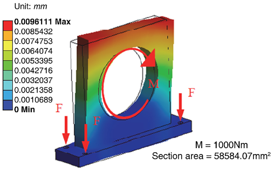
Simulated deformation results of a simplified fixed support.
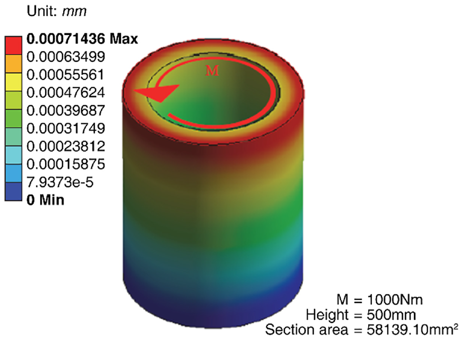
Simulation deformation results of the cylindrical support.
In the above, the deformation of the input side torque measurement system shell and the traditional horizontal structure cantilever support under the same torque is compared by means of finite element analysis. The following is a specific demonstration in theory. According to the theory of equal section straight bar in elasticity, for the horizontal test system of reducer, the torsional angle θt1 within the unit length of rectangular section with side length a and b (a ≥ b) is:
For the torque measurement system described in this paper, the torsional angle θt2 in unit length of a circular section with radius r is:

In these two equations, G is the shear modulus of the material and M is the transmitted torque. Through comparing
Where, a/b∈[1,+∞].
It can be seen from the above analysis that on the premise of equal cross-sectional area,
The coaxiality error of shafting will lead to torque fluctuation, which will affect the accuracy of torque measurement. In the traditional horizontal structure, it is difficult to ensure the coaxiality error of the measured reducer due to the complex structure and the deformation of the cantilever bracket. In addition, the weight difference and coaxiality error of the series components will lead to the uneven friction of the supporting bearing, and the additional torque generated will be included in the measurement results. Especially in the dynamic measurement, because each part is an elastic body, the deformation caused by coaxiality will also result in torsional vibration, which is extremely unfavorable for torque measurement.
Therefore, the torque measurement system of the vertical cylindrical tester adopts the installation reference of the measured reducer as the measurement reference of the instrument. And the gravity direction of each component in the shafting is along the axis direction of the measuring shafting, so as to reduce the influence of gravity on the coaxiality of the shafting. Another important feature of the cylindrical worktable is its simple deformation form, easy description, and accurate compensation. The radial symmetry of the disk support is helpful to ensure the coaxiality of each axis on the measurement shafting.
Analysis of error sources
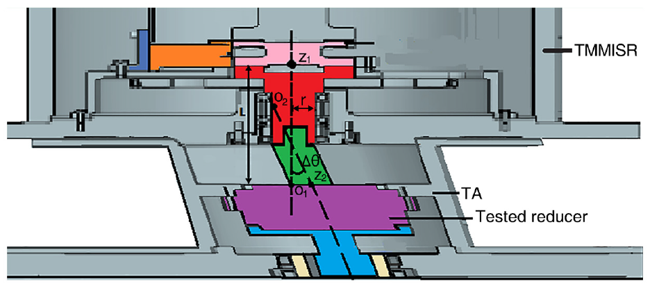
Although the torque transducers are located in close proximity to the input and output sides of the tested target, there is a small gap between each torque transducer and the tested reducer. Figure 5 shows a bearing, a spline coupling (in red) when the TA is placed at the test location. These components are unequal and misaligned which can result in the unbalanced stress distribution at the supports. The unbalanced stress distribution can further cause bending and torsional deformations of the shafts which can consume parts of the transmitted torque. Therefore, the measurement results of the torque-measurement system contain errors caused by the transmission of the torque. The following section presents an analysis of the two main parts of the torque-measurement errors while using the TMMISR as an example.
Components leading to torque measurement errors.
Error due to friction at bearings
Since there a bearing between the torque transducer in TMMISR and the tested reducer, the measurement results of TMMISR would include not only the input torque of the reducer but also the friction torque of bearing. So, the friction torque of bearing must be calculated to make error compensation. Because the deflection of the shaft supported by the bearing is related to the bearing friction torque, the bearing friction torque can be obtained by calculating the deflection angle of the shaft under the transmitted torque. The maximum friction torque of the bearing can be calculated as follows:
Where
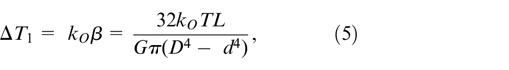
The torque-measurement error caused by the friction of bearings depends quadratically on the torque measured by the torque transducer in the torque-measurement system:
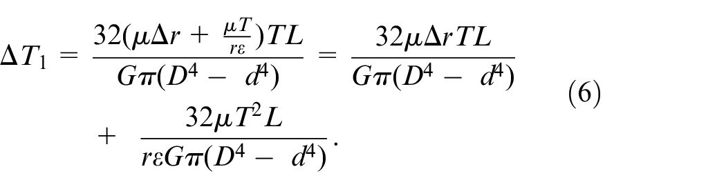
Where
The formula (6) can be used to set the parameters of the BP neural network to make error compensation.
Error caused by misalignment errors
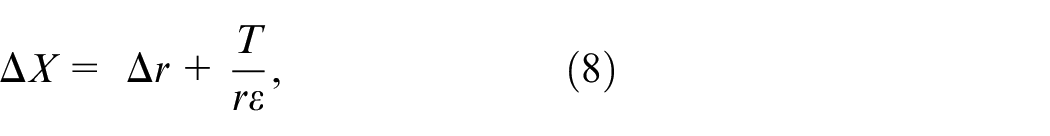
The spline coupling play a vital role in TMMISR. In the perfect operating mode, the axis of torque transducer and the tested industrial robot reducer should be alignment. Actually, this condition does not exist. Manufacturing errors in the components and installation errors often lead to the misalignment of the axis line. The misalignment error consists of parallel and angular displacements. The parallel misaligned error
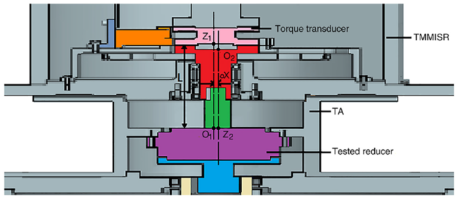
Parallel misalignment error
In Figure 6, O1Z1 represents the axis of TMMISR and O2Z2 represents the axis of the input shaft of the tested reducer.

where
Where
Thus, the error
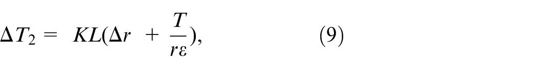
The angular misaligned error
Angular misalignment error
In Figure 7, O1Z1 represents the axis of TMMISR and O2Z2 represents the axis of the input shaft of the tested reducer. When an angular misaligned error exists, the torque measured by TMMISR represents the combined bending moment and torque. Therefore, the torque transferred to the tested reducer is smaller than that measured by TMMISR. The torque-measurement error due to the angular misaligned error is given by
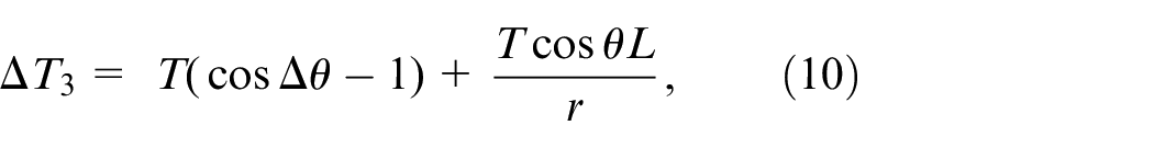
where
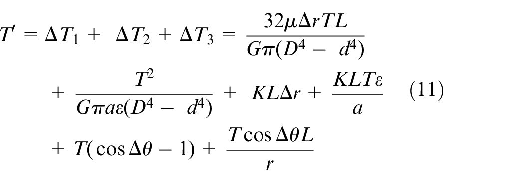
Thus, there is a no-linear relationship between torque-measurement errors and the torque measured by the torque transducer in the torque-measurement system.
Torque calibration and error compensation
The torque measurement system adopts the arrangement of multi-level parts in series in the vertical direction. As one of the series links, torque transducer is the core component of the instrument. And the measured value of the torque transducer is also an important physical quantity representing the performance of the reducer. Therefore, the calibration of torque sensor is very important. The existing calibration methods are direct measurement of the output end of the torque transducer. 23 However, there is a transmission chain between the torque transducer and the tested reducer. As discussed in Section 3, errors, due to the misalignment of the shaft and friction forces from the bearings, were included in the measurement results of the torque transducers. There will be deviation between the actual torque value and the reading value of the torque transducer. Therefore, it is necessary to calibrate the measurement results of the torque measurement system of the instrument.
Torque calibration method
Calibration is a common practice in engineering instrumentation and measurement. The standard measurement results with known accuracy must be used to represent the input and out torque of the tested reducers to compared with the measurement results of TMMISR and TMMOSR to ensure accuracy in the whole measurement range.24,25 This process can get rid of the torque measurement error cause by the transmission of torque in the transmission chain. This comparative method was used to calibrate the torque transducers of the proposed torque-measurement system. After getting rid of the torque-measurement errors cause by the transmission of torque, the final measurement results could be as accurate as possible.
Therefore, a high precision calibrator is used to handle the torque calibration process (Figure 8). The torque calibrator has two high-precision torque output systems, which are used to calibrate TMMISR and TMMOSR, respectively. The external interface of torque calibrator is the same as that of TA, and can be connected with the instrument according to the standard interface. During the calibration, the torque calibrator is placed on the test position instead of the TA. The upper and lower flange of the torque calibrator are respectively connected with TMMISR and TMMOSR, and are compressed by hydraulic mechanism. Then TMMISR and TMMOSR are calibrated respectively. The torque calibrator enables to calibrate torque under the status of the operating reducer in industrial robots, since that the using of TA enables to make the tested reducer under the status of the operating reducer in industrial robots and the structure of torque calibrator is the same as that of TA.
Design of the torque calibrator for the measuring instrument.
The calibrator used in this study was calibrated by the National Institute of Metrology (NIM) of China. Since the NIM can only calibrate 50 points of the average distribution of torque calibrator in the full range, when using torque calibrator to calibrate the torque measurement system in the instrument, the standard torque value of the two torque output systems of torque calibrator is discrete and 50 data are distributed in the whole range.
When the motor is loaded with torque, the readings of the torque measurement system and torque calibrator are recorded at the same time. The real-time calibration data of torque measurement can be obtained by comparing the torque transducer reading on the calibrator with the reading of the corresponding torque transducer of the torque measurement system.
Error compensation method
Because the measuring range of torque measuring system is wide, it is difficult to find continuous standard torque as the calibration standard in the calibration process. If the torque load fails to be calibrated on full range, but only on some loading points, the measurement accuracy of the non calibration point cannot be guaranteed. Besides, torque-measurement errors are complicated to calculate or measure. Moreover, the relationship between them and the measurement results of the torque-measuring system is nonlinear. Thus, compensation for torque measurement errors is necessary in high-precision measurements. In this regard, the data over the entire range must be fitted according to the 50 groups of dispersed standard torque considered.
As is described in the third section, a quadratic relationship exists between the measurement results of the torque-measuring system and the torque-measurement errors. Therefore, the compensation of torque-measurement errors can achieved by using polynomial fitting. However, its accuracy is not sufficient due to the limited number of sampling points. Because only 50 groups of dispersed standard torque were considered, the results of compensation would be unsatisfactory. On the contrary, a BP neural network does not concentrate on the features of error. Thus, it was put to use for the process of error compensation in this study.
Any nonlinear relationship between the input and the output can be accurately revealed using a three-layer BP neural network. The relationship between the measurement results of the torque-measurement system and the torque-measurement errors can be revealed effectively. The BP neural network used for torque error compensation corresponds to a three-layer one-way propagation network, as shown in Figure 9. It consists of an input layer, an output layer, and a hidden layer. There is one node in the input layer of the network (expressed as
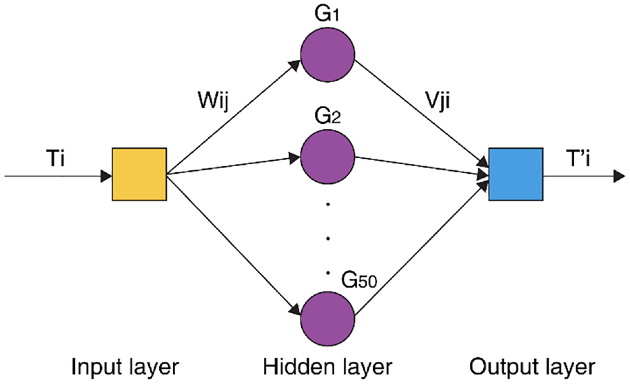
Torque error compensation model.
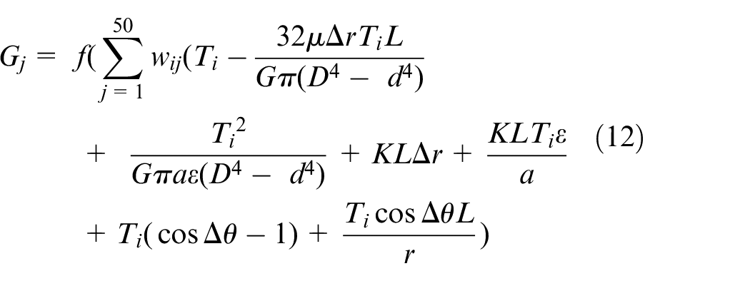
The measurement results of the torque-measurement system and the corresponding standard torque values are used as learning samples for training. The output of the hidden layer is given by
The model of the output layer node is given by
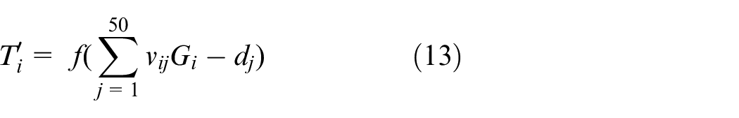
In the formulas above,

where
The steps to train the BP neural network and compensate the errors are as follows: (1) First, replace the adapter and reducer with the torque calibrator. (2) Get the 50 groups of dispersed the measurement result of the torque transducer in the torque-measurement system and the standard torque value of the torque calibrator. (3) Then, enter the hidden layer function into the BP neural network according to equation (11). (4) Next, take the measurement result of the torque transducer in the torque-measurement system as the input of the neural network and take the standard torque values as the output of the neural network. (5) Train the BP neural network by adjusting the weights and thresholds again and again to make the total error less than the setted value. (6) After training the BP neural network, the input and output torque of the reducer can thus be obtained by using the random measuring result of the torque-measurement system as the input of the BP neural network. And the error can reach less than 0.1% in the full range.
Experiment and results
Hardware and software
The equipment used in the torque measurement instrument includes torque transducers (T40B, HBM, Darmstadt, Germany), a PXIe acquisition system (PXIe-7961, National Instruments, Austin, USA), a servo motor (SMS15-42P2C, Modrol Electric Co. Ltd., Guangdong, China), and a torque motor (MDD310, Modrol Electric Co. Ltd.).
The measurement range of the torque transducer in the TMMISR is 0–50 Nm, and its measurement accuracy is 0.1% in full scale. The measurement range of the torque transducer in the TMMOSR is 0–2000 Nm, and its measurement accuracy is also 0.1% in full scale. The PXIe acquisition system was used to collect the frequency signals of the two torque transducers synchronously. The accuracy of torque signal acquisition of the PXIe acquisition system is 0.1% in full scale. The servo motor and torque motors are precision instrument level motors. The loading accuracy of the servo motor and torque motor is 0.1% in full scale. The physical details of the parameters of the hardware are presented in Table 1.
Physical details of the parameters of the hardware.
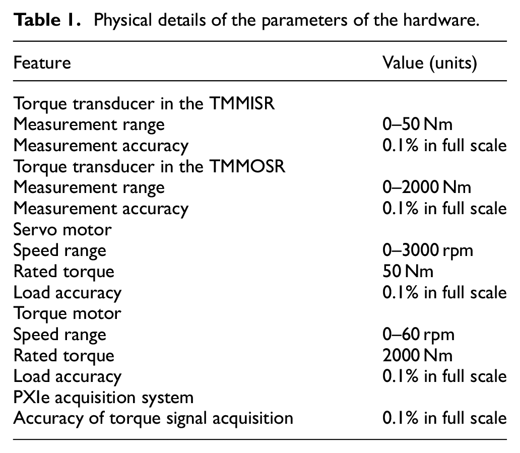
Since the torque transducers in the TMMISR and TMMOSR were calibrated by the calibrator which was calibrated by the National Institute of Metrology (NIM) of China, the physical parameters of the torque transducers will not change. The physical parameters that will change are the loading accuracy of the servo motor and torque motor. The changing of the loading accuracy can lead to random error of the torque calibration results. Since the load is increased 2% of the full range every 500 ms from 0 Nm to the full range. The proposed torque calibration method use the DC component of the measurement results of the torque transducers at any loading point to deal with the changing of the loading accuracy.
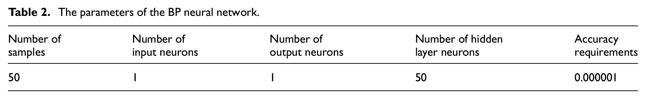
The BP neural network was programmed using LabVIEW. Man-machine interfaces for data acquisition, parameter settings, state display, and system operation control were developed. The acquisition system was configured using the parameter setting interface. The status display interface was used to display the operation of the experimental device and provide timely information in case of a fault. The operating control interface of the system allows loading of the experiment, torque signal acquisition, BP neural network training, error compensation, a display of the results, and access to other interfaces. The parameters of the BP neural network is shown in Table 2.
The parameters of the BP neural network.
Testing and verification of the proposed measuring method
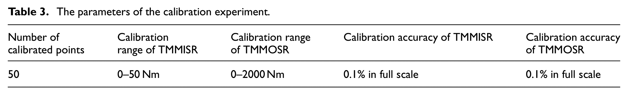
The torque-measurement system and the torque calibrator described earlier in the previous sections were used in the testing and verification of the proposed method. As is shown in Figure 10, in the calibration experiment, the torque calibrator was installed on the test position and the steps outlined in the torque calibration method discussed in the fourth Section were followed. Adjust the output of torque transducers in torque measurement system to 0 N m when it is not loaded. The motors in the torque-measurement system applied torque step-by-step, clockwise, or counterclockwise. We recorded the measurement results of the torque-measurement system and the standard torque values of the torque calibrator. Then the BP neural network is trained according to the standard torque value and the torque measurement results of the torque measurement system, and the complete torque error curve is obtained. The parameters of the calibration experiment is shown in Table 3. The error curve of the TMMISR and TMMOSR is shown in Figures 11 and 12, respectively.
Experimental calibration of the torque transducers in the measurement system.
The parameters of the calibration experiment.
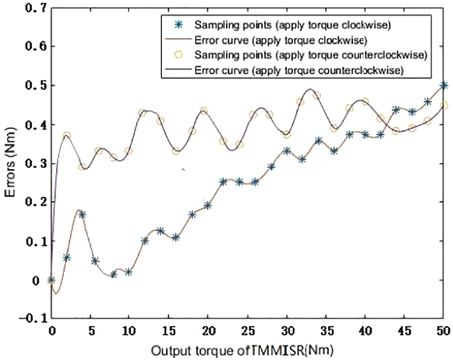
Error fitting curve of the output torque of the TMMISR.
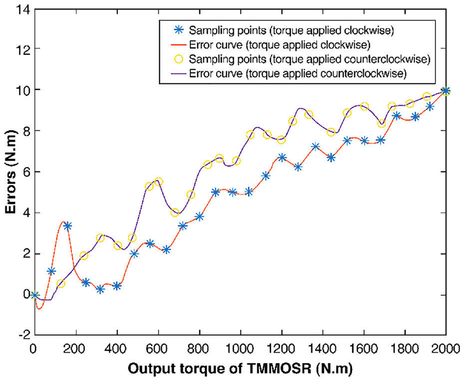
Error fitting curve of the output torque of the TMMOSR.
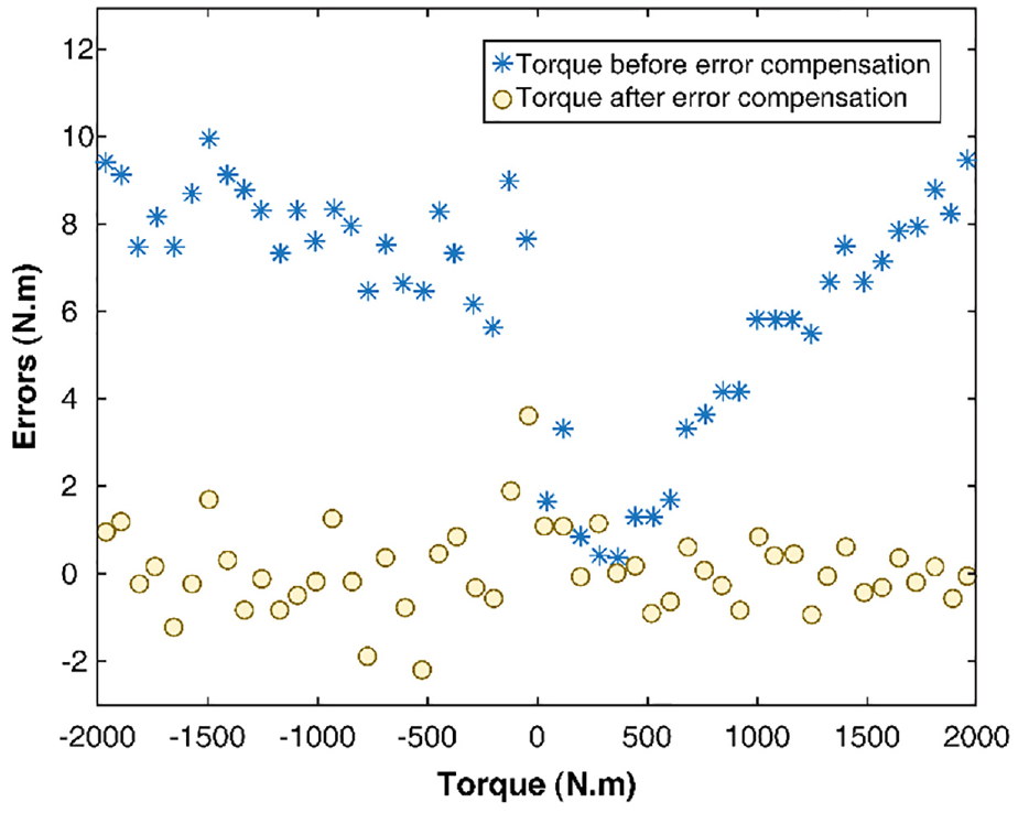
The higher precision measuring device certified by NIM, which accuracy reached 0.002% in the full measurement range, was used to verify the compensation results of torque-measurement errors in the torque-measurement system. The measuring range of TMMISR and TMMOSR were ±50 and ±2000 N m, respectively. The positive and negative signals signify that the torque directions are clockwise and counter-clockwise, respectively. The comparison of the measurement results of TMMISR and TMMOSR before and after error compensation is presented in Figures 13 and 14, respectively. As a comparison, the measurement results TMMOSR after error compensation using polynomial fitting is presented in Figure 15.
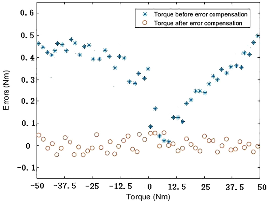
Errors for the TMMISR before and after compensation using the BP neural network.

Errors for the TMMOSR before and after compensation using the BP neural network.
Errors for the TMMOSR before and after compensation using polynomial fitting.
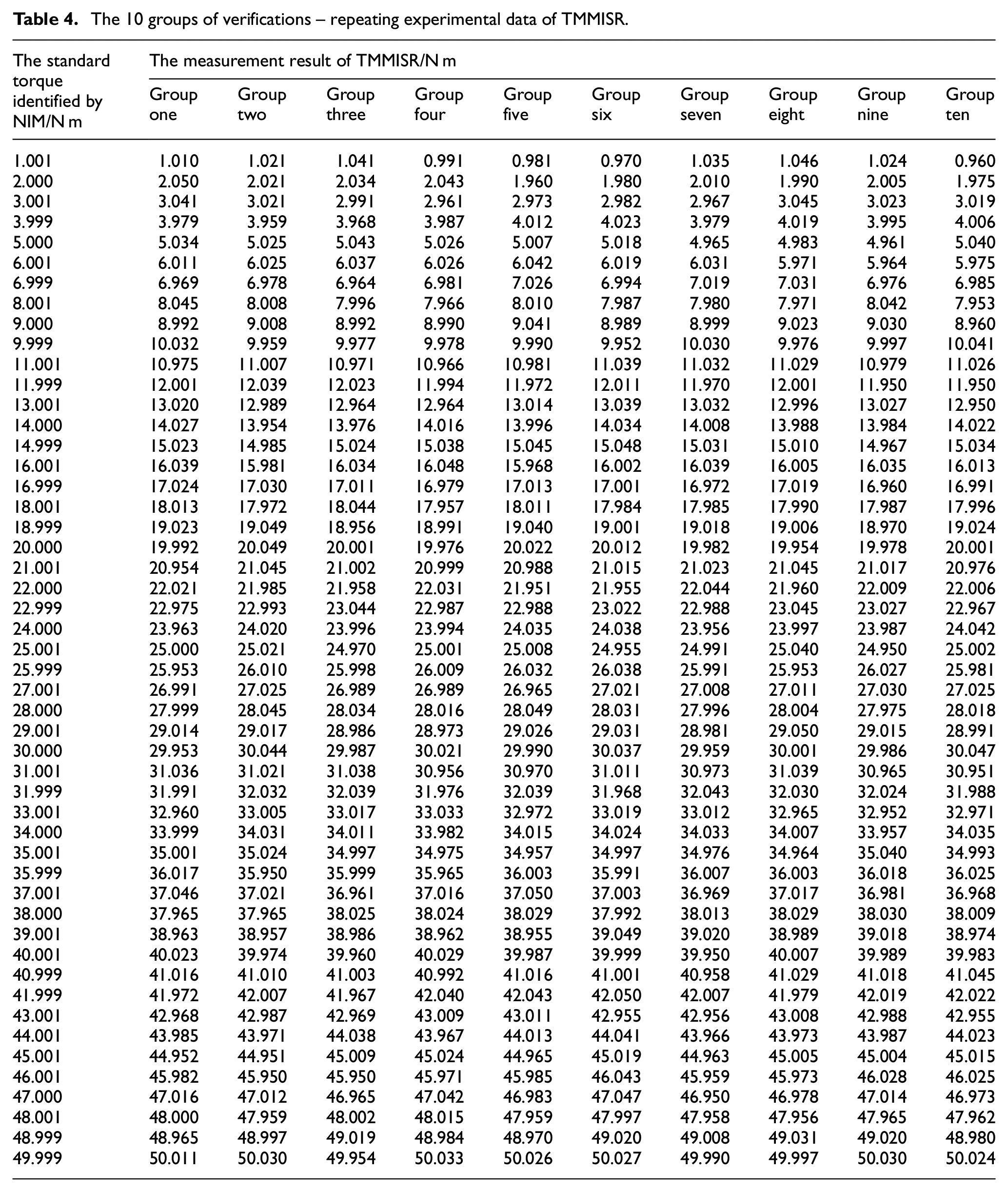
The experiment results indicate that after error compensation using the BP neural network the torque-measurement error is less than 1.8 N m, which is 0.09% of the entire measurement range. However, after error compensation using polynomial fitting the maximum torque-measurement error can reach 4 N m. So, the BP neural network is better for error compensation than polynomial fitting. Through 10 groups of verifications – repeating the experiments, it can be obtained that the torque-measurement accuracy of the instrument reached 0.1% in full scale. The 10 groups of experimental data of TMMISR are listed in Table 4. The 10 groups of experimental data of TMMOSR are listed in Table 5. In the horizontal-type instruments depicted in Section 1, although the torque transducer is calibrated by a system output with high measurement accuracy the torque-measurement accuracy is only about 0.5% in full scale. 9 That is because the torque transducer in the horizontal-type instruments is not calibrated in the measurement chain and the errors, due to the misalignment of the shaft and friction forces from the bearings, are not compensated. The torque-measurement method described in this paper is thus superior to those proposed in previous studies.
The 10 groups of verifications – repeating experimental data of TMMISR.
The 10 groups of verifications – repeating experimental data of TMMOSR.
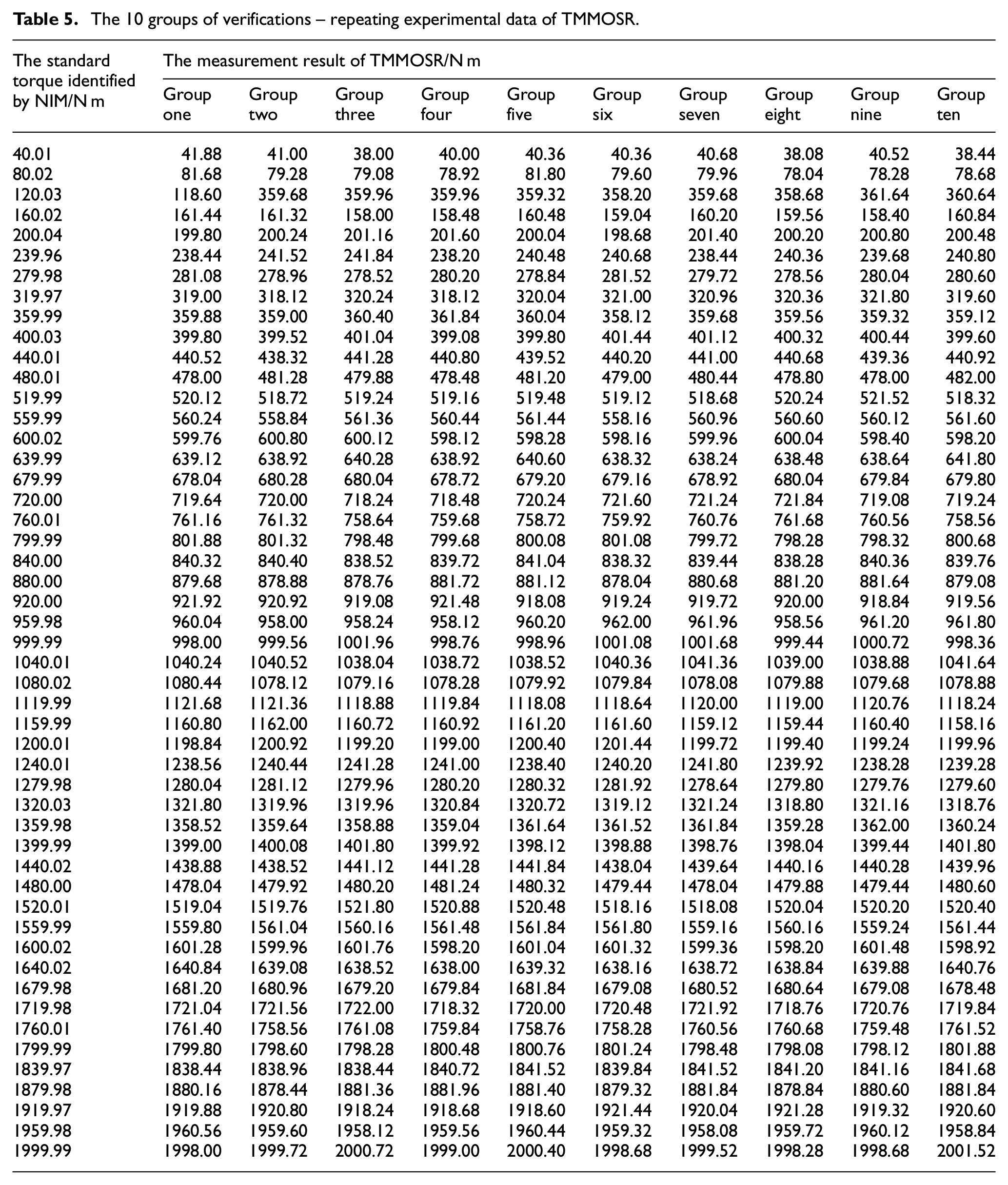
It can be seen from the two tables above that the torque measurement error of TMMISR and TMMOSR, although randomly, is less than 0.1% in full scale. And the repeatability error of TMMISR and TMMOSR is less than 0.1% of the entire measurement range.
In order to show the proposed method works, an experiment of testing the no-load friction torque of a standard reducer, with known friction parameters, under different rotation speeds have been done, as is shown in Figure 16.
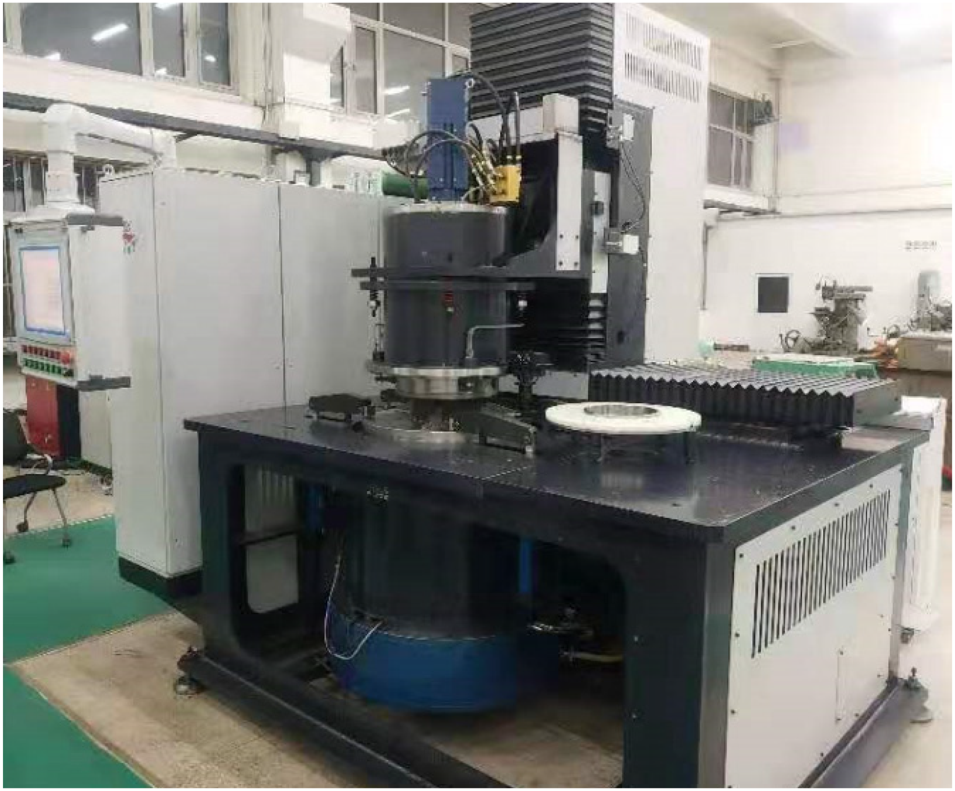
Experiment of testing the no-load friction torque of a standard reducer.
In the experiment, TA is placed on the test position. TA is connected with TMMISR and disconnected with TMMOSR. Motor of TMMISR is used to increase the rotation speed step-by-step from 0 to 1200 rpm, that is 15 rpm for the output side. The experiment is carried out under no load. In the process, the calibrated torque transducer in the TMMISR test the no-load friction torque of the standard reducer. Since the friction parameters of the standard reducer is known and the no-load friction torque of the standard reducer under different rotation speeds have been calibrated, the measurement accuracy of the calibrated torque transducer in the TMMISR can be obtained through three groups of independent repeated experiments. The results of the experiment of testing the no-load friction torque of a standard reducer is shown in Table 6.
The test results of the no-load friction torque of a standard reducer.
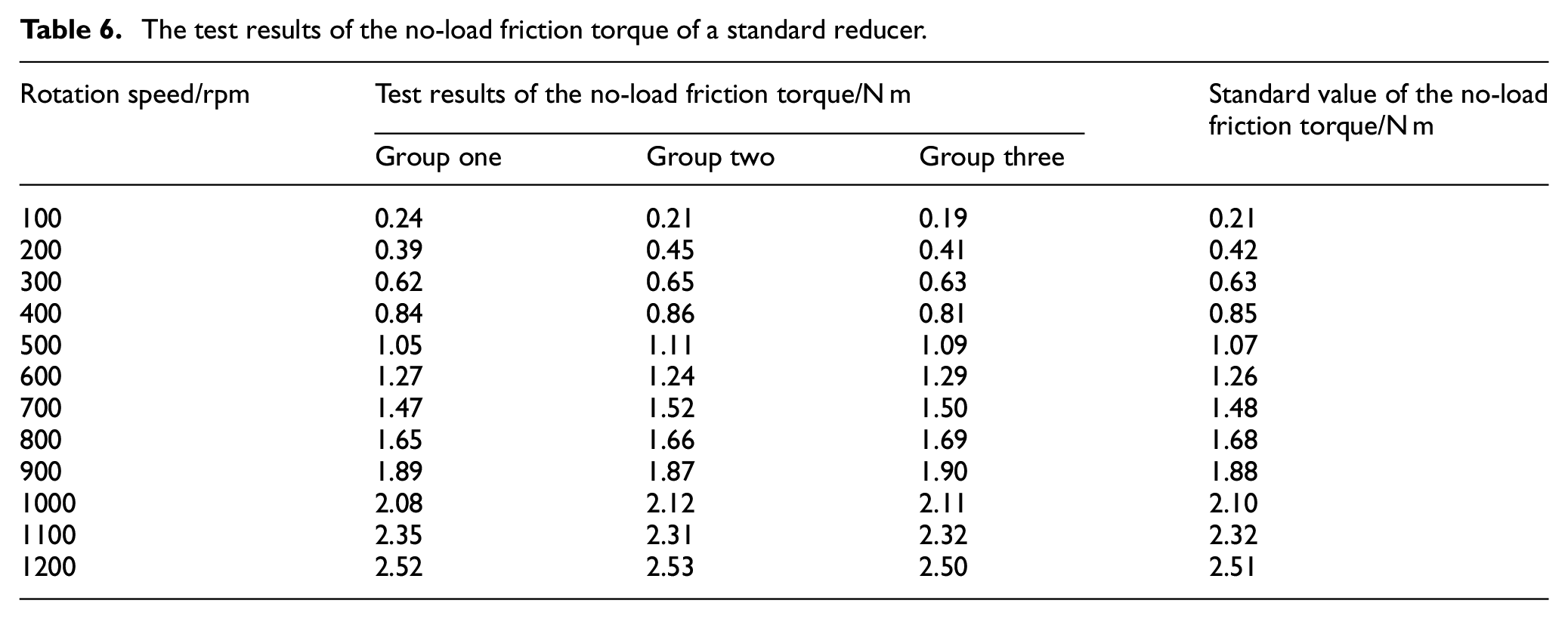
It can be seen from Table 6 that the torque measurement error of the calibrated torque transducer, although randomly, is less than 0.1% in full scale. And the repeatability error of the calibrated torque transducer is less than 0.1% of the entire measurement range.
Conclusion
In this paper, the TMMISR and TMMOSR were developed for a vertical-type measuring instrument. The characteristics of the two main parts of the torque-measurement errors were also analyzed. A high precision torque calibrator with a standard torque output is used to handle the torque calibration process of the torque-measurement system. An error compensation method based on a BP neural network was adopted for the error compensation process in this study. After error compensation, torque-measurement precision of 0.1% can be achieved by the reducer detector over the full torque measurement scale, and the instrument can be used for both static and dynamic measurements.
The unique contribution of this paper is that a decent method to design and calibrate torque measurement system is presented. The unavoidable torque-measurement errors due to shaft bending and torsional deformations were analyzed and compensated based on a BP neural network. This study not only achieved high-precision torque measurement but also addressed some of the limitations of the existing measuring instrument. High-precision torque measurements are expected to be useful in the comprehensive performance testing of industrial robots.
This study did not involve extensive dynamic calibration. The torque transducers of TMMISR and TMMOSR are currently calibrated under static conditions. However, the instrument is not limited to static measurement but is also applicable to dynamic measurement. Besides, the torque measurement error varies with speed, bearing lubrication, and temperature in the dynamic tests. So, more experiments and models are required in the future to improve the accuracy of dynamic torque measurement. The causes of error of dynamic torque measurement must be identified and the measurement accuracy of the instrument under dynamic condition need to be improved further.
Footnotes
Appendix
Author contributions
Conceptualization: Wancheng Yu, Zhen Yu; Data curation: Zhen Yu, Yuan Zhang, Xiaomin Liu; Formal analysis: Wancheng Yu, Yuan Zhang; Methodology: Wancheng Yu, Zhen Yu; Validation: Wancheng Yu, Zhen Yu, Yuan Zhang, Xiaomin Liu; Writing – original draft: Zhen Yu; Writing – review & editing: WanchengYu, Zhen Yu, Xiaomin Liu.
Declaration of conflicting interests
The author(s) declared no potential conflicts of interest with respect to the research, authorship, and/or publication of this article.
Funding
The author(s) disclosed receipt of the following financial support for the research, authorship, and/or publication of this article: This research was financially supported by the National Key Research and Development Program of China (NKRDPC) (No: 2017YFF0108100).
Code availability
No code is available.