
Abstract
During the movement of a robot on the outside of a pipe, it either exhibits linear or rotating motion along the axis of the pipe. In this process, not only is there conversion between kinetic energy, potential energy, resistance power consumption, and external work, but there are also complex mechanical relationships that occur. To solve the dynamic problems of the out-pipe climbing robot in space, the axis and diameter of the pipe were simplified to the virtual joints of a robot with zero mass, and the virtual dynamic model of the robot in space has been established. According to the vector of the arbitrary position of a particle robot around an inclined pipe, combined with the improved Lagrange–Newton–Euler method, the system’s dynamic equation that includes friction has been established, and the required driving force for an arbitrary position of the robot in the process of circling an inclined pipe has been obtained.
Introduction
In recent years, as a branch of robotics research, pipe climbing robots have flourished to meet the needs of different working environments. 1 In the process of a robot winding itself around a pipe, not only is there energy being converted between the different forms, which include kinetic energy and potential energy, but there are also the multivariate dynamics that possess complex relationships. For example, gravity always acts in the same direction; however, the friction changes due to the speed, direction, or rotating angel of the robot on the pipe; the centripetal force changes with the direction or magnitude of the speed, and the damping force of the air also changes with the speed of the robot. Therefore, it is necessary to study the balance of the dynamics of the arbitrary position of a particle robot around an inclined pipe.
There are several types of climbing robots; some robots climb inside a pipe, 2 –5 while others climb outside of a pipe. 6 –8 In terms of robot dynamics, 9 many scholars have conducted dynamic analyses of robots climbing vertical pipes, 10 and other researchers have also performed simple mechanical analysis of the friction that occurs during the climbing process. 11 Critical static analyses of arbitrary angles around the axis on an inclined pipe have also been performed in the literature 12 ; Bezak et al. have described inverse dynamics model. 13 Bozek et al. have described the calculations of complex curves trajectory of the robot movement. 14 Pivarčiová et al. have described a method proposed to analyze control and correction options of mobile robot trajectory by an inertial navigation system. 15 However, dynamic analyses of arbitrary angles around the axis of an inclined pipe have rarely been carried out.
It is very difficult to investigate the dynamics of robots separately from those of the pipeline. In order to solve the dynamic problems of pipeline robots, the axis and diameter of the pipe can be simplified to the virtual joints of a robot that has zero mass, and the dynamic model of the robot can then be established. According to the vector of the arbitrary position of a particle robot around an inclined pipe and based on the Lagrangian dynamics, first the system calculation is performed and then in combination with the Newton–Euler method, the effect of friction is taken into consideration in the system, and the dynamic equation can be established, and finally the driving force of the arbitrary position can be obtained. Through this method, the space dynamics problems of a pipe climbing robot can be solved.
Establishing the pipeline’s coordinate system
To express the relationship of the position of a pipe climbing robot in space, the pipe’s coordinate system has been established.
13
As shown in Figure 1, for the convenience of the research on this problem, the axis of the pipe is denoted by y
1 in the plane yoz; the intersection of the axes y
1 and z is o
1, and the angle between y
1 and y axes is

Coordinate system of the pipe.
Establishing the virtual dynamics model of a pipe climbing robot
It is difficult to investigate the dynamics of a robot in the pipeline space alone; therefore, a virtual dynamic model for this purpose was established (Figure 2) in order to solve this problem. In this model, the movement of the robot along the axis of the pipe has been simplified as a prism; meanwhile, the force between the robot and the pipe has been simplified to the force between the prism pairs and finally decomposed to each drive wheel. The rotation of the robot around the pipe can be simplified to the rotation around the axis of the pipe, and the force of the pipe can be simplified to the force of the rotating joint and finally decomposed to each driving wheel. Therefore, the movement of the robot on the pipeline has been simplified to a virtual robot model based on the prism and the rotary joint of the pipeline system. The y
1 axis of the inclined pipe has been simplified to the axis of the prism pair, and O
1 is the coordinate center of the prism pair. The radius
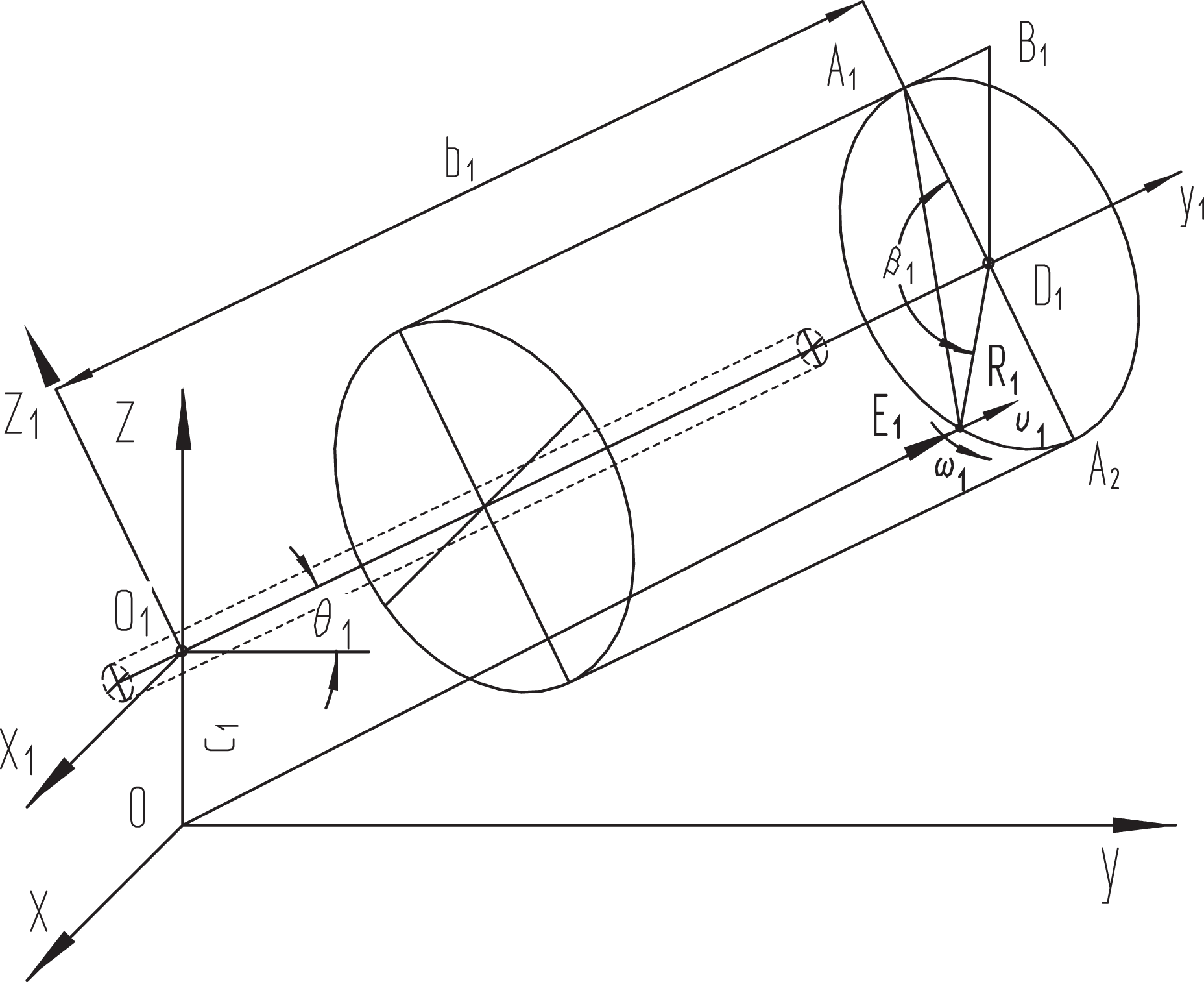
Dynamics model of the particle robot in the pipeline space.
Theoretical basis and improvement in the dynamics model
To analyze the dynamic mathematical model of the operation of the robot, the following two theories were applied:
The basic theory of dynamics is the Newton–Euler dynamic equilibrium method. Its general form can be written as

where K, P, D, and W represent the kinetic energy, potential energy, energy consumed, and work done by the external forces of the object, respectively; qi
represents the coordinates of the kinetic energy and the potential energy; and
Lagrangian mechanics, in particular, the second-order Lagrangian equation.
16
The Lagrange function is defined as the difference between the kinetic energy and the potential energy of the system, that is

where L is the Lagrange function, K is the kinetic energy of the system, and P is the potential energy of the system. K and P can be represented by any convenient coordinate system.
The system dynamics equation, that is, the Lagrange equation can be written as follows

where Fi is the force or moment acting on the ith coordinate. Fi is determined from the linear coordinate or the angular coordinate qi . These forces, moments, and coordinates are called generalized forces, generalized moments, and generalized coordinates, respectively. The other parameters are the same as in equation (1).
There are both advantages and disadvantages to the two methods for the dynamic analysis of a pipe climbing robot. The first method is capable of taking friction into consideration in the system; however, due to the change of the motion state, the process is very complicated and troublesome. The second method can directly obtain the result without taking the internal force into consideration but does not incorporate friction.
To obtain the relationship between the driving force and the friction, the Newton–Euler method must be transformed, that is
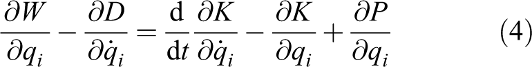
The right side of equation (4) takes the form of the Lagrange equation. The Lagrange–Newton–Euler method can be obtained by combining equations (3) and (4)

The purpose of studying equation (5) is to firstly calculate the resultant force Fi
using the Lagrange algorithm, and then calculate the required driving force (
The process of solving the classical Lagrange function is divided into five steps as follows: Calculate the velocity of any point on the joint. Calculate the kinetic energy of each connecting rod and the total kinetic energy of the robot. Calculate the potential energy of each connecting rod and the total potential energy of the robot. Establish the Lagrange function of the robot system. Derive the Lagrange function to obtain the dynamic equation.
The five steps above are only used to obtain the generalized resultant force or the resultant moment Fi on the left side of equation (5). The relationship between the driving force and the friction force can be calculated by further combining this with equation (4).
Dynamic analysis of the pipe climbing robot
According to the hypothetical step-by-step method in the literature, 13 the position vector of the robot to the origin coordinate O of the base coordinate system, when a pipe climbing robot climbs on a pipeline, can be obtained from the following equation
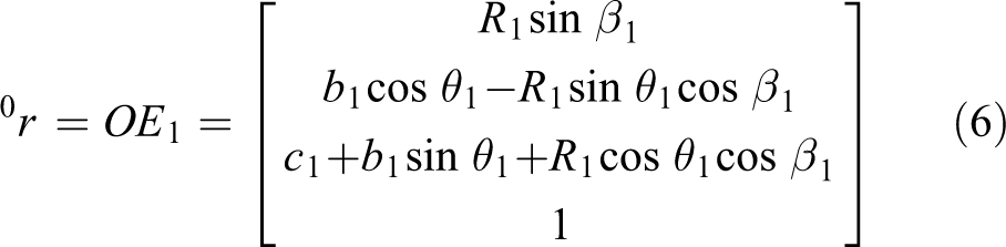
where
According to equation (6), the following can be obtained

where
According to equation (7), the square of the velocity of the robot is

where
According to equation (7), the acceleration a 0 of the particle robot is

where
Therefore, the kinetic energy of the particle robot can be obtained from the following equation

The total kinetic energy of all transmission devices can be obtained from

where i is the number of rotating parts.
The total kinetic energy of the robot’s system (including the transmission device) can be written as

where
According to equation (12), the following can be obtained

The partial derivative of the generalized coordinate

The partial derivative of time t in equation (14) can be written as

In this system, the basic coordinate system is the ground; therefore, the gravity field vector can be written as

Hence, the potential energy of particle robot can be written as
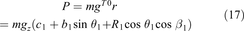
In equation (17), the term (

The Lagrange function (2) obtained from equations (12) and (17) can be written as

For the generalized position coordinates in equation (19), by combining equation (5), the force can be obtained from the partial derivative as follows

According to equation (5), the generalized resistance can be written as

where c 2 is the speed-dependent resistance coefficient, and F 1 is the friction between the robot and the pipe (N).
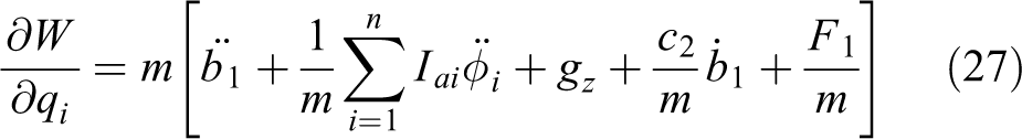
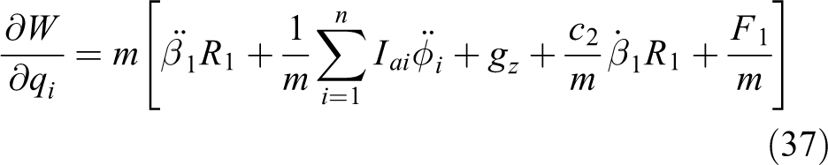
Substitute equations (12), (15), (18), (20), and (21) into equation (5). The driving force of the particle robot at an arbitrary position can be obtained from equation (5)

where
Acceleration of the robot particle can be calculated when the driving force

where a 1 denotes the acceleration of the robot particle in m/s2.
Discussion
Analysis of equation (22) indicates that there exist both linear and rotational motion parameters in the process. On the other hand, combination of different states produces different results. Therefore, they are regarded as subitems for further investigating the dynamics of the robot. When
Regardless of the robot particle motion along the inclined pipe axis, it always includes the starting phase acceleration, uniform motion phase, and the braking phase deceleration. It should be indicated that these stages exist for all robot particle motions, including the linear motion, rotating motion around the pipe axis, and the spiral composite motion. Therefore, in order to study the dynamic characteristics of the pipe climbing robot, it is necessary to investigate the dynamics of different motion states.
Dynamics of the upward motion along the inclined pipe axis
In this process, related parameters to the rotation (i.e.
(1) Dynamics of the upward accelerating start-up along the inclined pipe
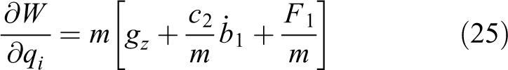
During the upward accelerating start-up along the inclined pipe, the driving force

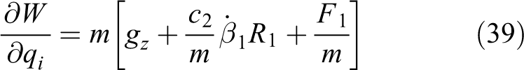
(2) Dynamics of the uniform linear upward motion along the inclined pipe
During the uniform linear upward motion along the inclined pipe,
(3) Dynamics of upward deceleration linear motion along the inclined pipe
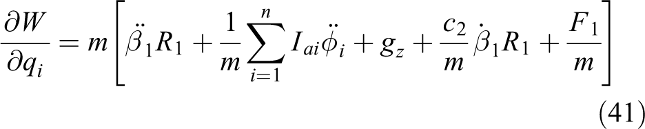
During the deceleration motion, the analysis is performed based on whether the driving force

In addition to friction and damping, when the driving force
Dynamics of the downward motion along the inclined pipe axis
(1) Dynamics of the downward acceleration start-up along the inclined pipe axis
In the downward acceleration motion along the inclined pipe axis, the analysis is performed based on whether the driving force

When the acceleration cannot be sustained by the gravity alone, and the driving force

(2) Dynamics of the uniform linear downward motion along the inclined pipe axis
When performing the uniform upward motion along the inclined pipe axis, both

The other case is, which the driving force
(3) Dynamics of the downward deceleration motion along the inclined pipe axis
There are two situations in the downward deceleration motion along the inclined pipe axis. One is a deceleration process with sufficient friction and damping effect, where the corresponding dynamics is the same as equation (26).
The other process is a braking process with the participation of the driving force
Dynamics of the rotation from high potential energy to low potential energy around the inclined pipe axis
As shown in Figure 2, during the process that the robot particle E 1 rotates anticlockwise around the axis y1 from A1 to A2, the potential energy gradually reduces, the gravity does positive work, and there are dynamic characteristics of different motion states.
(1) Dynamics of the accelerated rotation from the high potential energy to the low potential energy around the inclined pipe axis
When only the gravity causes the robot particle to perform accelerated rotation from the high potential energy to the low potential energy around the pipe, dynamics of the robot particle is expressed as follows

When the acceleration cannot be sustained by the gravity alone, and the driving force
(2) Dynamics of the uniform rotation process from the high potential energy to the low potential energy around the inclined pipe axis
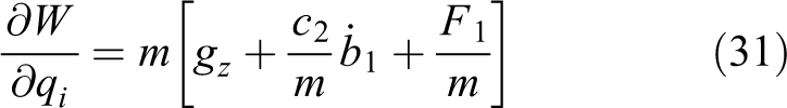
When only the gravity completes the uniform rotation, dynamics of the robot particle can be expressed in accordance with equation (22) as follows

When the gravity alone cannot make the robot particle perform continuous uniform rotation around the pipe axis, and the driving force

(3) Dynamics of the decelerated rotation process from the high potential energy to the low potential energy around the inclined pipe axis
When only the friction and the damping work together to make the robot particle perform decelerated rotation around the pipe axis, based on equation (22), dynamics of the robot particle is:

When the driving force
Dynamics of the rotation from the low potential energy to the high potential energy around the inclined pipe axis
During the process that the robot particle moves from A2 to A1, the potential energy gradually increases and the gravity does negative work. In this process, the robotic particle also has phases that the angular velocity increases, remains constant, and decreases around the pipe axis. Robotic particle has different dynamic properties during different phases of the motion.
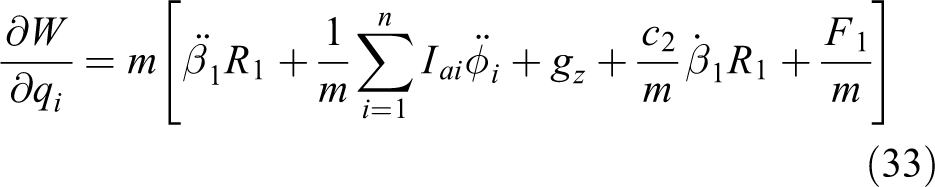
(1) Dynamics of the accelerated rotation from the low potential energy to the high potential energy around the inclined pipe axis
During the acceleration rotation from the low energy point A2 to the high energy point A1 around the inclined pipe axis, the kinetic and potential energies of the robot particle increase. Moreover, there is an energy consumption, so it is necessary to have the driving force

(2) Dynamics of the uniform rotation from the low potential energy to the high potential energy around the inclined pipe axis
During the uniform rotation from the low energy point A2 to the high energy point A1 around the axis, the robot particle motion parameters
(3) Dynamics of the decelerated rotation from the low potential energy to the high potential energy around the inclined pipe axis
During the decelerated rotation from the low energy point A2 to the high energy point A1, the gravity, friction, and the damping do negative work. Based on equation (22), dynamics of the deceleration rotation in which only these three forces work together is expressed as follows:

During the decelerated rotation from the low energy point A2 to the high energy point A1, the gravity, friction, and the damping do negative work, and the driving force
Dynamics of the spiral motion along the inclined pipe
The spiral motion is a synthetic motion, consisting linear and rotational motions. When
Conclusions
Through the analysis of the above research, the following conclusions can be drawn:
When a particle robot climbs on the pipe, the pipe’s axis and radius are studied as joints of the robot, and the dynamic model of the pipe climbing robot can be established, which allows for the dynamic study of the pipe climbing robot.
According to the description method of the particle robot’s position vector on the pipe, the dynamic equation of the particle robot can be obtained by a combination of the Lagrange–Newton–Euler improvement method.
According to the Lagrange–Newton–Euler improvement method, the range of the energy consumption D can be expanded, and the effect of friction has been included.
According to the dynamics of the pipe robot, dynamics of the accelerating motion, uniform velocity motion and the decelerating motion for a linear motion along the pipe, rotation around the pipe axis, and the spiral motion around the pipe axis are analyzed.
The dynamics of the climbing robot can be used to determine the value of driving force and the corresponding control mode.
Symbol annotation table.

Footnotes
Declaration of conflicting interests
The author(s) declared no potential conflicts of interest with respect to the research, authorship, and/or publication of this article.
Funding
The author(s) received no financial support for the research, authorship, and/or publication of this article.