
Abstract
It is a challenging task for operators to interact with the remote environment without its geometric and dynamic knowledge during teleoperation. In this article, a novel system architecture for implementing the translational object modeling and correction during remote interaction is proposed to reconstruct the haptic interaction and predict the object motion at the local virtual reality–based teleoperation. First, a stress mutation analysis method is proposed for segmenting the translational object motion into static phase, critical phase, and sliding phase. And the static limiting friction is originally estimated in the teleoperation area. Meanwhile, mass-damper-spring model and adapted Karnopp friction model are adopted for dynamic modeling in each phase. Second, a novel adaptive forgetting factor recursive least square method is studied for high-accuracy parameter estimation. With the estimated model parameters, the motion of the translational object is predicted at the master side. Meanwhile, for model consistence between the real and virtual environments, a new correction strategy is used to adaptively update the environment model. According to the experimental results, the translational object can be accurately modeled in real time, and its motion at the master side can be predicted precisely and corrected promptly.
Introductions
Teleoperation has been researched for several decades. It assists humans to implement risky, unreachable tasks by controlling the robot at a remote distance. Nowadays, teleoperation is mainly deployed into the outer space, the Deep Ocean, and other remote exploration areas. 1
The typical virtual reality (VR)-based teleoperation scheme is composed of five units: the human operator, the master system, the communication line, the slave system, and the real environment. 2 At the master side, the human operator inputs the commands to the master system by human–computer interaction devices. The command is sent to the slave system by the communication line. At the slave side, the slave system includes the robot and sensors. The robot accomplishes the tasks with reference to the commands received. The interaction signals captured by sensors during task implementation are fed back to the master system, which could increase the control performance of the teleoperation system.
In an actual teleoperation system, the existence of time delay distorts the transparency and stability of the teleoperation performance. Diverse researches have been done for eliminating the negative influences of time delay. Some recent surveys on teleoperation are described in the literature.3,4 The VR-based teleoperation system is widely applied for addressing longtime delay and poor virtual transparency problems which are typical challenges in the teleoperation research.5,6
A relevant control structure is also researched as the model-mediated teleoperation (MMT) 7 which is proposed by Hannaford. 8 A local VR environment is reconstructed and modeled approximating the real environment. A virtual robot which is consistent with the real robot is registered into the VR environment. The human operator manipulates the virtual robot at the master side. Meanwhile, the visual interaction and force reflection is provided to the human operator directly through the VR environment. The framework of the VR-based teleoperation system is shown in Figure 1.
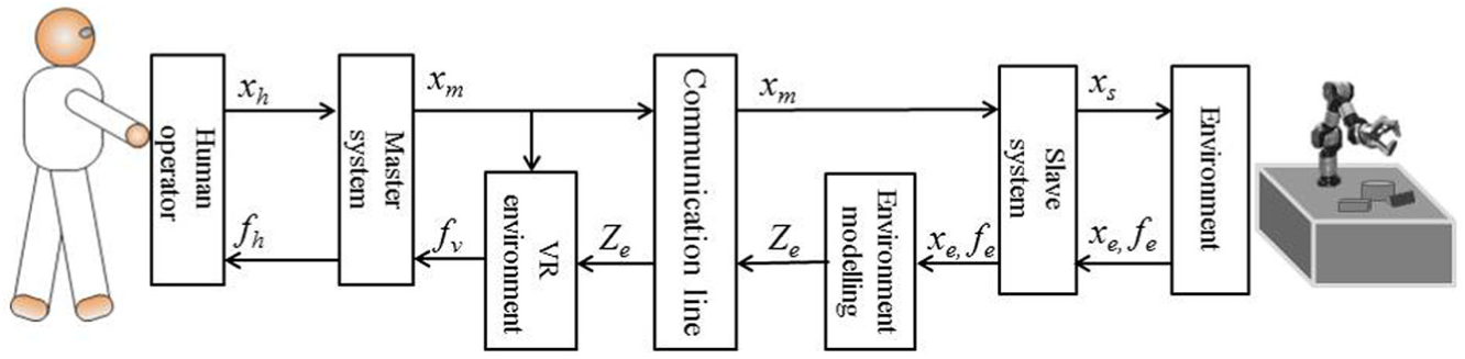
The typical structure of the VR-based teleoperation.
The key to reconstructing the VR environment is the dynamic modeling and geometric modeling of the real environment. If the model could perfectly describe the real environment, the stability and transparency properties of the teleoperation system can be guaranteed. However, it is still a challenge to implement the accurate dynamic modeling and geometric modeling of the environment in this study branch.
There are three major challenges in environment dynamic modeling. First, dynamic interaction signals are acquired mainly by the force sensor, but the acquired data are traditionally quite noisy. Second, even with accurate data acquisition, it is still difficult to realize an ideal model which could adequately represent the interaction processes. Last but not least, once modeling errors exist, it is crucial to correct the model online. Many types of researches have been done for handling these problems in robotic application. Li and Song 9 proposed a sliding-average least-square algorithm–based environment identification method for contact interaction with a static object. Haddadi and Hashtrudi-Zaad 10 did a survey on online environment dynamic identification. They detailed, summarized, and analyzed contact force modeling methods. Yamamoto et al. 11 reviewed three main online environment parameter identification methods for bilateral teleoperation, where the environment is assumed Kelvin–Voigt (KV) model. Jiang et al. 12 developed an intelligent controller to avoid the model errors between the virtual environment and the real environment. Some other relative researches can be found in the literature.13,14
Most of the previous works are toward interaction modeling with static objects. However, in a practical environment, some tasks often require interaction with movable objects, such as pushing objects to a target position. Thus, in order to reconstruct a physically realistic environment model, it is essential to consider the movable environment modeling. Xu et al. 15 proposed the initial idea to model movable object considering both rotation and translation in the VR-based teleoperation. However, they only considered the Coulomb sliding friction without demonstrating the transformation from the static status to the motion status, which is not consistent with the real condition. Besides, for the force feedback calculation, they used a simple linear proxy-haptic interaction point (HIP) algorithm, which cannot realistically predict object motion.
Along with the development of the three-dimensional (3D) scanners, it is much easier to realize the geometric modeling of the real environment recent years. A 3D geometric environment model is built using a stereo camera in Barth et al. 16 Xu et al. 17 proposed to use a point cloud model to represent the environment objects, which is mainly based on the local point clouds that lack detailed information of the full view of the real environment. In our previous work, 18 we proposed a method to realize 3D full view point cloud (FVPC) modeling of the real environment and implemented a point cloud augmented virtual reality (PCAVR) environment. However, in the geometric modeling, there is no research on the motion prediction for a movable object during teleoperation.
Considering the research background, in this article, a translational objects dynamic modeling and correction method for PCAVR-based teleoperation is proposed. First, the geometric modeling of the virtual environment is implemented referring to our previous work on PCAVR. Besides, for movable objects rendering, a predefined object is computer-aided design (CAD) modeled in the VR environment. Second, considering the complexity of friction property, the status of object motion is divided into three phases, static phase, critical phase, and motion phase. A stress mutation analysis (SMA) method is adopted for phase segmentation. In each state, the dynamic modeling is realized dependent on the corresponding physical model. Third, in the VR environment, the haptic rendering is accomplished based on the mapped dynamic model parameters, and with the rendered force, the object motion is predicted and refreshed real time. Finally, with the predicted object motion and the dynamic model parameters in the corresponding period, a correction strategy is designed for adaptively updating environment model which could reduce the transmission workload.
Compared with the relative previous work, our main contributions of the work are as follows:
To initially implement the motion status transition modeling based on an SMA method in a VR-based teleoperation system.
To propose a novel adaptive forgetting factor RLS (affRLS) method for high-accuracy parameter estimation.
To propose a new correction strategy to adaptively update environment model.
The remainder of the article is organized as follows. Section “System architecture” introduces the system architecture, while section “Modeling methodology” describes modeling methodology including the dynamic modeling and geometric modeling. Section “Model deviation correction” shows model deviation correction. In section “Simulation and experiment,” experiments are implemented for method demonstrated. Finally, some conclusions and future work are drawn in section “Conclusion.”
System architecture
Figure 2 depicts the proposed framework of the PCAVR-based teleoperation system. In this system, the PHANToM haptic device, with 6 degree-of-freedom (DOF) positional sensing and 3 DOFs force-output, is adopted as the human computer interface (HCI) for command input and force feedback actuator. At the slave side, a force sensor is equipped at the end effector of the real robot for real-time detecting contact force, while a Kinect sensor is used to capture the real environment at the slave side. The environment dynamic modeling is dependent on the data source from the sensors. SMA method is performed for classifying the object motion states into static phase, critical phase, and sliding phase. In each phase, the dynamic modeling is implemented accordingly. With the proposed affRLS online parameter estimation method, the model parameters are calculated real time. The estimated parameter is sent to the correction switch. The correction switch is responsible for deciding whether to update the parameters at the master side.

The proposed framework of the VR-based teleoperation system.
At the master side, the geometric modeling is accomplished based on the PCAVR construction method before manipulation. However, it is difficult to real-time update the motion of point-structured object. In order to fast refresh and update the motion of an object, a corresponding 3D CAD model is constructed replacing the point-structured object. The human operator controls the virtual robot to interact with the VR environment. Meanwhile, the command is sent to the slave side for real robot manipulation. In the VR environment, the interaction force is rendered based on the estimated parameters from the slave side. The human operator can feel the contact force feedback real time through the haptic device. According to the value of interaction force, the target object motion is predicted and the visual rendering will be refreshed relatively. Meanwhile, the predicted object interaction information including the motion phase, contact force, and predicted position will be transmitted to the correction switch at the slave side. The correction switch is designed considering the object interaction information in the VR environment and the real interaction information.
In order to realize the proposed framework in the teleoperation system, there are several challenges as follows:
Phase segmentation. For the complexity of the friction, it is difficult to detect the pre-sliding process because of large disturbances in zero velocity. If the property of the object is isotropic, assuming the motion of the robot end effector is same; thus, the relationship between the pressure and the deformation information is similar. During the motion in the X or Y axis, if the robot moves at the same velocity, the stress mutation situations compared to the pressure–deformation relationship in Z axis can be analyzed for phase segmentation. Besides, in order to mainly focus on status transition modeling, only the translation property will be considered.
Dynamic modeling in different states. In a complete motion procedure, the resultant force based on the gravity, friction force, and contact force leads to the motion of an object. As this procedure is nonlinear and more parameters need to be considered, it is a challenge to precisely modeling the dynamic procedure.
Correction strategy. It is a risk for teleoperation if there exists model mismatching. Updating the model parameters real time will aggravate the communication workload. For high modeling accuracy and low communication workload, a correction strategy based on parameter change and motion prediction error are proposed.
Modeling methodology
Dynamic modeling of environment
For reconstructing the dynamic model in the virtual environment, it is essential to consider the relationship between the force and the motion of objects. During the interaction between the robot and the object, there are three main motion phases of the objects including static phase, critical phase, and sliding phase. When the robot contacts with the object at the beginning, the object will not move until the contact force is larger than other resultant force including the object gravity force and the friction force. Equation (1) describes the force model of the object

The force analysis is shown in Figure 3. Thus, in order to reconstruct the dynamic procedure, the contact force modeling and friction force modeling need to be studied. In this article, the dynamic modeling for movable objects mainly focuses on translation in an X-Y plane. The robot end-effector tool is assumed rigid with a small contact area. The dynamic property of the object is homogeneous. Besides, all forces are considered effect along the X or Y central axis which means no rotation occurs.
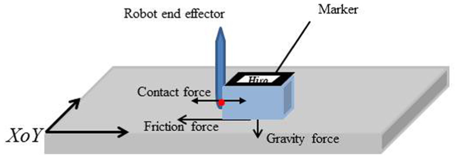
The applied force analysis.
Dynamic modeling of contact force
During the contact between two objects, the bodies suffer elastic and/or plastic deformation, with the loss of energy in various forms. There are mainly three basic contact force models including KV model, linear mass-damper-spring (MDS) model, and the Hunt–Crossley (HC) model. 19 In robot teleoperation application, the KV model is widely used for its computation simplicity and parameter estimation ease.20,21 However, the KV model is proved to be physical inconsistent with the real contact because of discontinuities during rebound. The HC model shows a good property on the consistency with the real contact. 22 However, it is much more suitable for soft contact modeling. Besides, for its nonlinearity, its computation is much more complicated than KV model. As the linear MDS modeling method allows more modeling freedoms with linearity property, in the proposed system, we will adopt the MDS model for contact dynamic modeling in the proposed system.
MDS model
The MDS model is a linear environment model. The mechanical equivalent of this model is composed of a mass bulk, a spring, and a damper. The mathematic description is shown in equation (2)

where k and b are the stiffness and damping parameters while m is the parameter representing the mass of the contact area. Besides, x(t) is the penetration depth,
affRLS-based parameter estimation
In the literature,9,23 the MDS model is adopted for contact modeling. As any parameter change could lead to bad modeling, it is crucial for real-time parameter estimation. The ability to track abrupt changes during operation is vital for choosing a parameter estimation method. In previous teleoperation system, the block-wise sliding least squares (BSLS) method is used. Even though the tracking performance is relatively good, the computational complexity is in the order of O (N 3 ) which grows as the block size increases. The exponentially weighted recursive least square (EWRLS) estimation method is proven lower computational complexity in the order of O (N2). However, it cannot adaptively change the weight which can better observe the abrupt changes of values. In this article, we propose a novel affRLS method for online parameter estimation.
The measured force described by MDS model is shown by equation (3)

where ε is the measured noise, which is the error resulting from the estimation of m, b, and k.
Let,
Then

The EWRLS method has been widely used for fast online parameter estimation in robotic applications. This method is particularly more effective in tracking variations in system parameters. The basic equations are shown as follows


where n is the time index in the discrete domain, P is the covariance matrix, and λ (0 < λ ≤ 1) is the forgetting factor. The larger the λ, the less important the influence old data play. Meanwhile, the esti-mated parameters can be calculated from
The affRLS method is proposed against the problems with EWRLS method by adaptively modifying the value of forgetting factors. A change detecting theory is applied to detect parameter changes. The prediction error of a pre-set length window in the neighbor region is calculated as equation (7)

where L is the neighbor window length,

Dynamic modeling of friction force
In the VR-based teleoperation, the virtual object motion prediction depends on the accuracy of contact force modeling and friction force modeling. However, the modeling of friction force is kind of cumbersome because of its discontinuity from static phase to sliding phase. There are few teleoperation applications which consider the friction modeling for translational objects motion prediction in robot teleoperation. Xu adopted the conventional coulomb friction force model for motion estimation. 15 Nonetheless, the nonlinearity of the Coulomb model at zero velocity adds difficulties to modeling because it is hard to detect an exact zero velocity. Richard et al. 24 realized a friction identification method for surface haptic display without a realistic force reconstruction for haptic rendering. Even though there are several friction models for simulation, 25 it is challenging to implement online friction parameter estimation in the teleoperation system. In the proposed system, we will use a modified Karnopp friction model for friction dynamic modeling.
Adapted Karnopp friction model
The key issue of friction model is the discontinuous property when object motion velocity exceeds zero. At the static phase, the friction magnitude is equal to the net force from other sources. But, once the net force from other sources is larger than the limiting static friction, the object will move. The friction dynamic modeling plays an important role in the motion prediction in the VR environment. As it is tough to detect the time point at exact zero velocity, an approach to distinguish the three phases is to use a threshold velocity below which the object is treated as the static phase which is proposed by Karnopp. 26 However, in the proposed teleoperation system, the motion detection is hard to achieve the micrometer resolution by the traditional tracking methods. Thus, the Karnopp model is adapted, and the states segmentation method is not depending on the velocity but the SMA method. The friction model is described by equation (8) as follows
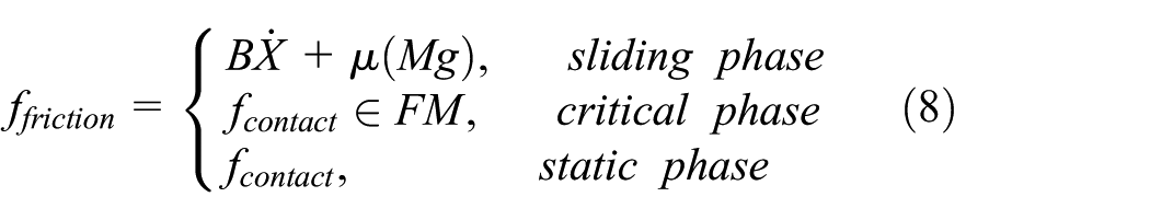
where μ is the sliding friction coefficient, M is the mass of the interaction object, B is the viscous parameter, g is the acceleration of gravity, and FM is the limiting static friction range.
In the proposed system, the accurate friction modeling plays an essential role in the motion prediction for the precise geometric modeling and updating. Therefore, the tracking on critical phase is the foremost job. As discussed above, the accuracy of motion detection is much lower than a micrometer, the SMA method is proposed for limiting static friction inspection.
SMA method
Considering the interaction object is isotropic, the relationships between the pressure and the deformation information in X, Y, and Z axis are similar if the motion of the robot is the same. Thus, assuming the object is static, with the estimated dynamic parameters of the contact procedure, the force change line can be predicted during pushing the object. The motion phases are segmented by comparing the predicted force change line with the real force change line. Three steps are applied for segmenting the motion phases and the main procedures are shown in Figure 4.
Step 1. Move the robot end effector along the Z axis of the object; record the contact force data, position, and penetration distance; and estimate the contact dynamic model parameters.
Step 2. Move the robot end effector along the X/Y axis until the object slides, record the contact force data, position and penetration distance. This force data is plotted as the current motion curve. With the estimated parameters, predict the contact force change line which is treated as the predicted motion curve.
Step 3. Segment the phases manually by observing the force mutation points.
Step 4. Repeat steps 2 and 3, get the range of limiting static friction.

Motion phase segmentation method.
A detailed observation procedure is shown in Figure 5. The green line describes the real force when pushing the object, while the red line shows the predicted contact force with the estimated contact model parameters. The cross area in the black circle is the location of critical phase. The limiting static friction can be observed from this area.
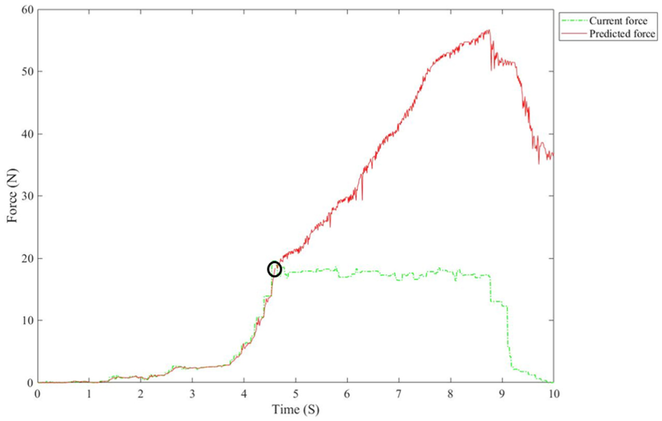
Motion phase segmentation schematic diagram.
For the accuracy guarantee, the main procedures need to be repeated for particular times N, thus, a more accurate limiting static friction to segment three phases can be confirmed. The limiting static friction can be determined by the average of the data values at the cross point using equation (9). In practice, the accurate limiting static friction data are hardly to be detected for the force sensor measurement accuracy, thus, the standard deviation (STD) is used for a critical phase definition. When the pushing contact force is in the range of Fin_critical_phase, the motion of the object is predicted as the critical phase. As well, when the pushing contact force is larger than the maximum Fin_critical_phase, the motion is decided as the motion phase, vice versa, it is the static phase


Online parameter estimation based on affRLS
Since the limiting static friction FM is estimated by the SMA method in the critical phase, the parameters in the sliding phase are still unknown. After phase segmentation, the force model of the whole interaction process in the sliding phase is described as equation (11)

where τ is the modeling error.
Let
Then, the affRLS method will be applied to implement the parameter estimation.
Geometric modeling based on point cloud
PCAVR environment
In this proposed system, the PCAVR construction method 18 is applied at the master side for its accurate description of the unstructured environment. Using this method, the point cloud of the real environment is first acquired by Kinect sensors at the slave side. Second, registrate the point cloud into the robot coordinate by the marker, and this marker is labeled as PC_marker. Then, the VR environment representing the real environment is constructed.
In this article, the position of the interaction objects is real time tracked as the ARToolKit provides with an open source development kit for marker tracking. 27 A specific marker which is set as O_marker is placed on the surface of the object where is easily captured by the Kinect sensor as shown in Figure 6. In this way, the real-time position of the object relative to the robot base coordinate can be calculated. In the VR environment, the predicted motion of the object is described by a relative 3D model.
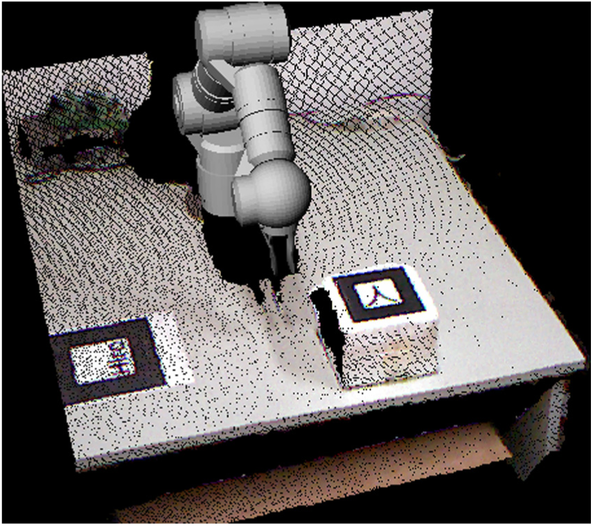
Point cloud augmented virtual reality environment.
Target object position refreshing based on haptic rendering
In the VR environment, the HIP represents the phantom end effector while the proxy stands for virtual robot end effector. In the free space, the proxy tracks the HIP. When contacts happen, the proxy is constrained by the object surface. In this way, the contact force can be reconstructed by considering the relative motion between the HIP and the proxy together with the estimated dynamic parameters as shown in equation (12)

where
If the estimated contact force exceeds the limited static friction FM, the virtual object starts sliding and the friction becomes the sliding friction modeling. In the estimated sliding phase, the motion of the virtual object needs to be predicted according to the estimated friction model parameters

The motion of the virtual object is calculated according to equation (14), where Me represents the estimated mass value of the object, μ is the estimated sliding friction coefficient, and Be is the estimated viscous parameter. Assuming the time cycle is T at the master side, by equation transformation (equations (14) and (15)), the object position can be calculated and real-time updated for visual rendering


Model deviation correction
During the teleoperation, due to the calculation accuracy, limited bandwidth, and sensor noises, both the geometric and dynamic modeling cannot be perfectly consistent with the real environment all the time. It is risky for operation based on the VR environment which is largely deviated from the real environment. Besides, real-time correction strategy is not a suitable way for bandwidth limited communication and stable operation. Thus, the model deviation definition and model correction strategy are crucial for the authenticity and stability of the VR-based teleoperation.
In the proposed system, the limiting static friction can be estimated using the SMA method. For simplifying the correction and updating procedure, the limiting static friction is estimated by 10 repeated tests during the prior operation so that a precise limiting static friction parameter is measured. Therefore, only the geometric and dynamic modeling in the static phase and sliding phase is considered for model deviation correction. For a clear description, predicted motion phase, predicted object position, and predictive contact force are defined as Ph_m, P_m, and F_m, respectively. Meanwhile, the relative motion phase, object position, and contact force in the execution procedure are Ph_s, P_s, and F_s, respectively. The object motion phase is fundamental for modeling method classification. Thus, the motion phase is the prior reference for modeling correction. The following two cases describe the issue.
Case 1. Estimated motion phase and the real motion phase are same. Subcase 1.1. Ph_m and Ph_s are the static phase and contacts happen at both sides, but
Subcase 1.2. Ph_m and Ph_s are the static phase and contacts happen only at one side. Subcase 1.3. Ph_m and Ph_s are the motion phase


Case 2. Ph_m is different from Ph_s.
For Subcase 1.1, the predicted object motion is the static phase as same as the executed object motion, and both the predicted robot position and the real robot position after execution are in contact with the object. If a deviation of the contact force is larger than the pre-set force threshold F_threshold, the contact dynamic modeling parameters need to be updated. In this way, it is not necessary to transmit the estimated contact dynamic model parameters. The F_threshold is set according to the just noticeable difference (JND) for force (10% for the forearm, refer to Samur 28 ) in the human haptic perception research, here the F_threshold is adaptive

For Subcase 1.2, the predicted object motion is the static phase as same as the executed object motion, but only one side is in contact with the object. Two situations may happen. One is that the predicted robot is in contact with the object and the real robot is in free space, which can be made up by updating the object position. The other is that the predicted robot is in free space and the real robot is in contact with object, which is dangerous to update the object position directly in the VR environment. In this situation, it is urgent to move the virtual robot along the contact force away from the object until no contact at both sides, then update the object position.
For Subcase 1.3, the predicted object motion is the sliding phase as same as the executed object motion, but the deviation of the predicted object position and the real object position is larger than the pre-set position threshold P_threshold. If the deviation of contact force is under the force threshold F_threshold, the sliding friction force dynamic modeling parameters need to be updated. Otherwise, the contact dynamic modeling parameters need to be updated. The P_threshold is associated with the marker detection resolution and data resolution of the Kinect camera, here, the P_threshold is set as 3 mm.
For Case 2, the predicted object motion is different from the executed object motion. This situation is much more complicated than the upper cases, all of the contact force model, friction force dynamic model, and object position may cause large deviation. Thus, it is an effective way to keep the virtual and real robot away from the object, update the object position, and reconduct the dynamic modeling of the real object.
Simulation and experiment
System setup
The method evaluation is implemented on an experimental teleoperation system. The teleoperation system is composed of three parts: the master platform, the TCP/IP communication line, and the slave platform. The master platform consists of the PHANToM haptic device which provides with position measurement and force feedback in real time, the reconstructed VR environment which relies on the OpenGL rendering interface. In the slave side, the SChunk Robot arm is the task performer as shown in Figure 7. A Kinect sensor is adopted to capture the real environment, and the FTM75 is set at the end of the robot arm. The ROS software interface is used to control the robot motion, while the PCL library and the OpenCV library are applied to realize 3D marker tracking. Both kernel processors work on 3.2 GHz. The experimental teleoperation system is setup as shown in Figure 7. To prove the effectivity of the proposed method in detail, two material boards are fixed upon the surface of a cubic object, one is foamed plastic FP_object and the other is rubber R_object. The object is sized as 17.5 cm × 17.5 cm × 12.5 cm. Besides, it is critical to reduce the noises and disturbances of force sensors and position tracking, which could lead to a poor effect on the later modeling. In this system, a data pre-filter mainly based on singular point removal and the moving average method is applied to obtain smooth and accurate data.
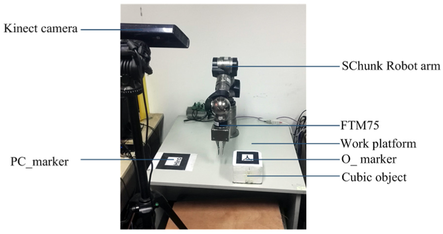
The experimental teleoperation system.
Contact force tracking
Based on the system setup, the contact force modeling evaluation is conducted first. In order to specially observe the contact force modeling method, the time delay is set as zero. The operation is asked to control the robot to contact with the target objects FP_object and R_object from the Z axis in the static phase, which means a pushing operation from the upside of the object. The real model parameters of the object are unknown. The estimation accuracy of contact force and tracking convergence speed are evaluated. The proposed method is compared with the BSLS method and the EWRLS method in estimation accuracy and tracking convergence speed, respectively. For comparison, the window length of BSLS method is set 30 empirically.
The estimated force is shown in Figure 8(a) and (c) while the relative error between the real force and the estimated force is shown in Figure 8(b) and (d). The green line describes the performance of BSLS method, the blue line presents the EWRLS performance and the red line shows the affRLS performance. As we can see from Figure 8, the affRLS method could track the force at a very fast coverage speed, and the relative errors between the real force and the estimated force reach a high accuracy about 10% much faster than the other methods. Besides, even in a steady state between 2 and 4 s, the estimated force error with the affRLS method is still lower than the errors with other methods.
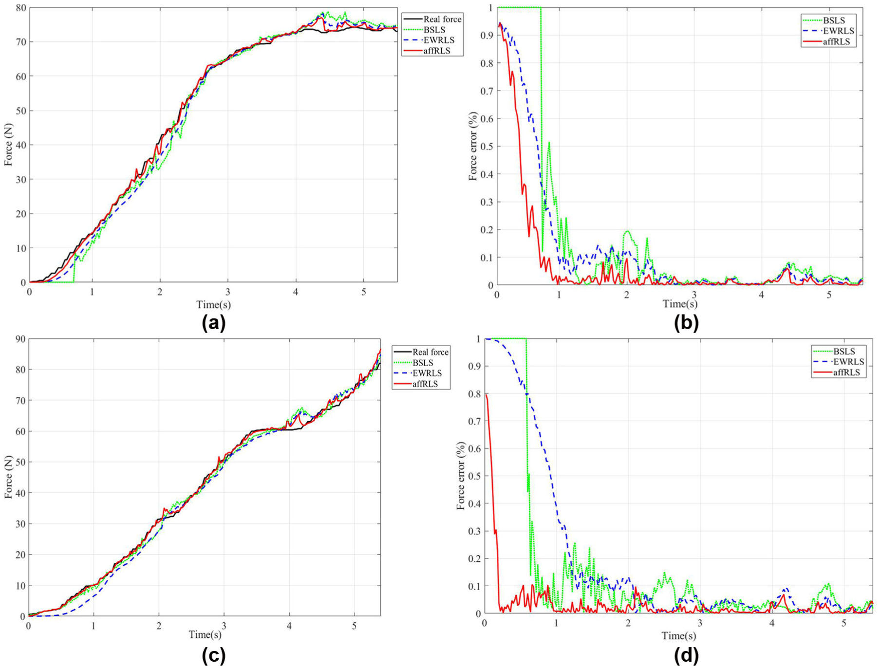
(a and c) Estimated forces of FP_object and R_object and (b and d) the relative force error of FP_object and R_object.
During the estimation at the slave side, the estimated parameters of MDS model are transmitted to the master side for haptic rendering and object motion prediction in the VR environment at the master side. If the transmission is implemented real time, the bandwidth costs much. Thus, according to the proposed model deviation correction method, mainly for Subcase 1 in Case 1, the parameters will be updated and transmitted only when the deviation is larger than 10% of real force. As shown in Figure 9(a) and (b), the real-time estimated parameters during contact vary too often in the red line. Using the proposed correction method, the updated parameters which are transmitted to the master side are shown in dotted yellow line, which changes in a much lower frequency. Besides, force error between the reconstructed force and the real force is below 10% shown in Figure 9(c) and (d) as designed except the initial section. In this way, not only the contact force reconstruction accuracy but also the less stressful communication bandwidth can be accomplished.

(a and c) Estimated parameters and force error of FP_object and (b and d) estimated parameters and force error of R_object.
In the initial contact phase before 3 s, the error is relatively larger than that between 3 and 4.5 s. It is easy to find that the updated parameters during 3–4.5 s are extremely stable. These parameters can be used for motion prediction in the virtual environment as shown in Table 1. The data are plausible because the moving is quite slow during operation. The acceleration and the velocity are nearly zero. The fluctuation of the estimated mass and damping items has little influence on the force estimation.
Estimated contact model parameters.

Position tracking
According to the proposed SMA method, the limiting static friction force of the FP_object and the R_object is 9.57 and 40.62, respectively. Meanwhile, the STD of the critical static force is 0.861 and 2.346. With the definition of critical phase, the sliding motion is determined accordingly. The sliding force parameter estimation is implemented using the similar way to the contact force tracking. The sliding friction coefficient, the mass of the object, and the viscous parameter are estimated as shown in Table 2.
Estimated friction model parameters.

The objects used in the experiment are weighted as 3.0 and 3.5 kg for FP_object and R_object, respectively. It is obvious that the relative error between the estimated weight and the real weight is around 5%, which is good for motion estimation. With the estimated friction force model parameters, the performance of the object position tracking in the master side can be evaluated. An experiment is conducted without time delay and with pre-set estimated parameters. The motion in the sliding status is specifically observed. When pushing the object sliding along the Y axis, the predicted motion of the object at the master side and the real motion at the slave side are compared as shown in Figure 10. The black lines describe the real position of the object while the red lines show the predicted object position. As shown in Figure 10, the error is about 3 mm. This result shows that the estimated parameters are accurate while the proposed position refreshing method works well.
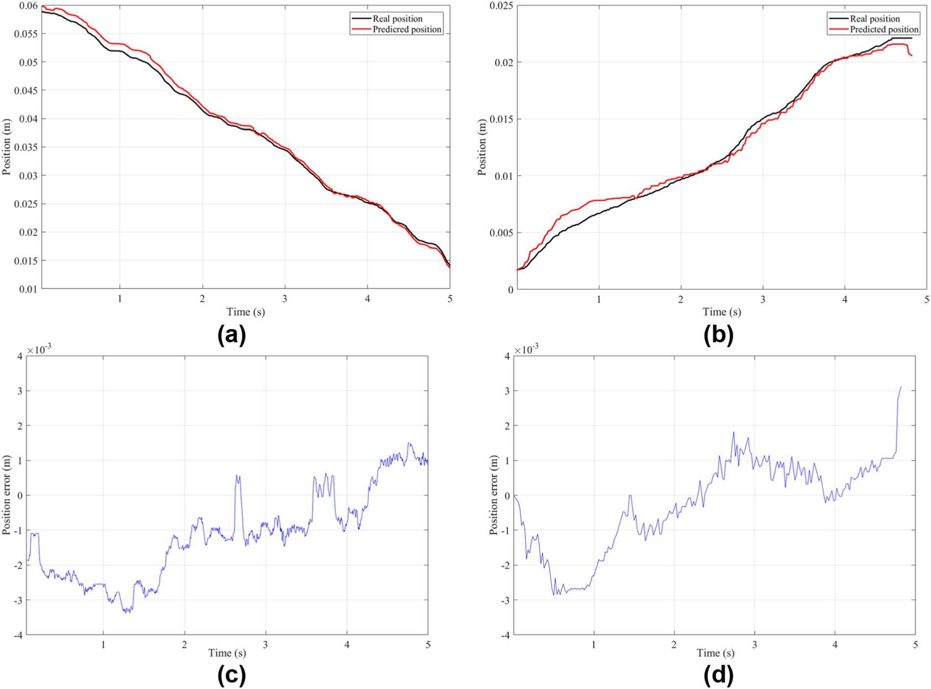
(a) Position tracking of FP_object, (b) position tracking of R_object, (c) position error of FP_object, and (d) position error of R_object.
System evaluation
For the time delay exists in the teleoperation system, it is crucial to test the system performance with the proposed framework by setting forward and backward time delay as 200 ms including the system time delay. The real robot is controlled to push FP_object first and then push R_object along one axis. The force on the end effector and the object position mainly in Y axis are tracked. Meanwhile, with the estimated parameters, the virtual force and the virtual object position are also estimated and compared with the real force and position. For easier observation, the real force and real object position are shifted by the backward time delay.
As shown in Figure 11, 10 key time nodes are marked. Before time t5, the robot end effector is pushing FP_object, while the robot end effector is pushing R_object after time t6. From t1 to t2, the force applied on the FP_object is smaller than the least limiting static friction. Between t2 and t3, the R_object stays in the limiting static phase with no motion. When the applied force is larger than the max limiting static friction after t3, the R_object moves in the sliding phase. At time t4, the applied force is smaller than the sliding friction, the R_object motion is stopped. Later, no force is applied on R_object, and the R_object stays static. The robot end effector moves in a free space until time t6. The same conditions happen on FP_object between t6 and t10. The position error occurs mainly in the transition phases from the static phase to the motion phase and from the motion phase to the static phase.

System evaluation.
Conclusion
In this article, translational objects dynamic modeling and correction method for PCAVR-based teleoperation is described. The translation object dynamic modeling in three motion phases is implemented. In the static phase, the static limiting friction is estimated for motion phase segmentation. The object material physical parameters are estimated, as well as the motion modeling parameters. With the estimated parameters, the object motion in the VR environment is predicted. From the experiments, it is obvious that the proposed dynamic modeling method works well and effectively. The correction method can guarantee the modeling accuracy and reduce the transition bandwidth load. However, only the translation motion on cubic objects are evaluated in our system which is limited in the real environment. In view of the limitations, some rotational modeling methods will be further researched in the future work.
Footnotes
Handling Editor: Zhaojie Ju
Declaration of conflicting interests
The author(s) declared no potential conflicts of interest with respect to the research, authorship, and/or publication of this article.
Funding
The author(s) disclosed receipt of the following financial support for the research, authorship, and/or publication of this article: This paper was funded by National Key Research and Development Program of China (grant number 2016YFB1001301), National Science Foundation for Distinguished Young Scholars of China (grant number 61325018), Natural Science Foundation of China (grant number 61403080), and Natural Science Foundation of Jiangsu Province (grant number BK20140641).