
Abstract
To improve the positioning accuracy of tunnels for anterior cruciate ligament (ACL) reconstruction, we proposed an ACL reconstruction robotic positioning system based on anatomical characteristics. The system includes a preoperative path planning system, an intraoperative path planning system, and a navigation and positioning system. Brahmet line, anterior, and posterior cortical lines are used for registration of preoperative computed tomography (CT) images and intraoperative X-ray images. A new calibrator of C-arm is applied to establish the mapping between medical images and surgical space. Tunnels for ACL reconstruction can be built anatomically by the robot. The accuracy of the path planning system is 1.73 mm in the four dry bones experiments and 2.17 mm in the two cadaver experiments. The accuracy meets the accuracy requirement of ACL construction surgery.
Introduction
Precise positioning of femoral and tibial tunnel is the key to anterior cruciate ligament (ACL) reconstruction. Arthroscopic ACL reconstruction is a common method in the clinic. However, it is difficult to build the ACL tunnels accurately due to limitations of operation space and surgical view field under arthroscope. 1,2 ACLs are eliminated completely for accurate positioning of femoral and tibial tunnels in the past. But reconstruction surgery with remnants preservation of the cruciate ligaments has been a trend of ACL reconstruction technology. 3 –5 This will increase the difficulty of tunnels placement.
Researches of Hua et al., 6 Eichhom, 7 and Angelini et al. 8 show that computer-assisted navigation system can not only improve the accuracy of ACL reconstruction tunnels but also reduce the learning curve of surgeons. Navigation systems for ACL reconstruction started in 2005. These navigation systems can be classified into three types: point cloud based, 3-D printing based, and intraoperative X-ray image based. (1) KneeNav 9 developed by Medical Center of Pittsburgh University and Carnegie Mellon University, OrthoPilot developed by Tuttlingen corporation in Germany, 10 Bone Morping 11 developed by Praxim in France, and an image-free navigation system developed by Beihang University 12 are all point cloud-based system. In point cloud-based system, intraoperative anatomical features are collected by a probe which would result in additional trauma. And more importantly, due to the attachment of soft tissues, the femoral and tibial surface might not be smooth, which would cause reconstruction of knee joint failure. (2) Large exposures in guide plate surgery based on 3-D printing technology 13 which made ACL reconstruction an open surgery. And the 3-D printing-based method may be ineffective if residual ACL fibers are saved during surgery. (3) A computer-assisted navigation system based on X-ray 14 can improve the accuracy and reproducibility of the tunnel placement. Quadrant method 15 and Klos method 16 under standard anteroposterior (AP) and lateral (LAT) position X-ray images of knee joint are used to plan the reconstruction tunnels. Although ACL tunnels could be located accurately with ACL remnant preservation using intraoperative X-ray image-based method, individual differences are ignored, 17 which would make the ACL tunnel un-anatomical.
An ACL reconstruction robotic positioning system based on anatomical characteristics (ACL-RRPS-AC) is proposed in this article. The system consists of a preoperative path planning system, an intraoperative path planning system, and a navigation and positioning system. Registration of preoperative CT images and intraoperative X-ray images is based on AC like Brahmet line, anterior, and posterior cortical lines. A new calibrator of C-arm with points distributed conical helically is applied to establish the mapping between medical images and surgical space. As the posterior cortex which is about 2 mm behind the femoral attachment of ACL should be retained, 18 the accuracy of tunnels for ACL reconstruction should below 3 mm. The accuracy of the path planning system is 1.73 mm in the four dry bones experiments and 2.17 mm in the two cadaver experiments. The reconstruction tunnels can not only be planned anatomically with ACL remnant preserved but also be paced accurately satisfying the clinical requirements. The surgery time of ACL reconstruction is 30–40 min, which is very close to the traditional arthroscopic ACL reconstruction.
Materials and methods
3-D and 2-D registration based on osseous anatomical landmarks
X-ray images at standard AP and LAT projections are common methods in sports medicine surgery: in standard AP X-ray image, the anteromedial condyle and the anterolateral condyle should overlap each other; in standard LAT X-ray image, front and posterior margin of tibial should overlap each other, and the tibial intercondylar spine should be just in the middle of the femoral intercondylar fossa.
As the relationship between osseous anatomical landmarks and the start point and end point of ACL tunnel are the same at AP and LAT projections both in preoperative CT data and in intraoperative X-ray images, we can establish a 3-D and 2-D registration method based on osseous anatomical landmarks.
2-D coordinate system
Bird
19
investigated a novel measuring technique based on identifying the proximal border of the articular cartilage and using a specific ruler parallel to the femoral axis to locate the origin of the ACL. At standard AP and LAT projections, 2-D femoral coordinate systems can be constructed based on Brahmet line, and 2-D tibia coordinate systems can be constructed based on anterior and posterior cortical lines (Figure 1):
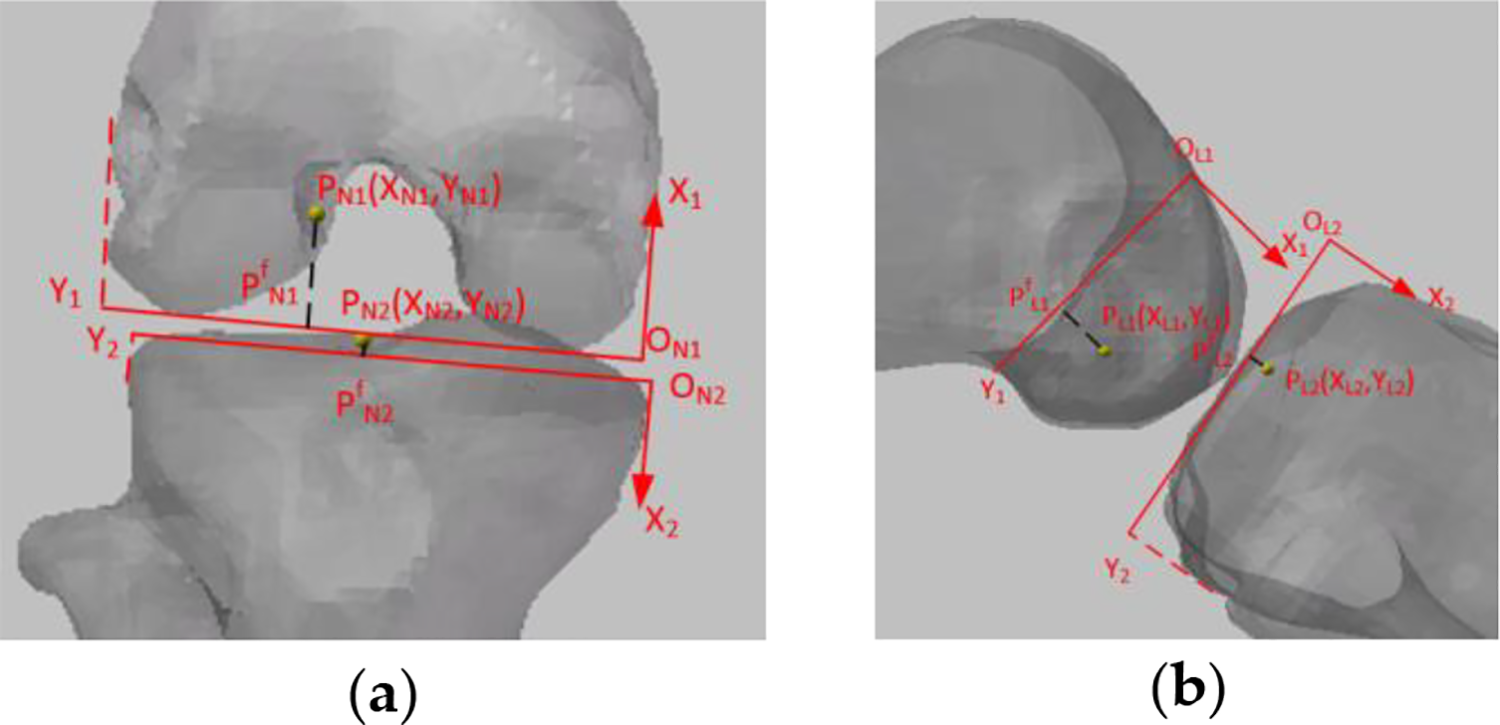
3-D and 2-D registration based on osseous anatomical landmarks. (a) 2-D coordinate system at AP projection and (b) 2-D coordinate system at LAT projection. AP: anteroposterior; LAT: lateral.

Relationship between preoperative CT data and intraoperative X-ray images
Preoperative coordinates of femoral and tibial end points are planned in ACL path planning system using CT data. The normalized coordinates of planned points at standard AP and LAT projections in the preoperative 2-D coordinates system can be calculated and the intraoperative 2-D coordinates system can be established according to the method in the “2-D coordinate system” section. If

where
Calibration of C-arm
The calibration of C-arm is to establish the mapping between surgical space and X-ray image space. 20 It is necessary for surgical navigation system. Geometric distortions (Figure 3(b)) in the process of X-ray imaging 21 –23 affect the accuracy of calibration of C-arm. To improve the calibration accuracy at the target, we developed a calibrator with points distributed conical helically (UDCSC) (Figure 2(a)). 24 Four visual markers were distributed on the four planes of the calibrator for navigation (Figure 2(b)). Twelve steel balls with a diameter of 4 mm were embedded in the calibrator as the fiducial points for calibration (Figure 2(c)). The calibrator could be placed on the knee and this is applied in this article to improve the calibration accuracy of C-arm.

Design of online C-arm calibrator 24 : (a) design model of calibrator, (b) distribution of visual markers, and (c) distribution of 12 fiducial points.

Image rectification. 24 (a) Rectification plate, (b) unrectified image, and (c) rectified image.
To correct the geometric distortion in the process of X-ray imaging, 25 a polynomial fitting-based global correction method is applied to rectify X-ray images of C-arm. 26 A rectification plate with 48 steel balls was uniformly distributed (Figure 3(a)) fixed at the receiving end of C-arm.
After rectification of image distortion, C-arm can be considered an ideal pinhole model. 27,28 Eleven internal and external parameters of a pinhole model could be calculated by direct linear transform. If Pa and Pl in X-ray images are the projection points of the same space point P at AP and LAT projections, respectively, the world coordinates of P can be calculated by a back projection model.
An ACL RRPS
The ACL RRPS includes a preoperative path planning system, an intraoperative path planning system, and a navigation and positioning system.
Preoperative planning system
An ACL reconstruction preoperative planning software (Figure 4(a)) is developed by C++ based on Qt framework. VTK and CTK are used to render the 3-D model. For the anatomical positioning of ACL reconstruction tunnel, the end point of ACL tunnel should be planned at the anatomical location. Ferretti et al., 29 Edwards et al., 30 and Siebold et al. 31 have done research on the locations of femoral end point. We can plan of femoral and tibial end points in this system (Figure 4(b) and (c)) according to their results. The preoperative normalized coordinates of end points of femur and tibia can be calculated through the method in the “2-D coordinate system” section.

ACL path planning system based on osseous anatomical landmarks. (a) Software interface, (b) femoral end point planning, and (c) tibial end point planning. ACL: anterior cruciate ligament.
Intraoperative planning system
As shown in Figure 5, the yellow dotted line is the planned femur tunnel, and the green, blue, and red dotted line segments are assistance lines for the planned end point. The straight red dotted line is the line of sight of the planned point under a selected perspective and that line of sight can be used to map the planned points in the AP and LAT images. The intraoperative 2-D coordinate system can be established through the method in the “2-D coordinate system” section. The intraoperative normalized coordinates of end points of femur and tibia can be calculated through the method in the “Relationship between preoperative CT data and intraoperative X-ray images” section.
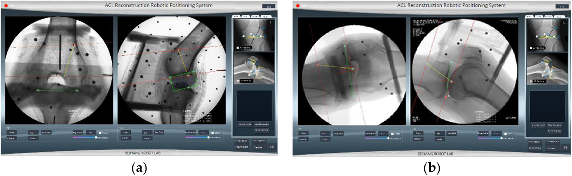
Intraoperative path planning system. (a) The LAT view and the posterior view of the distal femur and (b) the LAT view and the posterior view of tibia. LAT: lateral.
Navigation and positioning system
Structure of ACL reconstruction navigation and positioning system
ACL reconstruction navigation and positioning system (Figure 6) consists of a visual tracking sensors (Micron Tracker, Claron Technology Inc., Canada), a navigation software, a robot arm, a C-arm, and a calibrator of C-arm. There are visual markers at the end-effecter of the robot arm, on the calibrator, and on the tibial and femoral fixators. Surgical space, robotic space, and space of C-arm are unified into visual coordinate system. The planned tunnels and the position information are converted to robotic movements in the navigation software. Robot arm can move the planned route.

Structure of ACL reconstruction navigation and positioning system. ACL: anterior cruciate ligament.
Calculation of pixel coordinates of planning points in X-ray images
Pixel coordinates of preoperative planned end points in intraoperative X-ray images are needed in navigation system. Therefore, the normalized coordinates of the end points should be transferred into pixel coordinates. The normalized 2-D coordinates of femoral and tibial end points calculated by equation (2) can be transferred to the un-normalized 2-D coordinates of femoral and tibial end points can be calculated by equation (1). If

where
Calculation of planning points in visual space
The coordinate systems of the Micron Tracker, robot, calibrator, X-ray image, tibia, and femur (Figure 7) are


Spatial transformation of navigation system. 24


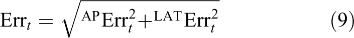
Target positioning error
If

Workflow of navigation system
The workflow of navigation is as follows (Figure 8): (1) preoperative path planning are conducted in preoperative path planning system using CT data; (2) intraoperative standard AP and LAT X-ray images of femur and tibia are captured and rectified; (3) femoral and tibial end points are planned in rectified images; (4) C-arm are calibrated by the method in the “Calibration of C-arm” section; (5) coordinates of end points in robot system are calculated by the method in the “An ACL RRPS” section; (6) robot arm moves the planning positions; and (7) errors of end points at AP and LAT projections are recorded.
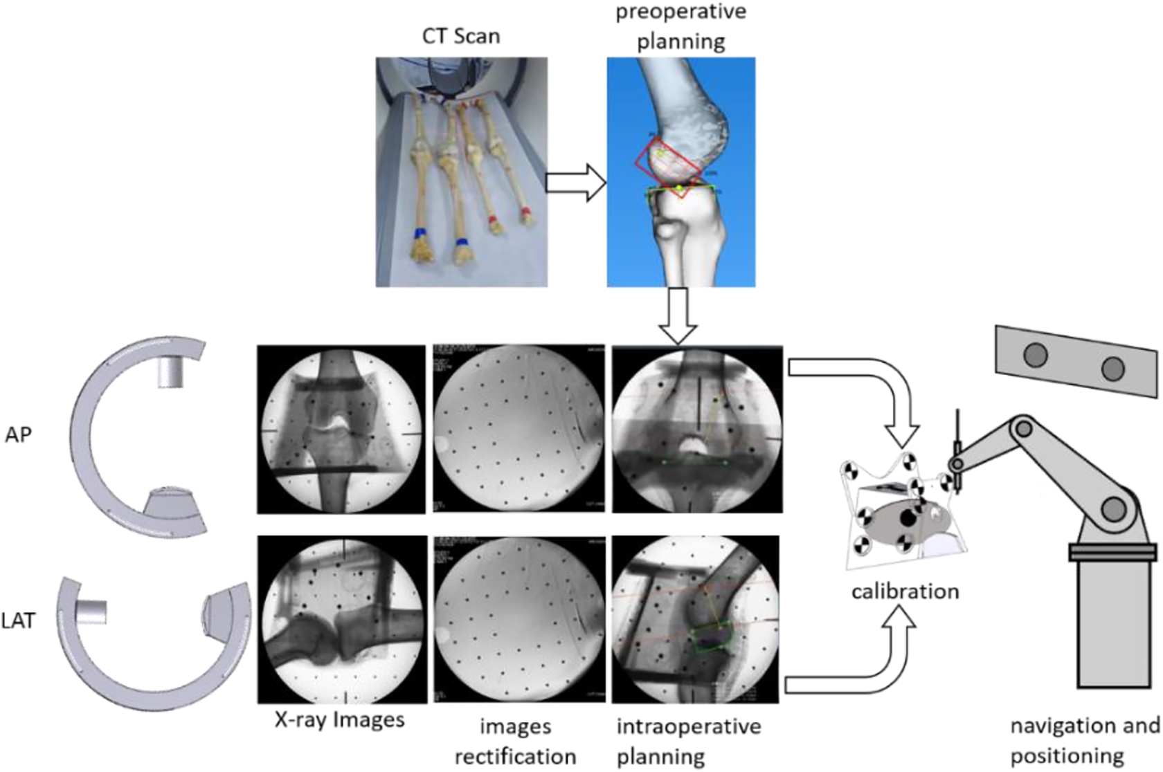
Workflow of navigation.
Results
3-D and 2-D registration experiments
Steel balls were embedded in bone models at the end points of femoral and tibial reconstruction tunnels according to the method in the “Preoperative planning system” section (Figure 9(a)). Preoperative and intraoperative 2-D normalized coordinates of steel balls are calculated by the method in the “Relationship between preoperative CT data and intraoperative X-ray images” section. Differences of preoperative and intraoperative coordinates of steel balls are calculated. X(%) represented the differences in X direction and Y(%) represented the differences in Y direction. Comparison of 3-D and 2-D registration by different users and comparison of 3-D and 2-D registration at different projection directions are conducted to evaluate generalizability of 3-D and 2-D registration method.

3-D and 2-D registration experiments. (a) Bone models and (b) experiment image.
Comparison of 3-D and 2-D registration by different users
Three experimenters conducted ACL path planning in preoperative and intraoperative path planning system, respectively, to evaluate the subjective factors in the registration errors. Tests are conducted under the following steps: Establish preoperative 2-D normalized coordinate systems. 3-D models of bones are reconstructed in preoperative path planning system using CT images. Normalized coordinate systems are established according to the method in the “Relationship between preoperative CT data and intraoperative X-ray images” section at AP and LAT projections, respectively, in preoperative path planning system. Calculate preoperative normalized 2-D coordinates of steel balls are calculated according to equation (1). Establish intraoperative 2-D normalized coordinate systems. Standard X-ray images of the knee joint at AP and LAT projections are captured by a C-arm. Normalized coordinate systems are established according to the method in the “Relationship between preoperative CT data and intraoperative X-ray images” section at AP and LAT projections, respectively, in intraoperative path planning system. Calculate intraoperative normalized 2-D coordinates of steel balls, according to equation (1).
Every experimenter repeated the test 10 times. Figures 10 and 11 are results of comparison of preoperative and intraoperative coordinates of steel balls by three experimenters. All errors are below 3%.

Comparison of planning on X-ray images by different users at AP view. AP: anteroposterior.
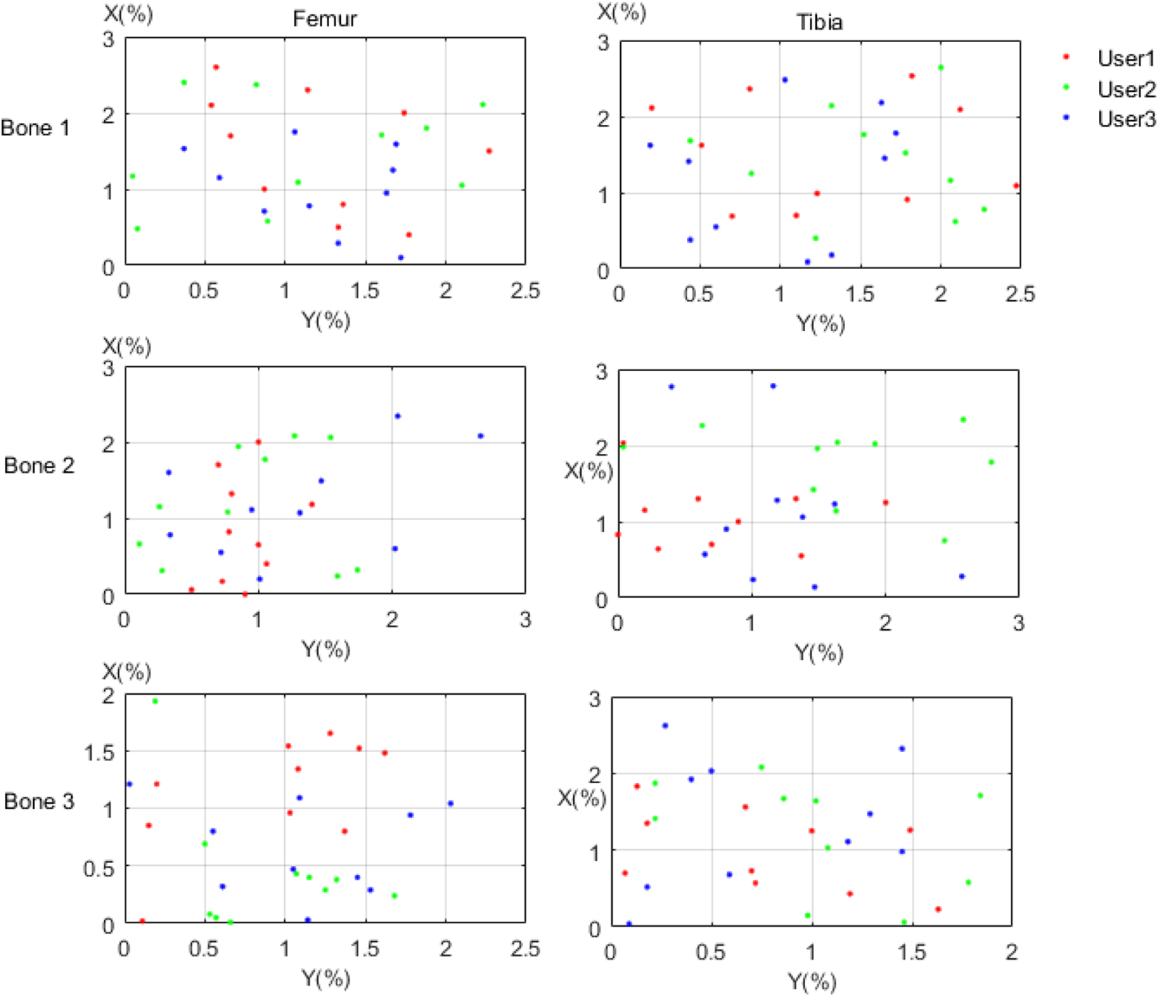
Comparison of planning on X-ray images by different users at LAT view. LAT: lateral.
Comparison of 3-D and 2-D registration at different projection directions
Preoperative ACL path planning is conducted by one tester taking the same first two steps in the “Comparison of 3-D and 2-D registration by different users” section. However, X-ray images are captured through a C-arm at not only standard AP and LAT projections but also unstandard AP and LAT projections. The steps of intraoperative path planning are as follows: Standard X-ray images of the knee joint at AP and LAT projections are captured through a C-arm. X-ray images of the knee joint at AP and LAT projections are captured through a C-arm at unstandard AP and LAT projections with an angle of -3° to standard projections. X-ray images of the knee joint at AP and LAT projections are captured through a C-arm at unstandard AP and LAT projections with an angle of 3° to standard projections. X-ray images of the knee joint at AP and LAT projections are captured through a C-arm at unstandard AP and LAT projections with an angle of 5° to standard projections. Normalized coordinate systems at different projections (−3°, 0°, 3°, 5°) are established according to the method in the “Relationship between preoperative CT data and intraoperative X-ray images” section at AP and LAT projections, respectively. Intraoperative normalized coordinates of steel balls are calculated according to equation (1) at different projections.
Test was repeated 10 times. Figures 12 and 13 are results of comparison of preoperative and intraoperative coordinates of steel balls by one experimenter. All errors are below 5%. The errors increased with the angle of real projection to standard AP and LAT projections in general.

Comparison of planning on X-ray images in different projections at AP view. AP: anteroposterior.
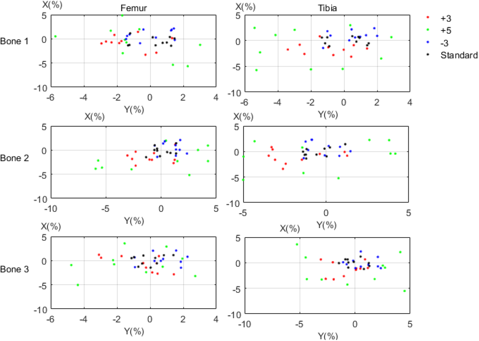
Comparison of planning on X-ray images in different projections at LAT view. LAT: lateral.
Navigation accuracy
Steel balls were embedded in the dry cadaver femur and tibia as the surgical targets. Four pairs of dry cadaver femur and tibia were used to evaluate the position accuracy of navigation system (Figure 14). Table 1 presented that the mean positioning errors of the end points of femur and tibia were 1.78 mm and 1.67 mm, respectively.
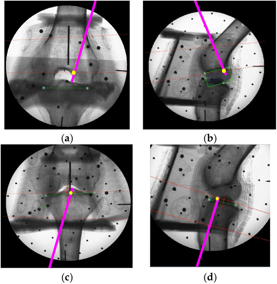
X-ray images of positioning of the tunnels: end points of planning tunnels were marked in yellow circles and positioning tunnel was marked in purple line. (a) Femoral points at AP projection, (b) femoral points at LAT projection, (c) tibial points at AP projection, and (c) tibial points at LAT projection. AP: anteroposterior; LAT: lateral.
Positioning errors of the navigation system for ACL reconstruction.
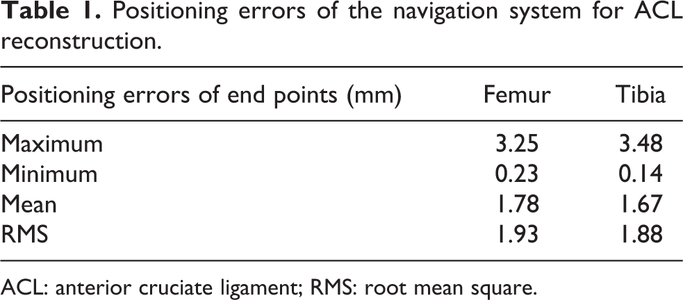
ACL: anterior cruciate ligament; RMS: root mean square.
Cadaver experiments
ACL reconstruction was carried out in two cadavers (Figure 15) using the ACL RRPS. Experiments were conducted according to the workflow in Figure 8. Cadavers were rescanned by CT device after surgeries. Preoperative and postoperative 3-D models of knee joints were registered in Geomagic Studio. The errors between positions of preoperative and postoperative end points of ACL tunnels are defined as the system accuracy. Table 2 presented that the mean positioning errors of the end points were 2.17 mm.

Cadaver experiment.
Positioning errors of cadaver experiments.

Discussion
Clinical anatomy method19 is applied in this article to propose a 3-D and 2-D registration method for ACL reconstruction. Brahmet line and anterior and posterior cortical lines are used to establish 2-D coordinate systems of femur and tibia, respectively. Users have an important role in establishing 2-D coordinates systems, like the decision about the standard projection images or the selection of osseous anatomical landmarks. Comparison of 3-D and 2-D registration by different users is conducted. All errors between preoperative and intraoperative coordinates of steel balls of three experimenters are below 3%. Although subjective factors will have an effect on the planning results of end points of ACL tunnels, the errors of different users vary slightly. As it is difficult to capture the ideal AP and LAT projection views of X-ray images, the effects of the projection views on the registration errors were tested. Comparison of planning on X-ray images in different projections shows that the errors at unstandard AP and LAT projections are larger than that at standard AP and LAT projections, and the errors increase with the angle of real projection to standard AP and LAT projections in general. Although the error is within ±5%, if the projection angle to standard projection is under 5%, it is better to capture X-ray images at standard AP and LAT projections as closely as possible to reduce registration errors.
The ACL RRPS includes a preoperative path planning system, an intraoperative path planning system, and a navigation and positioning system. A new calibrator is applied in this article to improve the accuracy of calibration of C-arm. 24 Two X-ray images are necessary for 3-D and 2-D registration. Compared with point cloud-based systems 9 –12 or 3-D printing-based method, 13 the ACL-RRPS-AC in this article will increase intraoperative radiation. However, in traditional arthroscopic ACL reconstruction, X-ray images are also needful to verify the position of the ACL tunnels. Two more X-ray images are acceptable, considering the positioning accuracy of tunnels with remnants preservation of the cruciate ligaments. Radiation exposure using ACL-RRPS-AC is the same as the traditional intraoperative X-ray image-based systems, 14 but because Quadrant method 15 and Klos method 16 have not taken into account the individual differences of patients, these systems 14 cannot achieve the anatomical location of the end points of ACL reconstruction tunnels. The positioning accuracy of femoral and tibial end points using ACL-RRPS-AC is as follows: 1.78 mm and 1.67 mm in bone modes experiments and 2.15 mm and 2.17 mm in cadaver experiments. Visual tracking errors, criterions of standard AP and LAT view, manual point-selection errors in preoperative and intraoperative images, and other factors may have an influence on the positioning accuracy. The positioning precision of tunnels using ACL-RRPS-AC is not as good as that using point cloud-based systems, 9 –12 which range from 1 mm to 1.5 mm. But it is below 3 mm, which can meet the clinical requirements. 18 And it is much better than the traditional arthroscopic ACL reconstruction, the positioning precision of which is up to 6.2 mm and 6.46 mm. 14 The errors in the “Navigation accuracy” section are different from the result of reference. 24 The methods to get the pixel coordinates of targets in Na et al. 24 and this article having nothing in common. The pixel coordinates of targets in Na et al. 24 are determined by the projections of steel balls in X-ray images, which mean that there is no 3-D and 2-D registration errors in Na et al. 24 However, the pixel coordinates of targets are calculated through 3-D and 2-D registration. Calibration errors of C-arm, 3-D and 2-D registration errors, and visual tracking errors may all result in positioning errors in this article.
The surgery time of ACL reconstruction using ACL-RRPS-AC ranges from 30 min to 40 min. It is about 10–20 min longer than the traditional arthroscopic ACL reconstruction 14 and the point cloud-based systems. 12 However, it could be reduced through improvements in proficiencies of surgeons. 14
Conclusions
To build anatomical tunnels with ACL remnant preserved, this article proposed a robotic positioning system based on AC. Experiments of model bones and cadaver showed that the accuracy of the system is below 3 mm, which meets clinical requirements. Although the positioning accuracy and the surgical time can meet the requirements of ACL reconstruction, the gap between our system and the navigation systems in other surgery like neurosurgery or maxillofacial surgery still exists. In the future, we will focus on intraoperative safety control strategy and improving the precision of the system. On the premise of ensuring safety, the system can be applied in clinic.
Footnotes
Acknowledgment
The authors thank the anonymous reviewers for their constructive remarks and suggestions for improving this article.
Author contributions
Na Guo, Min Wei, Biao Yang, Lei Hu, and Tianmiao Wang discussed the methods; Na Guo wrote the software; Biao Yang, Yuhan Wang, and Hongsheng Liu designed the experiment platform; Na Guo, Min Wei, Biao Yang, Yuhan Wang, Hongsheng Liu, and Guoxin Yu performed the experiments; Na Guo analyzed the data; Na Guo wrote the article; and Min Wei, Tianmiao Wang, and Lei Hu provided the funds support.
Declaration of conflicting interests
The author(s) declared no potential conflicts of interest with respect to the research, authorship, and/or publication of this article.
Funding
The author(s) disclosed receipt of the following financial support for the research, authorship, and/or publication of this article: This research was funded partly by the National Hi-Tech Research and Development Program of China under grant no. 2015AA043204, the National Natural Science Foundation of China under grant no. 61333019, and the Capital Medical Development Research Fund under grant no. 201624094.