
Abstract
Motion accuracy is an important indicator to evaluate the performance of robots. The driven arm of the Delta robot is composed of a pair of parallelogram mechanisms. Because of the errors in components processing and installation, the parallelogram-driven mechanism will tilt. In addition, the load will have greater inertia impact on the end-effector in high-speed working condition. Therefore, the parallelogram-driven mechanism and loading effect will cause the parallelism error of the moving platform and affect motion accuracy of the robot. Aiming at the error analysis and motion accuracy of the Delta robot, currently, most studies mainly consider the influence of dimension error, clearance error, and driving error. There are few research conducted on the kinematics and error analysis considering parallelism error of the mechanism. The purpose of this article is to study the influence of parallelism error on motion accuracy of the robot. Firstly, the space vector method in mathematics is used to calculate the forward solution of the robot, and the kinematic equations of each kinematic chain are established. Secondly, the article analyzes the influence of the non-parallelism of the driven mechanism on motion error of the robot. Taking the D3PM-1000 robot as an example, it is obtained from the simulation results that with the increase in the tilt angle of the moving platform, the motion error caused by parallelism error also increases and the variation value is obvious, especially in the z direction, meaning that the parallelism error has a great influence on the motion error of the mechanism. The article effectively complements the research field of error analysis and provides a theoretical reference for the error compensation of the robot.
Introduction
Delta parallel robots have the advantages of high moving speed, strong bearing capacity, and good dynamic performance. 1 –4 They are widely used in assembly testing, packaging, sorting, precision positioning, and other fields. 5,6 Motion accuracy is the key indicator to evaluate the performance of robots. With the wide application of parallel robots, people have higher and higher accuracy demand. 7,8
Professor Sun Zhili 9 and his team made a thorough study on the error modeling and reliability analysis of the Delta parallel robot, mainly from three aspects: dimension error, clearance error of the joints, and driving error. Ropponen and Arai 10 presented the relation between the joint displacement errors of Stewart platform manipulators and the end-effector accuracy. The position errors of the joints and the actuation errors and backlash are included to the kinematic model. Chebbi et al. 11 studied the 3-UPU parallel robot and constructed a model of the mechanism. The model is presented in an analytical form, which allowed us to predict easily the pose error for a given external load, a nominal pose, and the structural parameters of the 3-UPU parallel manipulator. There are many studies on the error and accuracy of parallel robots that consider joint errors. 12,13 In addition, Cui and Zhu 14 studied the influence of various error sources in the whole workspace, and the error model of the parallel industrial robot was established by Jacobian matrix, then the accuracy analysis was carried out. Chen et al. 15 presented an approach to predict the accuracy performance of the general planar parallel manipulators due to the input uncertainties and the joint clearance. Based on the theory of envelope, a geometric method was employed to uniformly construct the indeterminate influences of these two error sources on the pose (position and orientation) deviation of the manipulators. Xu established the kinematic model of Delta parallel robot and studied the influence of each error source on the kinematic reliability of the mechanism, mainly from the aspect of geometric dimension errors of each component. 16 Zhang Xianmin established an error model considering joint clearance and analyzed the influence of joint clearance on error distribution in repeated positioning. 17 Yongjie Zhao introduced a spatial synthesis method of 3UPS-PRU parallel robot. Considering the constrained dimensions of the installation, the size of the robot, and the rotational angle of the joints, a dimension synthesis method for parallel robot considering the maximum value was proposed. 18
In addition to the above, there is a lot of research on robots. Pavol Bezaka represented a simulated model of a multi-fingered robotic hand for grasping tasks. An intelligent hand-object contact model was developed for a coupled system assuming that the object properties were known. 19 In Pavol Bozek’s paper, the new method of calculation based on the intrinsic properties of the plane was proposed. The stated mathematical calculation was a suitable method for determining the trajectory of mobile robots and industrial robots. 20 In 2018, the article dealt with the research of the supplementation of industrial robot effector trajectory’s control systems by an inertial navigation system. 21 Ivan Kuric’s article dealt with measurement of pose repeatability of industrial robot FANUC LR Mate 200iC (Japan). The measurement methodology was based on the so-called ISO cube placed in the most used part of robot workspace. Individual steps of the solution, the analysis of measurement data, and results were presented in the article. 22
Aiming at the kinematics and error analysis of the Delta parallel robot, currently, most studies mainly consider the influence of dimension error of each component, the joint clearance error, and the influence of the driving angle on the motion output of the robot. There are few research conducted on the kinematics and error analysis considering the degree of non-parallelism of mechanism. In this article, the parallelism error of the moving platform is taken into account, the mathematical model is established. The kinematics analysis of the robot is performed by establishing kinematic equations. Therefore, the influence of parallelism error on the motion accuracy of the robot is obtained. The research complements the kinematics analysis and error modeling of the Delta robot. It is of great significance to the structural optimization and error compensation of the mechanism. 23 –27
The description of the Delta robot and parallelism error
The description of the Delta robot
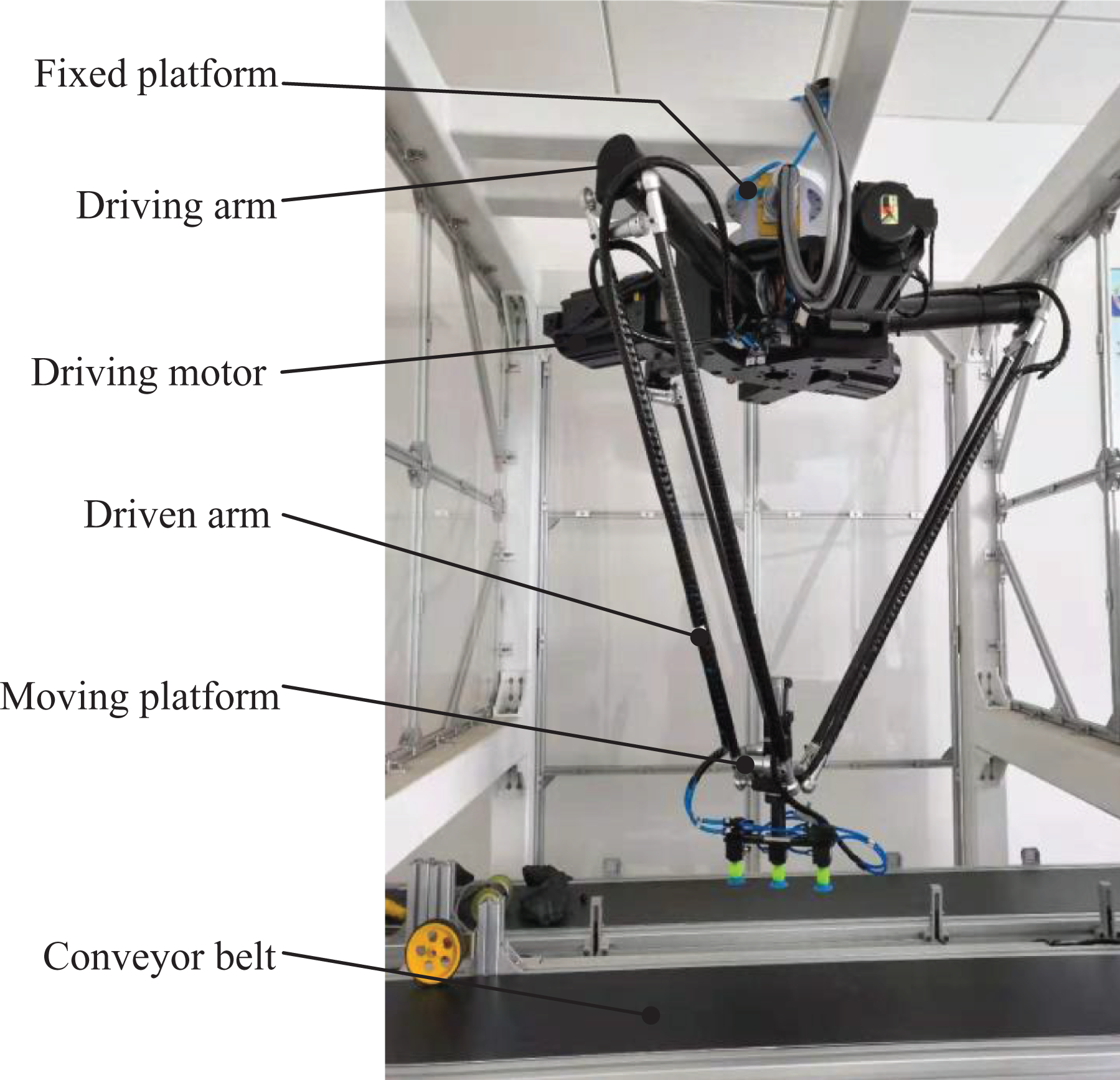
The Delta parallel robot is composed of a fixed platform, a moving platform, and three identical kinematic chains. The three chains are used to connect two platforms, and they are distributed at 120°. Each chain is composed of a driving arm and a driven arm connected by the revolute joint, and the driven arm is composed of a parallelogram mechanism. 28 The structure of the Delta robot is shown in Figure 1.
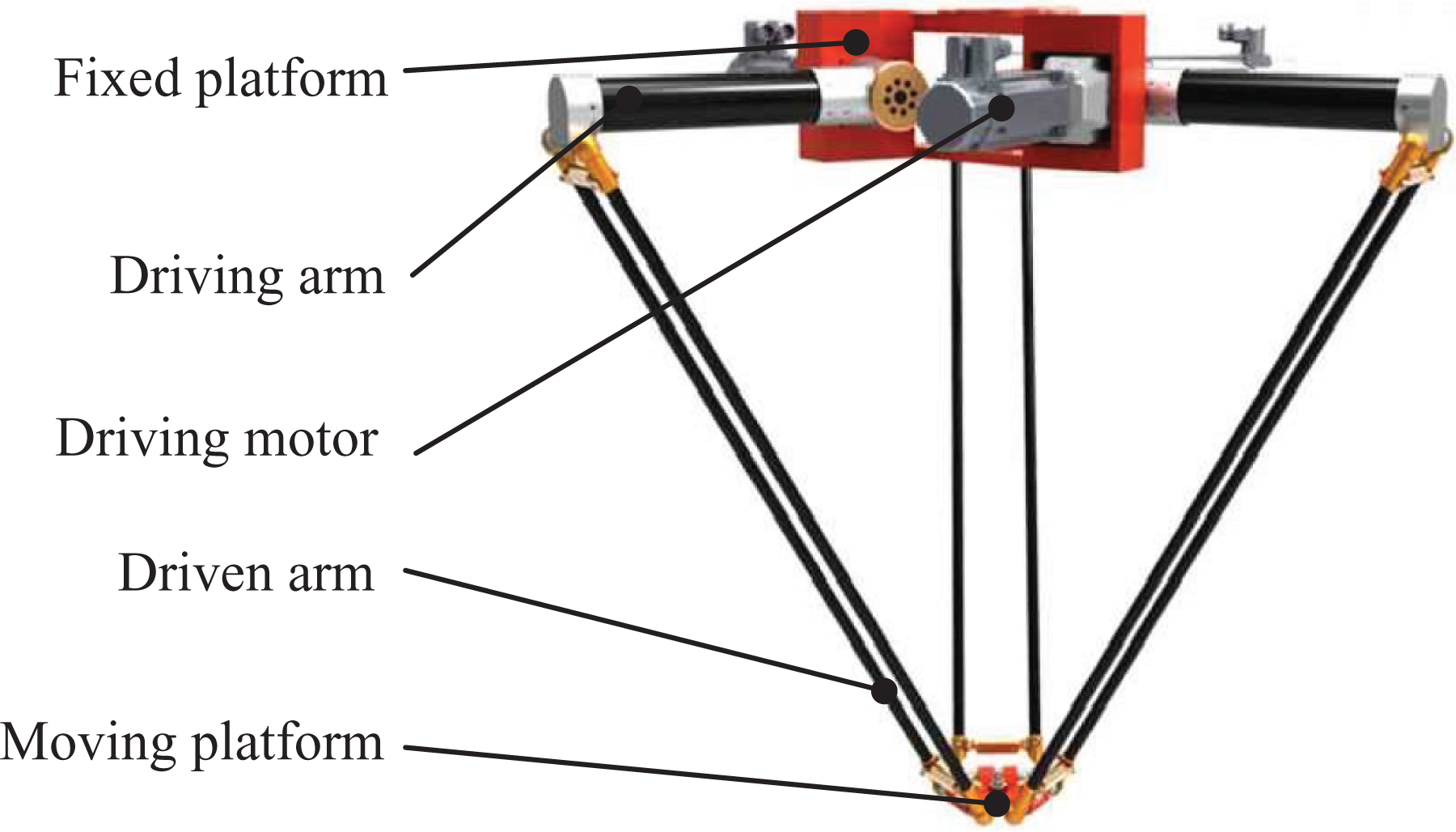
The structure of the robot.
The description of parallelism error
Parallelism describes the degree of parallelism between two planes or lines. 29,30 It refers to the maximum allowable error of a plane (edge) parallel to another plane (edge). Parallelism evaluates the state of parallelism between straight lines, planes, or between straight lines and planes. One line or plane is the evaluation benchmark. The parallelism error between two ideal straight lines or planes is fixed, 31 meaning that the results of parallelism error are same no matter which line or plane is used as the benchmark. In this article, the transverse bar of the parallelogram mechanism is regarded as an ideal straight line and the moving platform is regarded as an ideal plane, namely, the straightness error of the transverse bar and the flatness error of the moving platform are zero.
The driven arm of each chain of the robot is composed of a pair of parallelogram mechanisms. Due to the machining error and installation error of the component, the parallelogram-driven mechanism will not be parallel. In addition, when the Delta robot is running at high speeds, the load will produce greater inertia impact, 32 which will cause the moving platform of the robot not to be parallel to the horizontal plane, resulting in a slight tilt angle. Therefore, the non-parallelism of the parallelogram will lead to the tilt of the moving platform and affect motion accuracy of the robot. The component and plane are regarded as ideal state in this article, and then the kinematic equations and error modeling considering the parallelism error of the mechanism are established.
Kinematic modeling considering parallelism error
The coordinate system of the mechanism
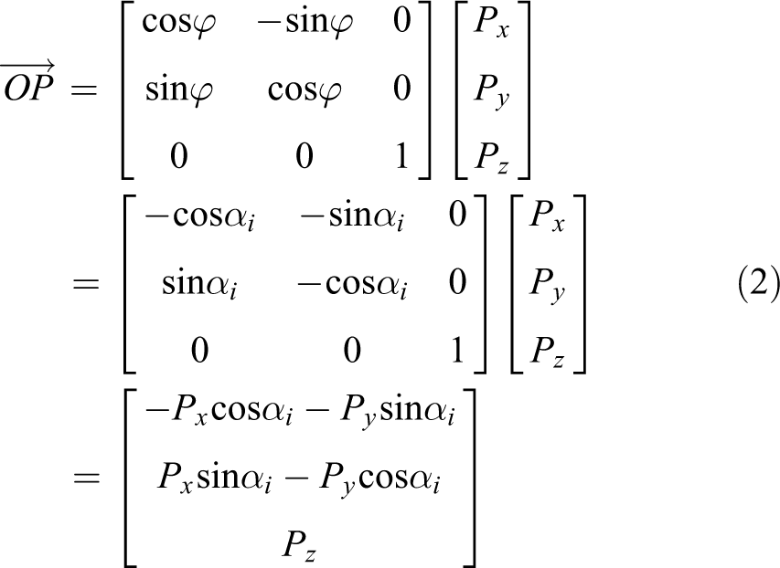
The kinematic chain of the Delta parallel robot is shown in Figure 2. Point O is the center point of the static platform. Point P is the center point of the moving platform.

Motion diagram of kinematic chain.
When considering the non-parallelism of the parallelogram-driven mechanism, the angle between the transverse bar connected to the moving platform and the horizontal direction is β, and the angle between the moving platform and the horizontal plane is γ. The distance between the connecting point (the middle point of the lower transverse bar) and the horizontal line of the platform is h, as shown in Figure 3.

Schematic diagram of tilt angle of the moving platform.
Forward kinematic model of the mechanism
The forward solution is calculated by space vector method. Taking a kinematic chain as an example, according to the geometric method, the closed-loop equation of the ith chain is

Firstly,

The tilt angle of the moving platform in the horizontal direction is γ, so

From the above formulas, it can be obtained as


Then we can get
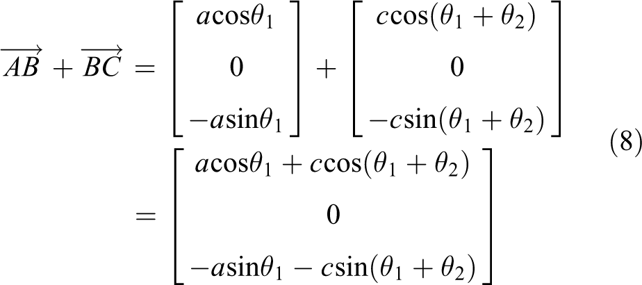
From the above formulas, it can be obtained as

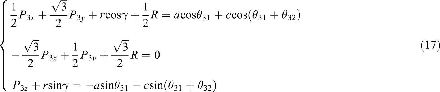
The three equations of kinematic chain can be written as
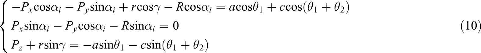
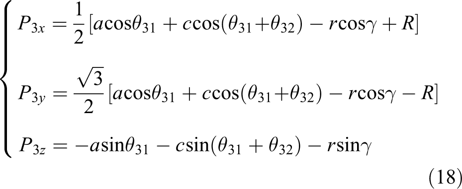
For the first kinematic chain,

It can be obtained as

For the second kinematic chain,

Namely,

It can be obtained as

For the third kinematic chain,

Namely,
It can be obtained as
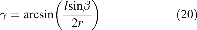
From Figure 3, according to the geometric relationship, it can be concluded that

Because
Therefore, the relationship between the tilt angle of the moving platform and the tilt angle of the parallelogram mechanism is as follows
Motion error analysis considering parallelism error
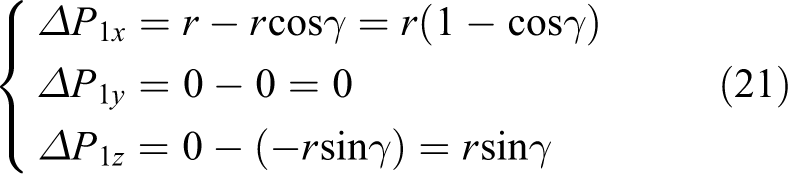
Ideally, the moving platform is parallel to the horizontal plane, namely
For the first kinematic chain, the error value in x, y, and z directions is as follows:
For the second kinematic chain, the error value in x, y, and z directions is as follows

For the third kinematic chain, the error value in x, y, and z directions is as follows

From the above analysis, the position error of the end-effector caused by parallelism error in x, y, and z directions is

In equation (24),
For the first kinematic chain, the error sensitivity coefficient of the parallelism error in x, y, and z directions is as follows

For the second kinematic chain, the error sensitivity coefficient of the parallelism error in x, y, and z directions is as follows

For the third kinematic chain, the error sensitivity coefficient of the parallelism error in x, y, and z directions is as follows:

Numerical example
This article takes the robot of Chen Xing (Tianjin) automation equipment company in our laboratory as an example. The model of this robot is D3PM-1000. It is mainly composed of a fixed platform, moving platform, driving arm, and driven arm. The robot’s workspace covers a diameter of 500–1400 mm, and its grasping speed is 75–150 times per minute. Its maximum acceleration and maximum velocity are 100 m/s2 and 8 m/s, respectively. It has the characteristics of moving in x, y, and z directions and is widely used in the field of high-speed sorting and packaging. The robot is shown in Figure 4.
The diagram of D3PM-1000 robot.
Through the product instruction manual and actual measurement, the structural parameters of this robot are presented in Table 1.
Structural parameters of the robot.

r 1: radius of the fixed platform; r 2: radius of the moving platform; a: the length of the driving arm; c: the length of the driven arm.
The distribution angles of the driving arm are
Since the parallelism error and tilt angle of the robot are small, the range of the tilt angle γ between the moving platform and the horizontal plane can be taken as
The simulation analysis is carried out with MATLAB 2014a. It can be concluded that on three kinematic chains, the relationship in three directions between the motion error caused by the tilt angle γ, and the tilt angle is shown in Figures 5 to 7.

Error curve of the first kinematic chain.

Error curve of the second kinematic chain.

Error curve of the third kinematic chain.
From equation (21), we can get the relationship between the motion error of the first kinematic chain and the tilt angle of the platform.
From equation (22), we can get the relationship between the motion error of the second kinematic chain and the tilt angle of the platform.
From equation (23), we can get the relationship between the motion error of the third kinematic chain and the tilt angle of the platform.
It can be seen from Figures 5 to 7 that with the increase in the tilt angle of the moving platform, the motion error caused by the parallelism error also increases and the variation value is obvious, especially in the z direction, meaning that the parallelism error has a great influence on the motion error of the mechanism. Among these, the influence degree in z direction (i.e. vertical direction) is significantly greater than that in x and y direction (i.e. horizontal direction). Therefore, it is necessary to control the component error of the parallelogram-driven mechanism and reasonably increase the rigidity of the moving platform, thereby effectively reducing the parallelism error and achieving the purpose of improving motion accuracy.
According to the calculation results, it is obtained that
By measurement, the length of the transverse bar is l,
So the relationship between the tilt angle of the moving platform and that of the parallelogram mechanism is shown in Figure 8.

The relationship between the tilt angle of the moving platform and the tilt angle of the parallelogram mechanism.
Figure 8 reflects the relationship between the parallelism error of the moving platform and the non-parallelism of the parallelogram-driven mechanism. As the parallelism error of the driven mechanism increases, the tilt angle of the moving platform also increases. Thus, the motion error of the end-effector is increasing.
From the formula
It can be seen that β decreases with the increase in l, so when the parallelism error caused by the component error is determined, namely the value of h is fixed, the length l of the transverse bar can be increased appropriately to reduce the tilt angle β of the driven mechanism. Moreover, we can also improve motion accuracy by controlling the error of driven components.
Conclusions
In this article, the influence of the non-parallelism of the driven mechanism on the parallelism of the moving platform is analyzed. The kinematic equation and error modeling of the mechanism considering parallelism error are established. The influence of parallelism error on motion error is analyzed. The simulation results show that the parallelism error has a great influence on motion accuracy of the robot, especially in the z direction. When studying the motion error of parallel mechanisms that are similar to Delta robots, it is necessary to consider the parallelism error. The results of this article can be applied to other high-speed and high-precision mechanisms, such as high-speed parallel machine tools. To improve the manufacturing precision, the influence of parallelism error should be considered and controlled. The research complements the motion error analysis and provides a theoretical basis for the high-precision calibration and error compensation of robots. Besides, what factors can cause non-parallelism and how these factors affect motion accuracy of motion are my next research work.
Footnotes
Declaration of conflicting interests
The author(s) declared no potential conflicts of interest with respect to the research, authorship, and/or publication of this article.
Funding
The author(s) disclosed receipt of the following financial support for the research, authorship, and/or publication of this article: This research was funded by the National Natural Science Foundation of China (Science Foundation) [nos 51834006 and 11802035] and the Fundamental Research Funds for the Central Universities [nos 2019QJ002 and 2011YJ01].