
Abstract
To improve automobile travel safety and relieve the intension of driving fatigue, a synergetic strategy on the throttle and brake combined control of automobile cruise system is proposed based on fuzzy control theory. A hierarchical control structure, including the upper fuzzy controller and the lower model match controller, is designed for integrated control function. The upper controller consists of the two input variables, that is, the deviation of the theoretical safe distance and the relative distance and the relative velocity between the host car and the preceding vehicle, and the single output variable, that is, the excepted acceleration of host car. The lower controller has achieved the fast compensation of excepted acceleration by adopting parallel feedforward and feedback compensator to input into the inverse dynamics model of automobile cruise system. Using MATLAB/Simulink, the control function on the proposed synergetic strategy is validated for different working cases. The results show that the synergetic strategy possesses an integrated capability involved automated stop & go control, and following the preceding car to prevent rear-end collision, and the constant velocity cruise whether the driving conditions of the city road or expressway.
Keywords
Introduction
Recently, with the rapid growth of vehicles’ number in the world, traffic jams and accident rate continue to rise in every major city of the world that townspeople’s travel environment and life safety are influenced seriously. As an intelligent vehicle technology, the advanced driver assistance systems has attracted widespread attention of many scholars and consumers and has achieved rapid development because it has to enhance the driving safety and add convenience for the driver by providing a great valuable information or by assisting with longitudinal and lateral control, such as the forward collision warning (FCW) system, 1,2 lane departure warning system, 3,4 adaptive cruise control (ACC)system, 5,6 and intelligent vehicle navigation system 7 .
It was also known that the ACC system, as driver assistance systems, can adjust the host car’s velocity to keep a safe distance with the preceding car through obtaining the lidar’s or radar’s information. So, the system can relieve driver’s fatigue to some extent. But, the ACC systems are mainly used in highway driving condition when the velocity is over 40 km/h, and it does not suit for city traffic environment with the high density and the slow velocity. It is worth mentioning that Stop & Go systems are applied to deal with the city traffic condition when the velocity is less than 40 km/h. 8 –10 It can realize vehicle’s stationary control at low velocity and follow actively the preceding car. So, the system is better for the city traffic environment, especially the traffic congestion or the stop–go condition. Therefore, it is necessary to develop an intelligent cruise system to integrate various control functions because it will improve greatly the defect of control function adopting single system. The integrated capability research on multi-system, such as, the FCW, ACC system with the Stop & Go function hasn’t been realized until now on complex driving conditions.
In the last few years, there were a large amount of literature in ACC systems aimed to highways. Zhao et al. proposed a novel supervised actor-critic (SAC) strategy for adaptive cruise control problem adopting feedforward neural networks and demonstrated the stability and feasibility of the SAC algorithm by several driving scenarios. 11 Lee et al. proposed an adaptive cruise control system with a longitudinal controller that follows a preceding vehicle in autonomous vehicles, and the controller is simulated with CARSIM 8.0 and MATLAB/Simulink R2013b. 12 Horiguchi and Oguchi have put forward a car-following model that simulates three types of ACC behaviors which retain distance gap, time gap, and time headway for a microscopic traffic simulator to evaluate the impact of ACC penetration on highway traffic conditions. 13 Wang et al. proposed an improved cooperative adaptive cruise control (CACC) algorithm based on the sliding mode control theory and analyzed the range of CACC controller parameters to maintain string stability even if inter-vehicle communication is partially invalid and simulate the CACC algorithm in MATLAB/Simulink. 14 Omae et al. proposed the control procedures and inter-vehicle communication schemes required for CACC of heavy-duty vehicles and validated the proposed procedures by simulation and experiments. 15 Zhao et al. present a novel spacing control law for ACC vehicles to perform spacing control mode based on model predictive control. A real-time weight tuning strategy is proposed to solve time-varying multi-objective control problems, and the performance on spacing control law of ACC system is simulated by MatLab/Simulink combined with the CARSIM-based vehicle model. 16
A control strategy that integrates multisystem functions into one would be needed to research or explore. Fuzzy logic control strategy has been considered as one of the powerful tools for achieving the control goal of ACC system because it does not rely on an accurate mathematical model, and it represents the human reasoning method in a very effective way and it is suitable for dealing with nonlinear and uncertainty control system. 17 –20 Yu et al. have put forward an error compensation mechanism to eliminate the filtering error for uncertain nonlinear system by designed command filtering based on adaptive fuzzy approach. 21,22 Wang et al. have put forward an adaptive fuzzy control scheme to overcome the problem on the unknown direction hysteresis for a pure-feedback nonlinear system adopting the backstepping technique. 23,24 Wang et al. have put forward an adaptive fuzzy tracking controller to converge the tracking error to an arbitrarily small neighborhood of the origin for closed-loop nonlinear time-delay system. 25 –27 Liu et al. proposed an integrated fuzzy controller to guarantee the system uniform ultimate boundedness for a pure-feedback nonlinear system with a fuzzy dead zone. 28,29 Zhou and colleagues proposed an adaptive control approach to solve the problem on input saturation and output constraint for a class of nonlinear systems by combining the backstepping technique and dynamic surface control methods. 30 –33 Naranjo et al. proposed a fuzzy control strategy that considered the synthetic control of accelerator and brake based on 13 fuzzy rules, and a test showed that the unmanned vehicles like human-driven vehicles adapt to any kind of condition in a great scope of velocity. 34 Tsai et al. proposed a fuzzy longitudinal control system with car-following behavior and validated the main functions of ACC and stop-and-go control. Milanés et al. describe a comparative study of two intelligent control techniques, that is, fuzzy and intelligent proportional–integral control to try to solve the stop-and-go control in urban environments at very low speeds. 35
Although ACC system has been relatively fully developed, but in some ways, it needs to be improved, for example, a further study on intelligent cruise control algorithm, especially the integration of ACC system and Stop & Go systems suited to complex traffic environment and the further developing of integrated system product.
It is our goal to propose a synergetic strategy on the throttle and brake combined control of automobile intelligent cruise system with an integrated control function based on fuzzy theory adopting a hierarchical structure.
The article is structured as follows. The “Synergetic strategy of automobile intelligent cruise system” section describes a synergetic strategy and the control procedure on the throttle and brake combined control of automobile cruise system based on a hierarchical structure. The “The dynamic model of intelligent cruise system” section has set an inverse longitudinal dynamic model of the cruise system. The “Hierarchical controller design” section discusses the design of the upper fuzzy controller and the lower model match controller. The simulation results are presented in the “Simulation results” section and concluding remarks are given in “Conclusion” section.
Synergetic strategy of automobile intelligent cruise system
Figure 1 describes a synergetic strategy on the throttle and brake combined control of automobile cruise system based on a hierarchical structure.
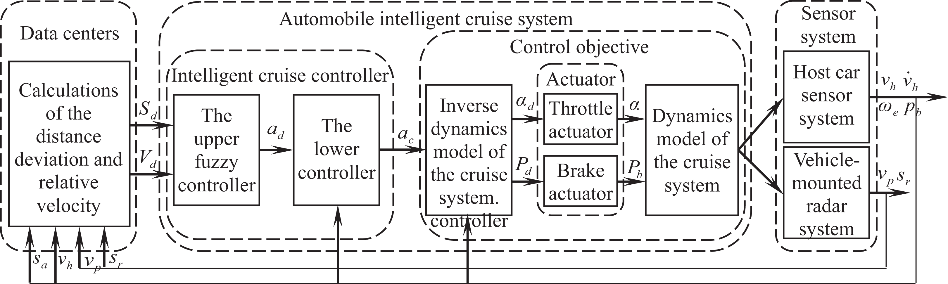
The overall control scheme of automobile cruise system based on a hierarchical structure.
As shown in Figure 1, the overall scheme consists of three parts: data centers are responsible for the data calculation, the intelligent cruise system includes two controllers and control objective, and the sensor system is responsible for the sensor information’s transmit. In Figure 1, the intelligent cruise controller consists of the upper fuzzy controller and the lower model match controller. The input variable of the upper fuzzy controller is the deviation of the theoretical safe distance sa and relative distance sr and the deviation of the preceding car’s velocity vp and the host car’s velocity vh, that is, Sd = sa − sr and Vd = vp − vh, where sa can be obtained by following expression,
Figure 2 shows a control process on the intelligent cruise system. In Figure 2, there are two patterns to calculate the distance deviation, Sd. For the first pattern, namely the CCS mode, the relative distance sr is supposed to be 100 m if there was no preceding car in front of the host car. For the second pattern, namely the intelligent following mode, the theoretical safe distance sa is regarded as the minimum derived from the product of the total time as mentioned previously and the velocity vh from the host car or the setting cruise velocity Vs. Ultimately, the indexes on the actual velocity (vh) and acceleration of the host car, the engineer’s rotate speed, and so on, are obtained and fed back to the data center by the host car sensor and vehicle-mounted scanning laser radar.

Sketch map of the control process on the intelligent cruise control.
The dynamic model of intelligent cruise system
The longitudinal dynamic model of the cruise system
Figure 3 shows the structural components of the longitudinal dynamic model of the cruise system.

Structure component of the longitudinal dynamic model of cruise system.
As can be seen from Figure 3, the model mainly includes the electronic control engineer module, hydraulic torque converter module, automatic mechanical transmission module, vehicle driving system module, and vehicle braking system module. The relationship of modules above is built by the torque and rotate speed, and the model process can be searched by previous works. 36
The inverse longitudinal dynamic model of the cruise system
We know from the “Synergetic strategy of automobile intelligent cruise system” section that the role of setting the inverse longitudinal dynamic model of the cruise system is to obtain the expected throttle opening and braking force according to the expected acceleration. Therefore, the inverse model consists mainly of the inverse engineer model, the inverse brake actuator model, and the switch relationship model between the engineer torque control and brake torque control.
Switch relationship model between the engineer torque and brake torque control
It was also known that a car can increase or decrease the throttle opening to adjust the driving velocity if it wants to realize to accelerate or decelerate. But if the car needs to decrease quickly, it could not meet the need only by decreasing the throttle opening. At this point, it is necessary to get to work for the brake system, while the throttle opening value is zero. Sure, when the car needs not to decrease quickly, it could reach the velocity adjustment only by decreasing the throttle opening. Then, how to realize the deceleration requirement by reducing the throttle opening value or triggering the brake actuator? To resolve the problem above, a maximum deceleration curve is obtained under different velocity conditions by setting simultaneously the value of the throttle opening and brake pressure as zero through repeated tests.
Figure 4 shows a control region adopting the engineer torque control pattern or the brake torque control pattern.

The control region adopting the engineer torque or brake torque control pattern.
To improve the vehicle’s driving stability and avoid the switch frequently between the throttle and brake actuator, a buffer (Δh = ±0.1 m/s2) is set as shown in Figure 4. If the expected acceleration (ad) obtained by the upper fuzzy controller is below the lower limit of the buffer, then the brake torque control pattern (i.e. the brake control) is actuated, that is, the brake was needed to work for reducing quickly the driving velocity. Instead, when the expected acceleration exceeds the upper limit of buffer, then the engineer torque control pattern (i.e. the throttle opening control) is actuated, that is, the throttle actuator was needed to work for increasing quickly the driving velocity. The logic switch between the throttle and brake actuator is expressed as follows

Inverse engineer model
If the engineer torque control pattern is adopted, then the inverse engineer model needs to be set up for obtaining an expected throttle opening according to the expected acceleration of the host car.
Ignoring quality conversion of vehicle rotating parts, the vehicle’s equation of motion is described as follows

where M represents the whole vehicle mass, Fd denotes the driving force, Fb is the brake force, and Ff(v) represents the total of rolling resistance, wind resistance, and so on.
Suppose the elastic deformation on the tire and transmission system need not be taken into account, and then the driving force can be expressed as shown in formula (3)

where ηt denotes a factor of transmission system efficiency. τ is a torque coefficient of the hydraulic torque converter. wt and we represent the rotation rate of the turbine and engineer, respectively. Te is the engineer torque. ig and i0 represent the transmission ratio of the gearbox and the reduction ratio of the final drive. rr denotes the equivalent wheel rolling radius. vh denotes the velocity of host car. So, the factor kd is expressed as follows, kd = (ηt·τ(vh·ig·i0/rrwe)·ig·i0)/rr.
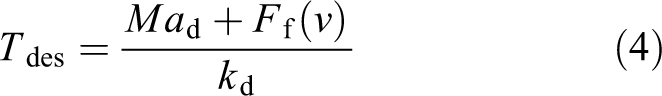
Combining equation (1) and formula (3), the expected engineer torque can be expressed as shown in equation (4)
According to the expected engineer’s torque and rotation speed, the expected throttle opening would be derived by the inverse engineer model, which is listed as the equation.5.

Figure 5 shows the characteristic curve of the inverse engineer torque. By the data of the characteristic curve the expected throttle opening can be found and invoked.

The characteristic curve of inverse engineer torque.
Inverse brake model
As described in the “Switch relationship model between the engineer torque and brake torque control” section, if the brake torque control pattern is adopted, then the inverse brake model needs to be set up for obtaining an expected brake pressure according to the expected deceleration of the host car. Then, the inverse brake model can be expressed as shown in equation (6)
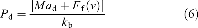
where kb is the proportionality coefficient for brake system and Pd denotes the expected pressure of brake master cylinder when brake pedal is pushed.
Hierarchical controller designs
The upper fuzzy controller
The upper controller is designed to acquire an expected acceleration used for the lower controller according to the change of the relative distance and relative velocity between the host car and the preceding car based on fuzzy control theory.
Fuzzification of input and output variable
The upper fuzzy controller consists of the two input variables, the deviation of the theoretical safe distance (sa) and relative distance (sr) and the relative velocity (vp − vh) between the host car and the preceding vehicle, and the single output variable ad, that is, the excepted acceleration of host car.
These input and output variables of the upper controller are transferred into five fuzzy language variables, including Negative Big (NB), Negative Middle (NM), Zero (ZE), Positive Middle (PM), and Positive Big (PB). The alterable domain range for the Sd, Vd, and ad is, respectively, the interval value from −35 to 35, −120 to 120 (kv=0.5), and −10 to 10. Of course, the alterable domain range is adjustable according to the actual condition. For these input and output variables of the upper controller, the membership functions are shown in Figures 6 to 8.
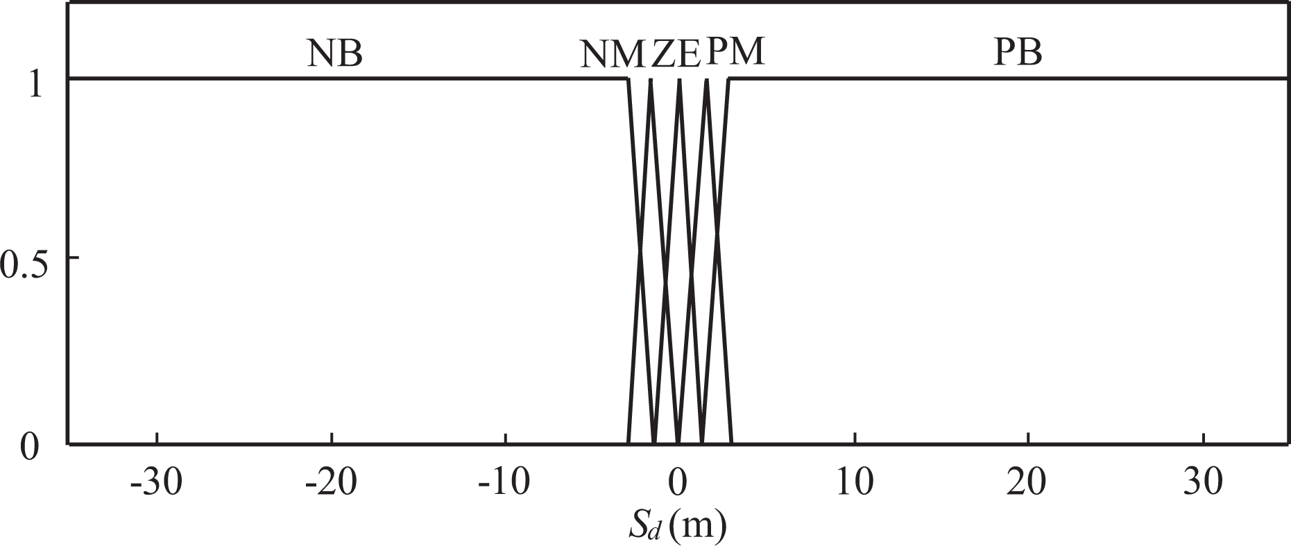
Membership function of the relative distance Sd.
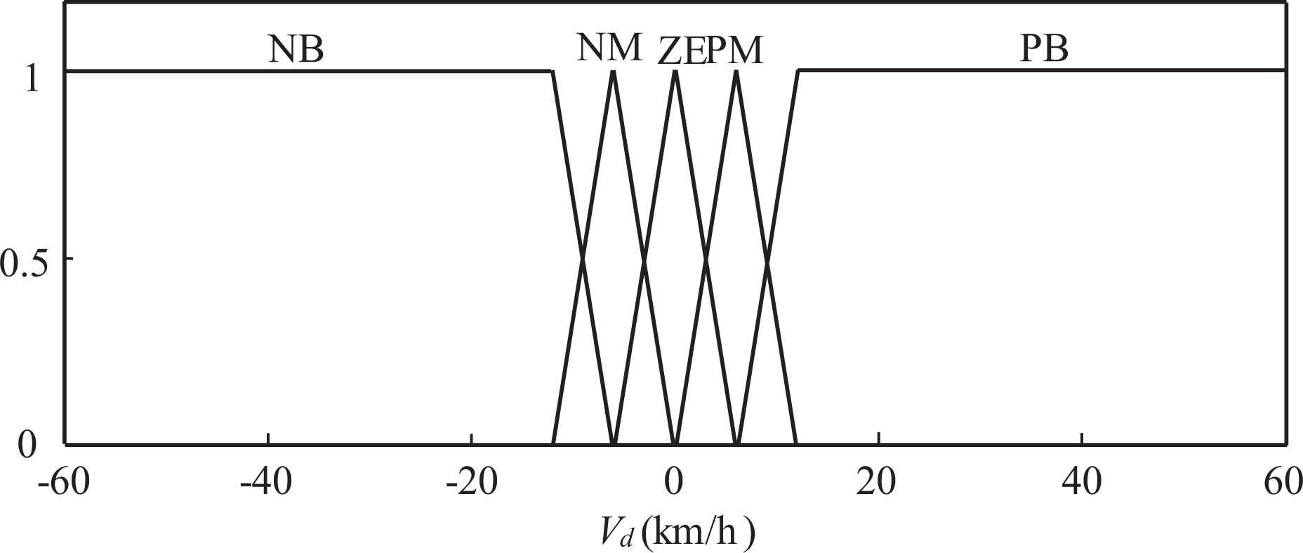
Membership function of the relative velocity (Vd).

Membership function of output variable ad.
Construct rule base
It is generally known that the fuzzy rule base accumulates a vast special knowledge and experience,
37
thereby there include 25 simple control rules in the upper fuzzy controller as presented in Table 1. The fuzzy control rules are characterized by If–Then statements for designed fuzzy linguistic variables. For example, the generic form of the MISO is described as follows.

Fuzzy control rule.

NB: Negative Big; NM: Negative Middle; ZE: Zero; PM: Positive Middle; PB: Positive Big.
In Table 1, if the distance deviation (Sd) chooses NB and the velocity deviation (Vd) chooses NB, then the output variable ades should choose ZE. This rule indicates that the host car is fast approaching the preceding car but the actual distance between two vehicles is very far, then the host car does not need to speed up. Also, if the distance deviation (Sd) chooses PB and the velocity deviation (Vd) chooses NB, then the output variable ad should choose NB. This rule indicates that the host car is rapidly approaching the preceding car and the actual distance between two cars is very close, then it is necessary to decelerate quickly because of the host car tries to avoid rear-ends collision. Similarly, other fuzzy rules are easy to understand as well based on the real condition.
Defuzzification
The defuzzifier is used to convert the fuzzy output to a non-fuzzy decision or control action from inferred fuzzy language by fuzzy inference generator. The method on the center of gravity is adopted to calculate the defuzzifier output as follows,
The lower model match controller
The function of designed lower model match controller is to realize quickly the expected acceleration for the inverse longitudinal dynamic of intelligent cruise system and to guarantee the error between the expected value and the actual control acceleration as small as possible under the conditions of the system structure parameter or driving environment has been changed.
Figure 9 shows the structure composition of the lower model match controller, which consists of three parts, the gauge model, the feedforward compensator, and the feedback compensator.

Structure composition of the lower controller. ac represents the actual control acceleration of the lower controller. ah denotes the deduced expected acceleration by the gauge model.
Dynamics model transfer function
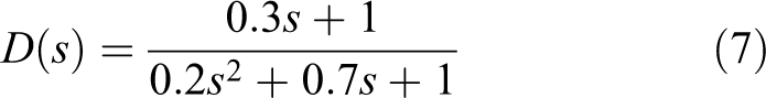
Based on the established cruise system dynamics model, a sinusoidal signal with different frequencies is adopted as the system input, and then the relationships on transfer function between the input and output signal are obtained as shown in formula (7)
Feed-forward compensator
The role of feedforward compensator is to realize the expected acceleration quickly and accurately in the range of the errors permitted. In designing the model, a gauge first-order model is selected considering the standardization of the response. The model of the feedforward compensator, F(s), the first-order gauge model, GM(s), and the dynamics’ transfer function model, D(s) have the following relations as shown in formula (8)

where GM(s) = 1/(s+1). The first-order gauge model, GM(s), is selected for reducing the order of the feedforward compensator.
Feedback compensator
Based on the concept of literature on collision avoidance control, the feedback compensator is designed. Figure 11 shows a lower control system structure considering the effect of model error on cruise dynamics system, Δd, and external disturbance, Ed.

Lower control system structure with model error and external disturbance. ah denotes the deduced expected acceleration by the gauge model. The e represents a control error between the deduced acceleration ah and the actual acceleration of host car

Structure parameters of the lower controller.
The aim of feedback compensator is to eliminate the model error and external disturbance influence on control effect and to avoid any actual acceleration mutation resulted from large amount of feedback. From Figure 10, it can be learned that the transfer function (i.e. the sensitivity function of feedback system), EV(S), from Ed to

The transfer function, HV(S), from ah to

If there is a model error, the above formula would be changed into the following form

The transfer function, EU(S), from Ed to u can be represented as formula (12)

Based on H∞ control theory, the designed condition of feedback compensator should be satisfied for assured feedback system’s stability as shown in formula (13).

where ωe(s) is a weighting coefficient of the sensitivity function of feedback system, ωe(s) = (as + b)/s (a = 0.1, b = 1.15). ωu(s) denotes a weighting coefficient of feedback compensator control variable, ωu(s) = (cs + d)/(s + k) (c = 1, d = k). ωd(s) represents a weighting coefficient of the model error, ωd(s) = (ms + n)/(ps + q) (m = 5.2, n = 5, p = 2, q = 10).
Based on the above analysis, the H∞ transfer function on feedback compensator is given as shown in formula (14)

Therefore, the structure parameters of the lower controller in Figure 9 are given as shown in Figure 11.
The actuator model
The actuator model consists of the throttle actuator and brake actuator linked to two parts, the inverse dynamic model and the dynamic model of the cruise system, as shown in Figure 1. The input variables of actuator are the expected throttle opening and the expected brake pressure, respectively. The actual throttle opening and brake pressure are the output variables of the actuator.
The throttle opening actuator model is expressed as follows

where the throttle opening actuator is considered to be a second-order oscillation system. αd and α represent the expected throttle opening and the actual opening. τ1 and τ2 represent the oscillation coefficient (τ1 = 0.01, τ2 = 0.1).
The brake actuator model is expressed as shown in formula (16)

where the brake actuator is considered to be a first-order inert system. Pd and Pb represent the expected brake pressure and the actual output pressure. λ denotes the coefficient of the first-order inert system (λ = 0.1).
Simulation results
Some typical cases, such as the automatic stop, the complex following case with automatic stop-and-go, automatic acceleration and deceleration adjustment, and the constant velocity cruise case, are given for examining the feasibility and effectiveness of proposed synergetic strategy on the throttle and brake combined control of automobile cruise system adopting MATLAB/Simulink.
Simulation results of various cases
Case 1: The automatic stop case
When the host car drives at 20 km/h, a low-velocity moving vehicle began to slow to stop in front of the host car about 15m after driving for 5 s. Eventually, the host car follows preceding car and automatic stop.
As can be seen from Figure 12, the actual distance sr between the two vehicles is more than the theoretical safety distance sa (see Figure 12(b)), and the host car’s velocity vh is greater than the preceding car’s velocity vp (see Figure 12(a)). At the initiative time, the throttle has a little change owing to the actual distance (sr) is more than the theoretical value (see Figure 12(c)). Soon, the brake pressure begins to increase to reduce the host car’s velocity when the distance sr is near to the distance sa. Then, the host car adjusts repeatedly the brake pressure to reach stability for reducing own velocity until to stop in the range of stopping distance 2 m (see Figure 12(a), (b), and (d)). The results show that the strategy possesses the automatic stop function.

Simulation result of the automatic stop case: (a) velocity following result between the two vehicles, (b) the changing curve of distance between the two vehicles, (c) the changing curve on throttle opening of the host car, and (d) the changing curve on brake pressure of the host car.
Case 2: The complex following case
Under the complex following condition, a preceding car drives at 20 km/h about 80 m in front of the host car with a velocity about 80 km/h. Later, the preceding car began to increase own velocity every 50 s until to 120 km/h, and then it starts to reduce velocity until to zero, and it again begin to start and accelerate until the velocity of 20 km/h.
Figure 13 shows the simulation result of the complex following case 2. Figure 13(a) shows that the host car takes braking action quickly to reduce its own speed to 0 km/h avoiding rear-end collision at starting moment (see Figure 13(a) and (d)). Although the actual distance sr is slightly larger than the theoretical safe distance, it is still a dangerous case because of the speed difference between the host and preceding car is very large, as shown in Figure 13(a) and (b). Later, the host car has realized the following behavior with the change of preceding car velocity, that is, the host car has the ability to realize the acceleration and deceleration adjustment, automatically stops and goes again. From Figure 13(b), it is evident that the host car always keeps the actual distance (sr) near the theoretical safety distance (sa) during the whole follow process.

Simulation result of the complex following case: (a) velocity following result between the two vehicles, (b) the changing curve of distance between the two vehicles, (c) the changing curve on throttle opening of the host car, and (d) the changing curve on brake pressure of the host car.
Case 3: The emergency following case with high speed
The host car found suddenly a car is driving at 20 km/h ahead about 140 m when it drives at 120 km/h. Then, the preceding car began to decelerate until to stop after 60 s, and then it starts again to accelerate until to 18 km/h.
Figure 14 shows the simulation result of the emergency following case 3. From Figure 14, it is evident that the brake pressure of the host car increases quickly, which realizes the rapid decline of host car’s velocity for avoiding urgently rear-end collision even though the actual distance is slightly larger than the theoretical safe distance. Later, the host car has realized the following behavior, such as the deceleration adjustment, automatically stops and goes again.

Simulation result of the emergency following case: (a) velocity following result between the two vehicles, (b) the changing curve of distance between the two vehicles, (c) the changing curve on throttle opening of the host car, and (d) the changing curve on brake pressure of the host car.
Case 4: The setting constant velocity cruise case
Under the constant velocity cruise condition, the host car drives at 120 kms/h. The setting velocity changes from 20 km/h at the initiative time to the different value every 50 s several times.
Figure 15 shows the comparison result of velocity matching and the change of the throttle opening, adopting the tested CCS system based on the proposed synergetic strategy. As can be seen from Figure 15(a) and (c), the host car begin to decelerate owing to the setting value is less than the host velocity at the initiative time and reach immediately the setting velocity. You can see from Figure 15 that the velocity of the host car is perfect to adapt the presetting value both the low and high velocity and that illustrates the strategy can meet requirement of the setting constant velocity cruise function.

Simulation result of the constant velocity cruise case: (a) compared result between the host car’s velocity and setting velocity, (b) the changing curve on throttle opening of the host car, and (c) the changing curve on brake pressure of the host car.
Case 5: The complex case with the setting constant velocity cruise and following case
At the beginning, the host car drives at 30 km/h, and the cruise velocity has been set to 100 km/h. After 30 s, a car has driven abruptly into the lane of host car at 80 km/h and again left this way 50 s later.
Figure 16 shows the simulation result of the complex case with the constant velocity cruise and following case 5. As can be seen from Figure 16, the host car increases velocity quickly to the setting value (100 km/h). Owing to the emergence of preceding car after 30 s, the current pattern of fixed cruise has been changed automatically to the intelligent following mode accompanied by deceleration of the host car to prevent collision accident (see Figure 16(a), (c), and (d)). When the preceding car pulled out of the lane of host car 50 s later, the pattern of fixed cruise has been returned again to keep the velocity of host car at 100 km/h. In the following mode, the host car always keeps the actual distance (sr) near the theoretical safety distance (sa; see Figure 16(b)).

Simulation results of fixed cruise and intelligent following complex case with high speed: (a) compared result between the host car’s velocity and setting velocity, (b) the simulation result of changing distance curve, (c) the changing curve on throttle opening of the host car, and (d) the changing curve on brake pressure of the host car.
Stability analysis of the system response on the lower model match controller
Figure 17 shows the rest result of system response of a following case on low speed without the lower model match controller. As can be seen from Figure 17(a), there are fluctuations in the simulation result of host car velocity compared with the result in Figure 18(a) with the lower model match controller. Furthermore, there are evident flutter and instability in the simulation result of Figure 17(b) on the actual acceleration result of host car compared with the result in Figure 18(a) as well. Besides, you can see from Figure 18(c) that this trend on simulation result of the actual acceleration was in agreement with expected acceleration and stability adopting the lower model match controller. For other cases, the above simulation results still stand. According to the stability analysis of system response, we can conclude that the system will not work steadily if there is no lower model match controller.

Simulation results of a case without the lower model match controller: (a) velocity follow result between the two vehicles and (b) the actual acceleration result of host car.

Simulation results of a case with the lower model match controller: (a) velocity following result between the two vehicles, (b) the actual acceleration result of host car, and (c) compared result between the expected and actual acceleration match controller.
Conclusions
A novel synergetic strategy scheme and the control procedure on the throttle and brake combined control of automobile cruise system have been presented based on a hierarchical structure.
An inverse longitudinal dynamic model, including the switch relationship model between the engineer torque and brake torque control, inverse engineer model, and brake model of intelligent cruise system, have been set up to obtain the expected throttle opening and brake pressure.
Based on the fuzzy control theory, an upper fuzzy controller is designed for acquiring an expected acceleration and a lower model match controller is presented for the fast compensation of excepted acceleration by adopting parallel feedforward and feedback compensator. In the latter part of the article, the stability of system response is analyzed on the lower model match controller.
Using MATLAB/Simulink, some typical cases, such as the automatic stop, the complex following case with automatic stop-and-go, automatic acceleration and deceleration adjustment, the emergency follow case with high speed, and the constant velocity cruise case, are given to realize the function validation on the feasibility and effectiveness of proposed synergetic strategy. Results show that the synergetic strategy possesses the above integrated capability to prevent emergency rear-end collision.
In a word, the research results can offer the theory and technology reference for improving the performances and setting dSPACE type of automobile cruise system.
Footnotes
Declaration of conflicting interests
The author(s) declared no potential conflicts of interest with respect to the research, authorship, and/or publication of this article.
Funding
The author(s) disclosed receipt of the following financial support for the research, authorship, and/or publication of this article: This work was supported, in part, by the Natural Science Foundation of China under grants 61473139 and 61622303, the Natural Science Foundation of Liaoning Province of China (2019-MS-168), and the project for Distinguished Professor of Liaoning Province.