
Abstract
The lower limb exoskeleton is a wearable device for assisting medical rehabilitation. A classical lower limb exoskeleton structures cannot precisely match the kinematics of the wearer’s limbs and joints in movement, so a novel anthropomorphic lower limb exoskeleton based on series–parallel mechanism is proposed in this article. Then, the human lower limb movements are measured by an optical gait capture system. Comparing the simulation results of the series–parallel mechanism with the measured human data, the kinematics matching model at the hip joint is established. The results show that the kinematic matching errors in the X, Y, and Z directions are less than 2 mm. So, the proposed kinematics matching model is effective and the anthropomorphic series–parallel mechanism has a significant improvement in tracing the human positions at the hip joint.
Keywords
Introduction
Lower limb exoskeleton (LLE) is a wearable human–machine integrated mechanical device, which can rebuild and enhance wearer’s lower limb motor ability. It has broad application prospects in the fields of helping the elderly and disabled, medical rehabilitation, military, and disaster relief. 1 –5 LLE is a human–machine coupling system, which is connected with the human body through a series of links. Once the LLE is not synchronized with human movement, it will interfere with the wearer’s movement. The complexity of LLE is entirely dependent on the numbers of displacements or motions at the joint, which is denoted by the term degrees of freedom (DOFs). The minimum collision, maximum safety, comfortable walking, and architecture of LLE should be closer to the locomotion of the human lower limbs the better. According to the analysis based on human anatomy, there are seven DOFs for each leg of human lower limbs. The hip joint is considered as a ball and socket joint with three DOFs, that is, flexion/extension (FE), abduction/adduction (HAA), and internal/external rotation (HIE). The knee joint is considered as a revolute joint between the femur and tibia, which has one DOF, that is, flexion/extension (KFE). The ankle joint which is similar to the hip joint has three DOFs, that is, dorsiflexion/plantarflexion (ADP), abduction/adduction (AAA), and internal/external rotation (AIE). 2 Therefore, the LLE should be designed with seven DOFs for each leg to follow the locomotion generated by the wearer in an anthropomorphic and ergonomic way. 6
Serial mechanisms are adopted in many multiple-joint exoskeleton systems, which have larger workspace compared to the parallel mechanisms. With an anthropomorphic design, BLEEX 7,8 has two three-segment-linkage legs, which are analogous to the human thigh, shank, and foot. Each leg has seven DOFs whose HFE, HAA, HFE, and ADP are powered by the actuator, while HIP, AIE and AAA that equipped with mechanical impedances are passive. The commercial lower limb exoskeleton {Hybrid Assistive Limb} (LLE HAL-5) 9 –11 is designed with six DOFs in total. It provides the motion assistance on the sagittal plane. The HFE and KFE joints are driven by direct current servomotors mounted with harmonic reducer, while the movement of ADP is passive. There are also some discussions in underactuated Robotics, 12 redundant parallel manipulator, 13 and series–parallel hybrid mechanics. 14 The ReWalk Rehabilitation and ReWalk Personal 6.0 developed by Argo Medical Technologies are commercialized LLE to assist patients with spinal cord injury to walk again independently. 15,16 Wearers equipped with these devices need to hold on crutches to maintain body balance during walking. ReWalk has six DOFs. The HFE and KFE are actuated by motors to move the wearer’s legs, while the ADP moves passively by using a spring. Most of these existing multijoint exoskeletons with serial mechanisms are less than seven DOFs, which means it is hard for these devices to accurately match the lower limb kinematics of wearer.
Existing limb exoskeletons based on parallel mechanisms are mainly single-joint exoskeletons used for hip or ankle joint rehabilitation. Parallel mechanisms have better precision, stiffness, and load-carrying capacity than serial mechanisms, 17 and it can match the kinematics of the wearer’s single joint accurately. Therefore, the parallel mechanism is suitable for the configuration design of the pelvis and the hip joint due to its abundant configuration modes, various DOFs, and flexible wearing forms. Yu et al. 18 proposed a parallel hip joint exoskeleton arranged in a parallel kinematic chain fashion, which consists of a 6-DOF platform, with three universal–prismatic–spherical serial chains per side, surrounding the user hip articulation. Yoon et al. 19 presented a 6-DOF gait rehabilitation robot. The foot end-effector of this gait rehabilitation robot is designed as a parallel mechanism driven by two linear actuators and it allows patients to alter their walking velocity in various moving situations, such as walking or climbing stairs. Compared to exoskeleton-based systems that can support the knee during the stance phase, the end-effectors based devices may require manual assistance during stance phase. Rutgers Ankle 20,21 is a typical ankle rehabilitation robot based on Stewart platform, which is a 6-DOF parallel mechanism. The movement of this parallel mechanism is realized by the synergistic movement of its six electric cylinders. A parallel robot for ankle rehabilitation 22 was proposed in Italian Institute of Technology to carry out the required exercises, but this device only allows movements in plantar/dorsiflexion and inversion/eversion. In addition to the research above, there are many exoskeletons based on parallel mechanisms, such as ankle rehabilitation robot ARBOT 23 with 3UPS/U1 parallel mechanism developed by Saglia et al. A wearable ankle parallel robot (PMAs) 24,25 is developed by Jamwal et al. and a 3-DOF ankle parallel robot is developed by Xie and Jamwal 26 from the University of Auckland.
The series–parallel LLE combines the advantages of series and parallel mechanisms, especially the sufficient active DOFs to maximize the anthropomorphism. Pan et al. 27 proposed a novel LLE model with a 6-DOF (four active DOFs and two passive DOFs) series–parallel mechanism. And the kinematic accuracy, reliability, 6 and dynamic characteristics 28,29 of this device are studied to explore and find out the characteristics of this novel LLE model.
Inspired by the research results achieved in the literature, 3,25 –27 a new novel bionic LLE model is proposed based on the series–parallel mechanism. This LLE model has twenty DOFs, with one 6-spherical–prismatic–spherical (SPS) parallel mechanism at the pelvis, two 3-SPS parallel mechanisms at the thighs and foots, one 1-SPS serial mechanism at the shank.By analyzing this series–parallel hybrid structures, we obtained the analysis result that this model can realize a more anthropomorphic gait pattern, while the motion of some existing LLEs is limited to the sagittal plane through the comparison between optical motion capture experiment results and kinematical analysis of our proposed model. The assessment of the synchronous effect of our model at the hip joint indicates this series–parallel hybrid structure can realize a good matching result at the hip joints during the movement of the wearer, and further research will verify the matching effect at the knee joint and ankle joint.
The rest of this article is organized as follows: In the second section, we propose the anthropomorphic series–parallel hybrid mechanism of LLE. In the third section, the kinematic model of the hip joint in the series–parallel LLE is established. In the fourth section, we design a gait capture experiment to evaluate the matching effect of the anthropomorphic series–parallel mechanism and assess the kinematics matching model at the hip joint. In the fifth section, discussion and conclusion, and some related research that still need to be further studied are given.
Anthropomorphic series–parallel mechanism
Lower limb of human body
The main feature of the exoskeleton device is that they can be worn naturally on the user. The exoskeleton is closely connected with all kinematic joints of the human body, making the human body and the exoskeleton device synchronize in motion. Therefore, the idea of robot bionics should be used for reference when designing the mechanical structure of the exoskeleton intelligent system. The motion mechanism of human physiological joints is analyzed in this section, which provides a reference for designing bionic exoskeleton.
Figure 1 is a schematic diagram of the human anatomy plane and the basic axis. The basic human anatomy plane includes the sagittal plane, the coronal plane, and the transverse plane. The basic axes include the sagittal axis, the frontal axis, and the vertical axis. 30 The sagittal plane is a longitudinal section that divides the body into right and left parts along the anterior and posterior diameter of the body. The coronal plane is a longitudinal section that divides the human body into anterior and posterior parts along the left and right diameter of the body. The transverse plane is the cross section that divides the human body into upper and lower parts. The frontal axis is the intersection line between the transverse plane and the sagittal plane. The sagittal axis is the intersection line between the horizontal plane and the sagittal plane. The vertical axis is the intersection line between the sagittal plane and the frontal plane. For convenience of description in the following mathematical analysis, three basic axes are denoted as X-axis, Y-axis, and Z-axis, respectively, as shown at the downright corner in Figure 1. At the same time, we replace the flexion/extension, abduction/adduction, and internal/external rotation by terms roll, pitch, and yaw, respectively.

Human anatomy planes and basic axes.
According to the definition of human anatomy, there are differences in the freedom of movement of different joints. Generally, DOF is used to describe the freedom of movement. Lumbar spine joint has six DOFs, including pitch, roll, and yaw and the moving ability along X-axis, Y-axis, and Z-axis. Both the hip and ankle joints have three DOFs, which are roll, pitch, and yaw. The knee joint only has one DOF, which is pitch.
Series–parallel hybrid LLE
To move forward, the hip joint and the ankle joint of the exoskeleton in the lower limb must be equipped at least with a pitch DOF, respectively, to generate the movement of the supporting leg and the upper body. To transfer the center of gravity, the roll DOF of the hip joint and the ankle joint is essential. What’s more, the movement of turning body to alter the walking direction needs the yaw DOF at the hip joint and ankle joint. In addition, the knee joint is equipped with one pitch DOF, which can adjust the landing height of the swinging leg, making it possible to walk up and down steps and realize different gaits. To balance the movement of lower limbs and achieve the bionic effect, the lumbar spine joint is designed with a 6-DOF parallel structure. In some previous study, LLEs are serial connected by several actuators, which have a limited freedom of movement. To fully simulate the motion of the lower limb joints in space instead of only in a single plane, the novel bionic LLE model based on series–parallel mechanism is proposed in this article, as shown in Figure 2.

(a) The series–parallel LLE and (b) established 3-D model. LLE: lower limb exoskeleton.
Firstly, to realize the moving ability of pelvis, a 6-SPS parallel mechanism is employed as shown in Figure 3, which can provide six DOFs for lumbar spine joint. This 6-SPS parallel mechanism consists of two major rings, which are denoted as lumbar spine ring and hip ring considering their working position. These two major rings are connected by six groups of prismatic joints at appropriate location. Secondly, two 3-SPS parallel mechanisms are used to realize the moving ability of the thigh and foot, which can provide three DOFs for hip and three DOFs for ankle. The three groups of prismatic joints connecting the hip ring and knee ring at appropriate position represent for human thigh. Also, three groups of prismatic joints connecting the ankle ring and toe ring at appropriate position represent for human foot. Thirdly, a 1-DOF redundant mechanism with two prismatic joints is employed as the human shank, which connects the knee ring and ankle ring link and provides one DOF for knee joint. Finally, a 20-DOF series–parallel mechanism of LLE is serially connected by one lumbar spine joint (1 × 6 DOFs), two hip joints (2 × 3 DOFs), two knee joints (2 × 1 DOFs), and two ankle joints (2 × 3 DOFs). The established 3D model of series–parallel LLE and the mechanism design with human lower limb aligning is shown in Figure 2(b).
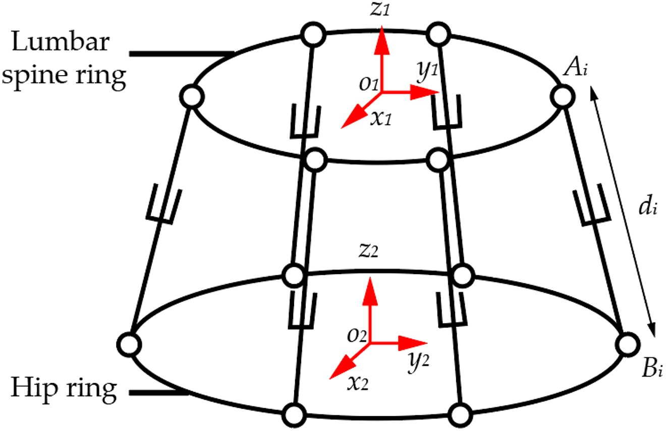
Kinematics model of 6-SPS parallel mechanism pelvis. SPS: spherical–prismatic–spherical.
Kinematics matching model
Kinematics model of 6-SPS parallel mechanism pelvis was established to study the kinematics matching at the hip joint, which is located at the movable ring. The coordinate system defining is demonstrated in Figure 4. A coordinate frame O
1 is arranged on the lumbar spine ring with the origin fixed at the center of lumbar spine ring and axes aligned to the frontal axis, the transverse axis, and the vertical axis defined in human anatomy. Similarly, coordinate frame O
2 is arranged at the thigh link. With the analysis in the second section, there are six groups of initiative prismatic joint equipped in this parallel mechanism by connecting lumbar spine ring at one end and hip ring at the other end. The connecting joints are 3-DOF spherical joint which moves passively. We denote the centers of spherical joint around the lumbar spine ring by
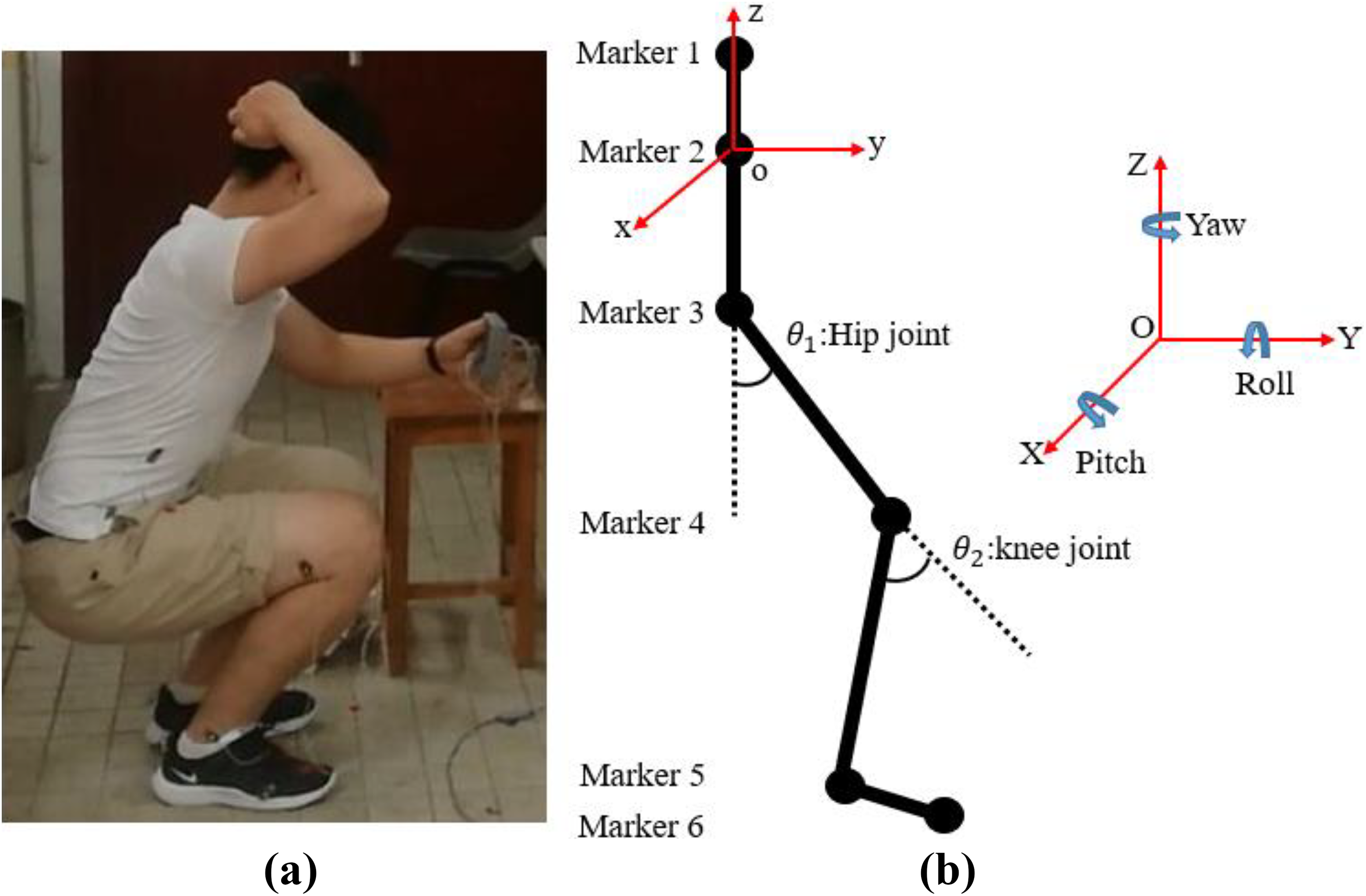
(a) Squatting gait and (b) layout diagram of markers and coordinate system.
To describe the position and orientation of hip ring, we fix the lumbar spine ring and consider it as referring coordinate system. The position and orientation of hip ring can be expressed by a transformation matrix T, which combines a translation vector P and a rotation matrix R

The translation vector P is the coordinate value of the center of movable hip ring, and the rotation matrix R is the orientation of the center refer to the fixed lumbar spine ring, which are

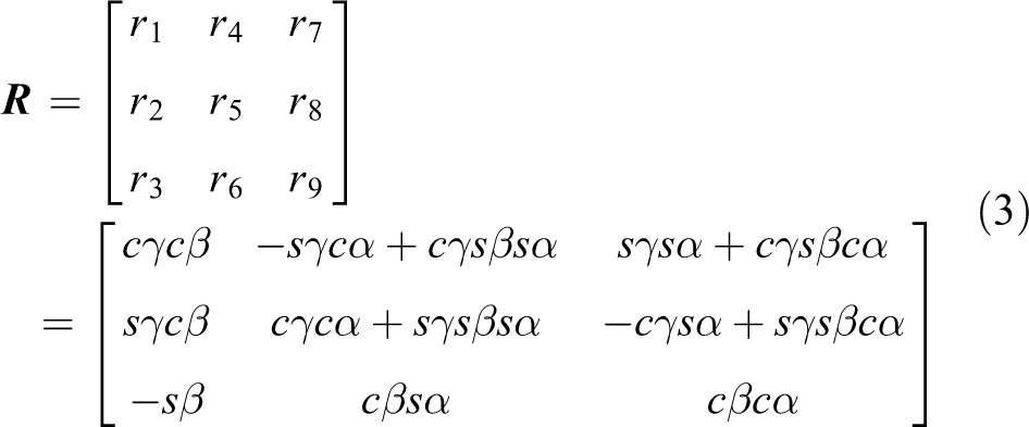
where


So,
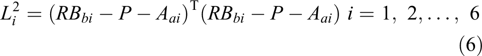
Since the rotation matrix R is orthogonal to the unit, then


The lengths of six initiative prismatic joints of the 6-SPS parallel mechanism will determine the position and orientation of the hip ring. Conversely, given any position and orientation of the hip ring, the length of six initiative prismatic joints can be calculated by equation (6).
Experiments and comparisons
Lower limb gait capture experiment
In this study, Motion capture investigator system of Optotrak Certus from Northern Digital Inc. is used as 3D optical gait capture system to collect the 3D motion data of lower limb. The Optotrak Certus System is an optical measurement device used to track the positions and motions of infrared light-emitting diodes (markers) within a specific area. In this research, six markers were attached to six positions on the volunteer’s body surface: waist, pelvic, hip, knee, ankle, and toe, respectively. Marker points at the six positions are defined as marker 1 to marker 6, respectively, as shown in Figure 4(b). The classical gaits collected were squatting down and standing up (abbreviated as squatting), as shown in Figure 4(a). The sampling time was 10 s, and a complete and stable posture data in a complete gait cycle were extracted.
The 3D coordinates of six marker points in space can be obtained by the optical motion capture system. The pitch, roll, and yaw angles of pelvic which rotate around the X-axis, Y-axis, and Z-axis can be obtained from the spatial coordinates of markers 1, 2, and 3. The result shown in Figure 5 is the pitch, roll, and yaw angles of pelvic in a complete gait cycle. By the same way, the movement at hip knee and ankle joint can be obtained.

The pitch, roll, and yaw angles of pelvic in the gait of squatting.
Simulation and assessment of series–parallel model in the hip joint
The pitch, roll, and yaw angles of the pelvis were used as the target trajectory of the 6-SPS parallel mechanism for kinematics simulation. To evaluate the synchronous motion performance of exoskeleton model and human hip joint, the 3D motion data of point B 1 on the lower movable ring were extracted and compared with the 3D data of marker 3. Therefore, marker 2 is taken as the origin of coordinates of human body, and point A 1 on upper fixed ring is taken as the origin of coordinates of 6-SPS parallel mechanism. Meanwhile, the projection of marker 3 and B 1 on the three coordinate planes is obtained by coordinate transformation, with marker 2 and point A 1 as the origin, respectively. The comparative results are shown in Figures 6 to 9.

Three-dimensional coordinate comparison of marker 3 (on human body) and point B 1 (on exoskeleton).

Error of marker 3 (on human body) and point B 1 (on exoskeleton).

Projection angle in coordinate plane.

Error of projection angle.
In Figure 6, the abscissa is the gait period, and the ordinate is the coordinate value of X, Y, and Z. X coordinate is the lateral displacement of the hip joint (marker 3) when lower limbs move, Y coordinate is the tilt displacement when moving forward, and Z coordinate is the vertical displacement.
The comparison results indicate that the absolute value of motion error in the X, Y, and Z directions are less than 3.5 mm, and the absolute value of angle error projected into coordinate plane is less than 2°. Among them, the Y direction, which is the forward direction during walking, has the smallest error and the smallest error fluctuation in the whole gait cycle. For projection angle, error of projection angle in YOZ plane, which is the rotation angle of the hip joint around X-axis, is the smallest and the smoothest. In addition, the peak errors are concentrated at 40% of the gait cycle. When the gait cycle is 40%, the test is switched from squatting to standing. At this time, no matter the coordinates or the projection angle, there is relatively large tracking error.
Discussion and conclusion
In the process of squatting down and standing up, the hip joint has lateral stride movement, forward flexion and extension, and rotation around the vertical direction. Typical LLE robots, such as those used in medical rehabilitation, can only move in a single plane and cannot actively realize lateral stride and rotation around the vertical direction. HAL is the typical commercial exoskeleton, used for lower limb assistance, which can only move in sagittal plane, so that it cannot meet the needs of lower limb assistance in outdoor auxiliary space. For a lower limb paralysis, passive freedom is difficult to play a role because the user cannot control the movement of the thigh. In this article, the anthropomorphic LLE is based on a 20-DOF series–parallel mechanism, which is active in any direction to drive the hip of the lower limbs. It can realize the walking function in all directions, so as to achieve the goal of accurately matching the movement of the wearer’s lower limbs and joints in kinematics.
When designing the series–parallel LLE, the accessible workspace of the parallel mechanism at each joint should also be considered. The isomerism of human–machine system is a common problem in existing LLE systems. There are two main consequences caused by the human–machine isomerism system: (1) the absence of exoskeleton structure movement space compared with the wearer’s movement space which will result in the structural restriction of the wearer’s limb movement, finally reducing the overall flexibility of the human–machine system and (2) the excessive space of exoskeleton structure movement space compared with the wearer’s movement space may cause the wearer’s joint injury in hyperspace.
In this article, a novel bionic LLE model is proposed based on a series–parallel hybrid mechanism. The model has twenty DOFs, with one 6-SPS parallel mechanism at the pelvis, two 3-SPS parallel mechanisms at the thigh and foot, and one 1-SPS serial mechanism at the shank. The model solves the problem that the motion of classical LLEs is restricted in sagittal plane. The model can match the movement of pelvis, hip, knee, and ankle in all directions during the movement.
What’s more, the kinematics model of 6-SPS parallel mechanism is established, and the movement data of human lower limbs are measured through experiments with the help of optical motion capture system. Finally, the synchronous effect of the model at the hip joint is assessed in this article. The synchronization effect of the model at the hip joint is evaluated by comparing the kinematics simulation results of 6-SPS parallel mechanism and the motion data collecting experiment results with the coordinates and projection angles at the hip joint.
However, this article only discusses the matching error of series–parallel LLE with the wearer’s kinematics at the hip joint when executing the squatting down and standing up motion. Although the results show that the kinematics matching effect is excellent, there is still much future work, such as the kinematics matching effect at the knee joint and the ankle joint, and the kinematics matching effect when all of these serial joints in the whole exoskeleton gather together. In addition, different gaits, such as going upstairs and downstairs, uphill and downhill, and automatic synchronization of arbitrary scenes, are also worth exploring in future research.
Footnotes
Declaration of conflicting interests
The author(s) declared no potential conflicts of interest with respect to the research, authorship, and/or publication of this article.
Funding
The author(s) disclosed receipt of the following financial support for the research, authorship, and/or publication of this article: This work was supported by National Natural Science Foundation of China (NSFC) under grant no. 51775325, the Young Eastern Scholars Program of Shanghai under grant no. QD2016033, and the Hong Kong Scholars Program of China under grant no. XJ2013015.