
Abstract
In this paper, a kinematically redundant parallel haptic device with large workspace is presented. The haptic device has a similar kinematic structure to the well-known Delta manipulator. However, it has a special arrangement of actuators and one redundant actuator added to the third leg. The proposed haptic device has essentially 4-DOF, however, only three translational DOF are used for 3-DOF positioning and force reflection, and one rotational DOF by the redundant actuator is used to increase well-conditioned workspace. If the redundant actuator's angle is controlled to follow x and y position, the haptic device has a large cylindrical workspace and can maintain good kinematic and statics performance over the whole workspace. The kinematics and workspace are analysed, and the optimal design method of finding minimum link lengths to satisfy prescribed workspace is presented. Finally, the prototype haptic device and control experiment result are presented.
1. Introduction
Haptic devices have been extensively investigated and applied to many fields, such as teleoperation, robotic surgery, bioengineering, computer-aided design, etc. In order to provide realistic force reflection and high manipulability to an operator, the mechanism of a haptic device should have low inertia, high stiffness, large force reflection capability, good kinematic conditioning, as well as large workspace, back-drivability, low friction and small moving inertia.
In general, serial-kinematic haptic devices [1–8] have large workspace, but relatively small force reflection and low stiffness. In order to further increase force reflection and stiffness, parallel-kinematic manipulators have been employed as haptic device mechanisms [9–14]. One of the most famous parallel-type haptic devices may be Delta haptics [15–18]. The Delta parallel manipulator has large force reflection and high stiffness due to parallel structure and parallelogram. However, it has a smaller workspace compared to the serial one. A new parallel manipulator similar to Delta called “Tau” with a large cylindrical workspace as with a SCARA robot is also presented [19–21]. However, the Tau manipulator consists of three different leg configurations and the kinematic performance is not symmetric. Comprehensive reviews of the mechanisms of haptic devices can be found in [22, 23]. In general, redundancy can improve the workspace and performance of a parallel manipulator [24, 25]. By adding more than one active joint to a non-redundant parallel manipulator, a kinematically redundant parallel manipulator can be constructed.
In this paper, a kinematically redundant parallel manipulator for a haptic device is conceived, which retains the advantages of both serial (large workspace) and parallel (large force and high stiffness) manipulators. The proposed parallel manipulator has the special arrangement of actuators and one redundant actuator for large workspace and good performance. The position, Jacobian and workspace analyses are performed. The optimal design to find minimum link lengths satisfying the prescribed workspace is presented. Finally, a numerical example of the optimal design, prototype haptic device and control experiment result are presented.
2. Position Analysis
As shown in Fig. 1, the kinematic structure of the proposed haptic device is similar to that of the well-known Delta manipulator with three

Kinematic structure of a Delta-like parallel haptic device.
If the redundant actuator is controlled to follow input x and y position, i.e., α = Atan2(py,px), the connecting link of the third leg (l3,2) can be kept vertically and then θ3,3 = 0. With this control method, the workspace is not limited by the range of θ3,3 and the manipulator can maintain better kinematic and statics performance over the whole workspace than that of θ3,3 ≠ 0 (refer to Fig. 3). The parallel haptic device can be treated as a 3-DOF positioning one. The first two actuators determine the x and y positions of the moving platform, and the third actuator controls the z position. If the first two actuators and the redundant actuator can make a complete circle around the z-axis, the whole workspace becomes a large hollow cylinder.

Description of the joint angles in the ith leg.
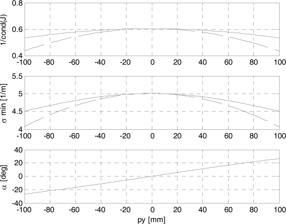
Along the y-axis (x=200, z=0 [mm])

For circular path (x=200cos(α), y=200sin(α), z=0 [mm]) (dotted line: α = 0, solid line: α = tan-1(py / px))
As shown in Fig. 1, the global reference frame is attached to the fixed base at O, and the ith local frame is attached at point Ai. It is noted that the frames A1 and A2 coincide with the reference frame.
For each leg, the following vector-loop equation should be satisfied [28].

Expressing Eq. (1) with respect to each local frame A
i
yields

where
i
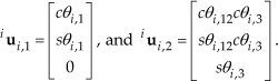
where θi,12 = θi,1 + θi,2. The position vector of

In the following analyses, it is assumed that the redundant actuator's angle α is given and the 4-DOF parallel manipulator will be considered as a 3-DOF positioning one. The inverse position analysis can be defined as the problem of finding the joint angle vector,

By summing the squares of bi,x bi,y, and bi,z in Eq. (2), an equation with only θi,2 can be obtained.

Solving Eq. (6) for θi,2 results in

where λ = (b2i,x + b2 i,y + b2i,z − l2i,1 – l2i,2) / (2li,1 li,2cθi,3). Once θi,3 and θi,2 are determined, θi,1 can be obtained from Eq. (2).

where gi,1 = li,1 + li,2 cθi,2 cθi,3 and gi,2 ≡ li,2sθi,2cθi,3. It is noted that if |bi,z| > li,2 or |κ| > 1, the given position is out of the workspace.
The problem of the forward position analysis is to find end-effector position

By summing the squares of the three components of Eq. (2′), the following sphere equation for the ith leg is obtained by

The plane equation that contains the circle of intersection made by the spheres of leg 3 and leg j is determined by subtracting Eq. (9) for i = j from Eq. (9) for i = 3:

where

Solving Eq. (10) for px and py in terms of pz and then substituting the resulting expressions into Eq. (9) for i = 3 yields
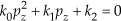
where

Once pz is found, px and py can be determined by back substitution into Eq. (10).
3. Jacobian analysis
Differentiating Eq. (2) with respect to time yields

where
i

Expressing the vectors in Eq. (13) in frame Ai gives

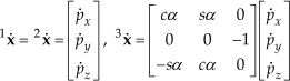
and i

where
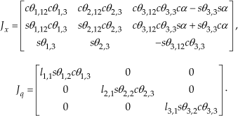
If Jq is not singular, Eq. (15) can be rewritten by

where J
Using the principle of virtual work, the statics relation is obtained by

where
The stiffness mapping in the joint space can be expressed by

where [k] = diag(k1,k2,k3) denotes a 3×3 diagonal matrix representing the joint stiffness. Applying the velocity and statics relations to Eq. (19), the stiffness mapping in the Cartesian space can be expressed by

where δx = [δpx,δpy,δpz]
T
and the stiffness matrix is given by

4. Workspace analysis and optimal design
If the redundant actuator is controlled simply with α = tan−1(py / px), the kinematically redundant parallel haptic device can have a large well-conditioned workspace. Furthermore, using the control method, the design problem can be reduced to a planar one. In other words, this manipulator is symmetric at every x′z plane with the incident angle of α to the xz plane. The optimal design will be performed on the x′z plane.
Figures 3(a) and 3(b) demonstrate that the kinematic and statics performances (isotropy condition [26] and minimum force transmission capability [27]) when using this control method are larger than those when using a fixed angle, α = 0, which is the case for a non-redundant manipulator such as the typical Delta. The isotropy condition and minimum force transmission capability are defined by

First, the minimum length of b can be selected to prevent the interference of parallelograms. The length of b is dependent on the width of a parallelogram. It is noted that a smaller length of (a – b) is desirable for smaller link lengths of leg 3 (refer to Fig. 5 and Eq. (30b)). In the prototype development, a=85 and b=35 [mm] are chosen.

Work area limited by legs 1 and 2.

Work area limited by leg 3.
Once [a, b] are determined, the objective of the optimal design can be defined as a problem to determine a set of minimum link lengths to satisfy the prescribed work area. The kinematic design variables of the optimal design are selected as

where lp1 ≡ l1,1 = l2,1, lp2 ≡ l1,2, = l2,2, lz1 ≡ l3,1 and lz2 ≡ l3,2
The prescribed work area on the x′z plane is defined as a rectangle.

The angular limits of the passive joints are chosen by

where the angular limit of the second passive joint is introduced to prevent serial singular configuration and that of the third passive joint comes from a spherical joint limit.
First, the height of the work area is limited by the second link lengths and the third joint angle limits of the first and second legs as

The next step is to determine lp1 by considering the minimum and maximum configurations of the first and second legs. For simplicity of expression, the leg number is omitted. As shown in Fig. 4, the xmin of the end-effector should be smaller than P5.


As shown in Fig. 5, the xmax of the end-effector should be larger than P1 or P3.


The minimum length of the arms (lp1) of the first and second legs can be determined by

The numerical iteration method is used to determine lp1. First, θ1,max and θ1,min are solved by using Eqs. (27b) and (28b) with assumed lp1, and xmin and xmax are calculated by Eqs. (27a) and (28a). If the condition of Eq. (29) is not satisfied, the first step is repeated with a new lp1.
Finally, lz1 and lz2 are determined by the intersection area of following inequality conditions.


In general, the work area including the prescribed one is determined by the intersection area of the four circles and –h/2 ≤ z ≤ h/2. In Fig. 6, the centres and radii related to the first and second legs are given by
Workspace plot on the x′z plane.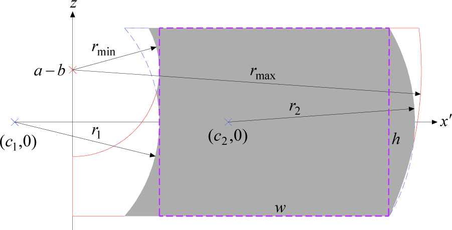

5. Prototype development and control experiment
In the prototype design, the prescribed work area and other kinematic parameters are selected as

The angular limits of the passive joints are chosen by

Since the intersection of Eqs. (30a) and (30b) does not exist for the given angular limits, βmax is modified to β'max=153° in Eq. (30a). The resulting intersection is obtained as shown in Fig. 7. In this design, the minimum lz1 (Q1) is selected for larger force transmission capability at the end-effector. Table 1 shows the optimal design result. The kinematic parameters in the prototype are slightly different from the optimal design result.
Optimized design parameters.


The intersection area of lz1 and lz2.
The workspace of the prototype haptic device is shown in Fig. 8, where the following rotary actuator ranges from the mechanical interference are considered.
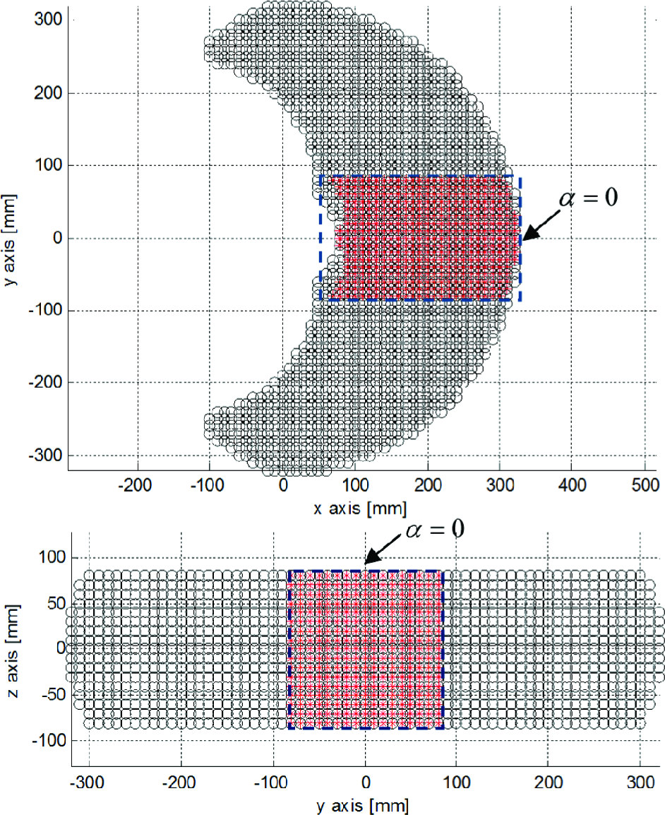
Workspace of the prototype haptic device.

It has been demonstrated that the workspace of the haptic device with a redundant actuator is much larger than that without a redundant actuator (α = 0).
Figure 9 shows the force transmission capabilities along the x-, y- and z-axes for the maximum actuator torque, τi,max =1.11 [Nm]. Figure 10 plots the diagonal element of the Cartesian stiffness matrix in Eq. (21) for the joint stiffness, ki= 55.58 [Nm/rad]. The averaged values of forces and stiffnesses are given by
Mesh plot of force transmission capability on the x′z plane. Mesh plot of Cartesian stiffness on the x′z plane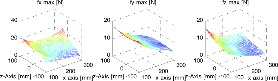
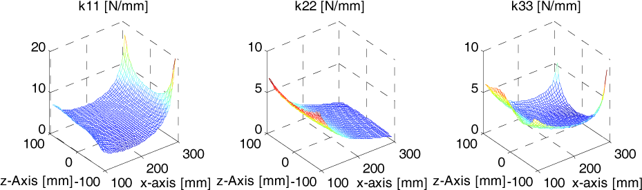

It should be noted that this device has good force reflection and stiffness along the x-axis.
As shown in Figs. 11 and 12, the 4-axis controller consists of Host PC with Simulink and Target PC with xPC Target from MathWorks. Figure 13 shows the prototype haptic device which was upgraded from the first prototype in [29]. Three DC servo motors and wire-driven gears (gear ratio=9.5:1) are used for 3-axis force reflection and joint angle sensing. The gravity force of the moving parts is compensated by the DC servo motors. One geared AC servo motor (gear ratio=45:1) is used for the position control of α.

Block diagram of a PC-based real-time controller.

System configuration of a haptic device.

Prototype parallel haptic device.
Finally, the control experiment on the redundant actuator is performed. The handle of the haptic device is moved from y = −100 to y = +100 [mm] roughly by hand as shown in Fig. 14. The actuator angles are measured by corresponding DC motor encoders, the end-effector position is calculated through the forward position analysis and the redundant actuator's angle is commanded as α = tan−1(py / px) at every 1msec. It can be seen that the redundant actuator follows the operator's position very well.
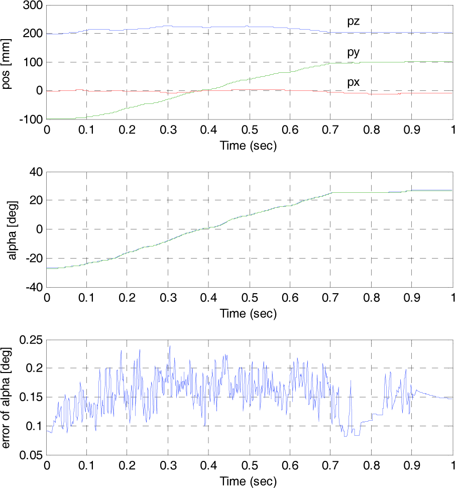
Control experiment on the redundant actuator when the moving platform moves along the y-axis.
6. Conclusion
In this paper, a Delta-type parallel manipulator with one redundant actuator is conceived for the 3-DOF positioning haptic device with a large workspace. The position, Jacobian and workspace analyses of the 3-DOF positioning parallel haptic device are presented. The optimal design method of finding minimum link lengths to satisfy the prescribed workspace is developed and applied to the prototype haptic device design. The prototype haptic device and 4-axis PC-based real-time controller using xPC target have been developed. Finally, it is demonstrated through analysis and experiment that by adding one redundant actuator to the third leg and using the simple control method of α = tan−1(py / px), the workspace can be increased significantly and good kinematic performance can be maintained over the whole workspace.
Footnotes
7. Acknowledgements
This work was supported by Kyungnam University Foundation Grant, 2009.