
Abstract
In human robot interaction systems, human intent detection plays an important role to improve the interactive performances and then the rehabilitation effects. A study is proposed to estimate the interactive forces that indirectly detect the human motion intent. A disturbance observer is designed to estimate interactive torques and friction forces without force sensors, and then a friction force model is constructed to estimate the friction force in the robot system. To detect the human–robot interaction force, we subtract the friction force from disturbance observer estimation result. Several experiments were performed to test the performances of the proposed methods. Those methods were applied in an end-effect upper limb rehabilitation robot system. The results show that the precision of the estimated sensor force can increase 5% than the force sensor. The senseless force estimation method we proposed in this article can be an alternative option in force control tasks when force sensors are not suitable.
Introduction
In recent years, the control of the contact forces as well as the trajectories between the robot and the human has become one of the key factors effecting on the post-stroke rehabilitation training. In a conventional force control system, force sensors are widely used to estimate the external force. However, the force sensor is expensive and has a limitation that reduces the robustness and performance of the system, such as the bandwidth of the force sensor is limited as a strain gauge with a soft structure is used. 1,2 Force sensors can only monitor the external force around the area where force sensor is attached. Therefore, the action could not be found outside the end effector. 3 Furthermore, the signal of the force sensor contains plenty of noise. Therefore, the problem of using force sensors is the presence of significant oscillation in the system. For that reason, it is required to design an alternative method that promotes the robustness and improves the performance of the force control system. 4 Ohishi 5 proposes a disturbance observer (DOB) scheme where disturbance torque on the motor side is compensated, and the disturbance force is obtained by estimating the parameters of the motor inertia and torque coefficient. Ohishi 6 used a direct drive mechanism including inertia viscous and coulomb friction in a force observer. 7 –9 Another approach to cope with joint friction is using joint torque sensors to eliminate the effects of friction. The joint torque sensors are installed on the robot linkage side of the gear train. And they are used as a feedback signal in a torque control loop. Joint torque sensors have been found effective in force control loops as have the use of force sensors at the end effector. 10 However, all these schemes must use additional sensors. The force estimation techniques described in this article are capable with nonideal transmission, friction and motor cogging and other effects without the need for additional force sensors.
Some motion control system has non-smooth nonlinear characteristics, such as friction, dead zone and backlash. The most familiar problem is friction force which is discontinuous with respect to velocity of the two-body surface in contact. Friction force which occurs in the system has degrading effect in the stability and performance of force control system. Moreover, heat which is caused by friction force in the system causes damage to the robot manipulator. 11
To overcome these problems caused by force sensors, several force estimation methods have been proposed in recent years. 12 –14 Since the early 1990s, force estimation observers for robotic equipment has been studied by researchers. An approach using coupled-force observer based on accurate knowledge of the robot’s dynamics was proposed. 15 Murakami constructs a decoupled DOB to estimate the external force. 16 Both the previous studies show good results while neglecting system friction. Considering the friction effect, Zahn et al. 17 proposed a force sensorless hybrid force/position control algorithm using a simplified model of robot dynamics. Friction force is estimated online by applying adaptive neural networks. Chan et al. 18 proposed a novel algorithm to simultaneous force estimation and friction compensation of a robot manipulator. Yoon et al. 19 proposed an sliding perturbation observer (SPO)-based reaction force estimation method to estimate the Coulomb friction in the surgical robot system and then observe the pure reaction force applied on it.
In the robotic manipulators, the estimator/observer is applied to observe not only friction but also the end-effector force caused by contact. 20 –22 Motor current was usually used to estimate external forces, and to deal with the noisy actuator torque measurements, a novel approach was presented. 23 In this thesis, two methods were proposed. The first method combines a recursive least squares estimation with a filtered dynamic model to estimate the external force. The second method constructs an estimator based on a generalized momentum-based DOB. The algorithm was experimentally verified in a two-degree-of-freedom (DOF) manipulator with pneumatic muscle actuators. The end-effector forces of the robot were estimated successfully. Liu et al. 24 proposed a method for the real-time estimation of contact location and contact force along a planar joint robot manipulator without using external sensory systems. Lichiardopol et al. 25 introduced a force estimator which is based on the knowledge of the dynamics of the robotic device, whereas mass of the load is typically unknown. Using this algorithm, low-frequency external forces can be estimated robustly even for quasi-statically time-varying and uncertain loads. Another method 26 suggests a bilateral controller applying SPO-based force estimation method to realize the possibility of a haptic function in a laparoscopic surgery robot system. In Jung et al., 27 a new robust estimator is proposed to estimate three-dimensional contact forces acting on a three-link robot manipulator. The estimator is based on the extended Kalman filter structure combined with a Lyapunov-based adaptation law for estimating the contact force.
For a human robot system, physical human–robot interaction (pHRI) plays an important role to improve the interactive performances and then the rehabilitation effects. 28 –30 Haptic interaction is the most important method for the pHRI. In the sensorless human robot system, we need to design an estimator to extract the end-effector force exerted by human so that the human movement intention could be effectively detected. However, the results of sensorless force estimator contain not only the interaction force but also the robot friction force which will decrease the accusation of human movement intention detection.
Based on the above discussions, a framework of sensorless interaction force estimator is proposed which is capable of dealing with human’s motion intention so that it can perform more accurately in the actual physical interaction. In this article, we propose a new friction compensation method to solve the problem of friction in robot manipulator. Disturbance observer (DOB) is applied to the end-effect upper limb rehabilitation robot (EULRR) system to estimate the friction force. After feeding back compensation friction force to the system, the friction force is reduced and the performance and robustness of the system is improved. This article is organized as follows: in the first section, the EULRR system structure is explained. The second section proposes the DOB. The third section describes the simulation setup and results. Experimental results are shown in the fifth section. The results show that the precision of the estimated sensor force can increase 5% than the force sensor. The contributions of this article are listed as follows: (i) a DOB-based force estimator is proposed; by compensating the friction force, human interaction force could be extracted accurately; (ii) the developed sensorless force estimator is proposed to deal with the uncertain nonlinear robotic dynamics, since the DOB is designed for nonlinear system; and (iii) experiments are performed on an EULRR system, for verifying the effectiveness of the proposed sensorless force estimation.
Kinetics of EULRR system
The mechanical structure of the EULRR is shown in Figure 1, which mainly consists of motor, belt, reducer, frame, rocker, sensor and a tray with a grip in space coordinates. The system has 5 DOF in total: the rocker moves along the three axes and the rotation DOF of tray turns around Z-axis and Y-axis. The movement of X/Y direction is transmitted to the reducer by the X/Y shaft motor through the belt pulley and then transmitted to the frame by the reducer. The movement of Z direction is transmitted by the Z shaft motor through the pulley to the inside of the screw. A 6-axis force/torque sensor is attached between the tray and the end of the rocker to measure the force/torque exerted by the subjects.

Mechanical structure of EULRR system. EULRR: end-effect upper limb rehabilitation robot.
Figure 2 is the simplified dynamic analysis diagram of EULRR: the left diagram shows the rocker posture in the space while the red dashed line represents the projection of rocker in the XY plane. The right diagram shows the mechanical schematic of EULRR rocker in the XY plane projection. In this diagram, OB represents the fixed rod of rocker in the XY plane projection, AB represents the movable rod of rocker in the XY plane projection. In the initial state, the movable rod (AB) is in the fixed rod (OB). When the robot begins to work, the movable rod will be pushed out of fixed rod along with Z direction by a motor

Schematic diagram of dynamic analysis.
The force analysis of the EULRR system can be calculated as presented in Table 1.
Force analysis of EULRR system.

EULRR: end-effect upper limb rehabilitation robot; τf: total friction force of the EULRR system; τs: reading of force sensor; J and J 1: moment inertia; τg: gravity torque of the whole rocker; τg1: gravity torque of the lower part that force sensor is attached.
τi is the generalized force or moment of the system, θi is the system variable, i = 1, 2,…,N. For the industrial robot, τi is the joint i used in the system to drive the generalized force or torque of the rod i, θi is the generalized coordinate of the manipulator,
Assuming that the fixed rod length of the rocker is l0, the length of the movable rod is l1, the dynamic equation of the system is obtained as

Disturbance observer
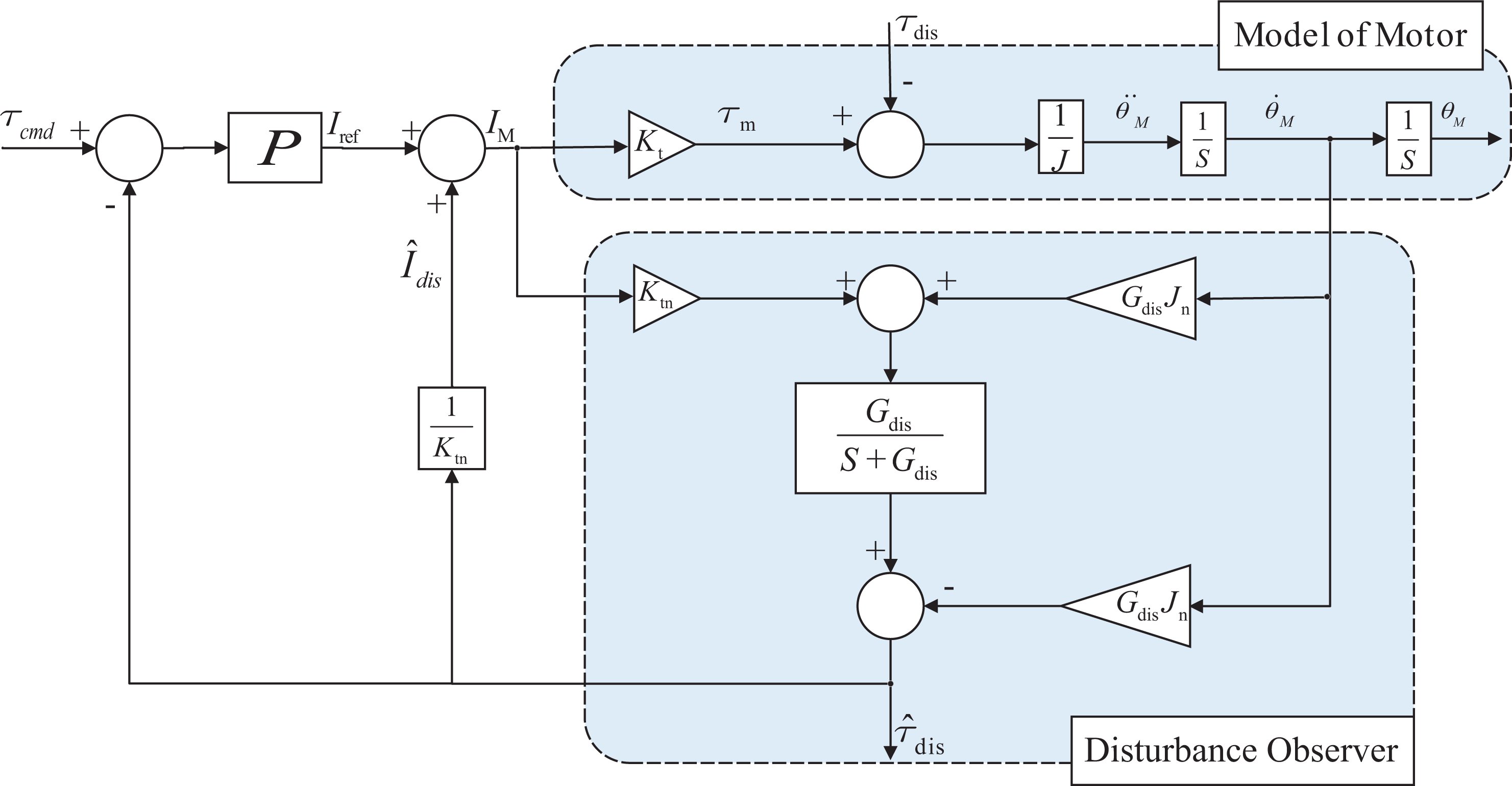
Figure 3 shows a model of an electrical motor and manipulator. Here, Ktn and Jn are the nominal torque coefficient and inertia, respectively. The system reference is the torque current reference Iref. τdis is the total disturbance torque imposed on the system, which is defined in equation


A model of actuator and manipulator.
Here, τint is the interactive torque, τg is the gravity torque, Fc is the Coulomb friction;
A DOB is a good candidate for robust control system. DOB has been used to estimate disturbance force at motor side. Then, disturbance force is compensated to the system for improving the robustness and bandwidth of control system.
The disturbance torque used the current of motor (IM) and the motor angular velocity (

where Gdis denotes the cut-off frequency of the low-pass filter. A low-pass filter is used to design bandwidth of force estimation to attenuate the high-frequency noise. By setting low bandwidth to the observer, smoothing force data with low noise are obtained. While setting high bandwidth to the observer, force data come with high noise, but the system has a fast response.
Figure 4 shows the structure of DOB with a modelling of electric motor. WhereJ denotes the moment inertia of the actuator. K
t is the torque coefficient of motor and the subscript ‘n’ represents the nominal value. I
M is the input motor current. θM,
Force control based on disturbance observer.
When the nonlinear effects generated from friction force, mechanical backlash and gravity force are compensated, the DOB techniques can observe the external force from the environment and eliminate the use of the real force sensor. This estimated method is called a reaction torque observer as shown in Figure 5. To estimate the external torque, the friction force is compensated and the high-frequency noise is filtered out using a low-pass filter.

Force control based on reaction torque observer.
Simulation setup and results
Figure 4 shows the force control based on DOB. The disturbance force that acts on any part of the robot is estimated by DOB and compensates to the system for improving the performance and robustness of the whole system, where P in Figure 4 denotes force control ratio coefficient.
The disturbance observer will estimate the external force, then compensate it in the close control loop. The real force sensor could be replaced by disturbance observer algorithm. As shown in Figure 5, this estimated method is called a reaction torque observer.
Figure 6 is the input signal compared with the output signal estimated by DOB. Figure 7 shows the torque error estimated by DOB, Figure 8 shows the input signal compared with output signal with friction force modelling and Figure 9 shows the torque error estimated by DOB with friction compensation.

Input signal compared with the output signal.

Torque error estimated by disturbance observer.

Input signal compared with the output signal with friction compensation.

Torque error estimated by disturbance observer with friction compensation.
According to the results, the friction force compensation can compensate the friction force and gives the system more stability and robustness including performance improvement.
Experimental validation
Effectiveness of the proposed force control algorithm is verified by experiments. The EULRR system depicted in Figure 1 is used as the experimental apparatus.
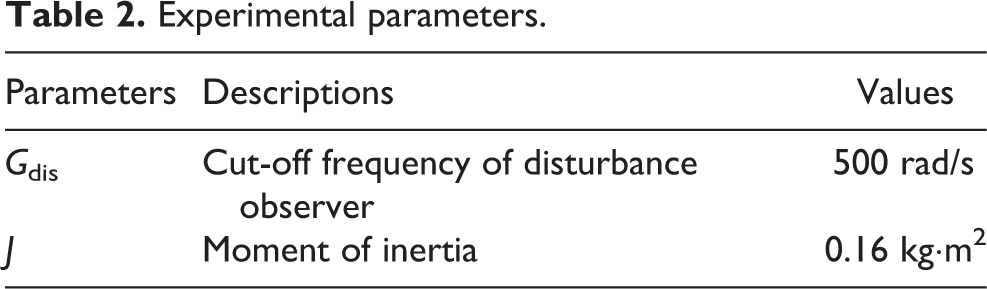
The parameters used in the experiment are listed in Table 2.
Experimental parameters.
According to the force analysis formula, we can estimate the reading of the force sensor τs. To estimate the sensor readings τs, the friction force should be identified and compensated. We can use the force analysis formula and Figure 4 to identify the total friction force of the EULRR system. The estimation of the friction force can be found as shown in Figure 10.

Friction force model.
From the identification result, the friction force model can be combined with the linear least squares method and the sigmoidal function. Based on Figure 10, the calculation of the linear least squares methods is given in equations (4) and (5); on the other hand, the sigmoidal function is given in equation (6)


We can use the identified system friction model to compensate the friction force of the EULRR system. We will put a force signal which varies from −30 N to 30 N on the EULRR system. Experiments are designed according to the force analysis formula in Table 1 and force control algorithm based on reaction torque observer.
Figure 11 shows the experimental results with environment by the force sensor and the reaction torque observer. The result shows that the precision of the estimated sensor force can increase 5% than the force sensor. There is some noise on the estimated force signal. This noise normally occurs due to the specifications of the motor and encoder.

Force sensor compared with estimated sensor force.
Experimental design of interactive force estimation
As shown in the experimental platform in Figure 12, the X-axis and the Y-axis of the terminal hauling upper limb rehabilitation robot are independent of each other, so we apply the constant force to the X- and Y-axes separately. At the end of the rocker is a rope, one end of the rope is tied to the end of the rocker, and the other end is tied to the weight. Because the rope only changes the direction of the force transfer and does not change the size of the force transfer, we apply a constant force to the end of the rocker in the motion process which can change the force by changing the weight of the weight.

Experimental platform for estimating external force.
According to the previous section, we build the Simulink control model, as shown in Figure 15, in which the torque observation window is the moment of the friction force of the system.
Experimental platform for interactive force estimation
Simulink real-time workshop (RTW) combines the functions of XPC Target and XPC Target Embedded Option, allowing people to create real-time applications from the Simulink model and run them on the dedicated target computer hardware connected to the physical system. It supports real-time simulation and testing, including rapid control prototyping, DSP and visual system prototyping and hardware-in-the-loop (HIL) simulation.
RTW can use the driver block to extend the Simulink model, automatically generate real-time applications and perform interactive data or automatic running programs on a dedicated target computer equipped with a real-time kernel, multi-core CPU, universal I/O and protocol interfaces. Simulink and the hardware design of the target computer work together to create a real-time system for interactive interface and on-site environment. RTW can also be used with custom target computers and I/O hardware.
The test of the friction force is carried out on the HIL platform. The HIL platform works with the help of the rapid control prototype (RCP) technology, MATLAB simulation tools, the real-time online simulation of the control system, the online modification of parameters, online recording data and other functions. The system framework is shown in Figure 13, and the HIL platform is shown in Figure 14.

System communication framework.

Hardware in the loop platform.
The virtual controller formed by the graphical programming of Simulink is run on the development machine. The motor driver is used as the actual control object. The virtual controller + the real object simulation system is called the fast control prototype. It is a kind of semi-physical simulation of the system. The RCP simulation is in the second stage of the development of the control system. Before the development of the product, the designer’s new control ideas (Methods) can be easily and quickly tested on real-time hardware. Through real-time testing, the existing problems can be found at the early stage of the design to modify the prototype or parameters, and then carry out real-time testing, so that a reasonable and feasible control prototype for the user needs is created. The C code actually runs on the target machine.
Using the advantages of hardware in the ring platform, save the controller, control the motor drive directly by the target machine, shorten the product development cycle, improve the development efficiency, save the cost and reduce the R&D cost.
Design of interactive force observer based on DOB
Figure 15 is a DOB for estimating frictional force, and the formula for estimating the disturbance force is


DOB for estimating friction. DOB: disturbance observer.
When the rocker moves at uniform speed, the angular acceleration

When the rocker is deflected in different angles, the gravity term τg can be calculated by the kinematics of the upper limb rehabilitation robot system, and the torque value of the motor
The estimated values of friction are approximated, so that the formula of the system gravity compensation and friction force is added to the system control program, and the system control block diagram is shown in Figure 16.

Block diagram of interactive force observation after compensation.
The interaction force estimated by the observation window at this time is

Since the friction model of the system is known, the interaction force τ int can be calculated according to formula (9), so that the motion intention can be solved.
Experimental results of interaction force estimation
The interaction force estimation experiment on the interactive force estimation experimental platform is divided into the single-axis interactive force estimation experiments in two directions of the X-axis and the Y-axis. In the experiment, the weights drive the rocker to carry on the active motion, and the value of the interaction force detected by the sensor during the recording process is shown in Figure 17.

DOB force response curve of X-axis with friction compensation. DOB: disturbance observer.
The purple square wave line in Figure 17 indicates that the size of the actual interaction force is changed with time by the X-axis weight. The blue curve is the change curve of the interaction force estimated by the X-axis, the yellow curve indicates the reading of the sensor in the direction of the X-axis, and the brown line is the change of the rocker position with time in the experiment of the interaction force estimation.
The following conclusions can be drawn from the response curve: It can be seen from the diagram that the estimated interaction force follows the actual value of the actual weight reference moment and is consistent with the trend of the force sensor readings, and the trend and magnitude of the estimated results of the interaction force observer are in advance. In the steady state of the 5–10 s, the numerical fluctuation of the reference force exerted by the weights is smaller. Because the system friction and gravity are compensated by the interaction force observer, the estimated force is closer to the actual force than the sensor measurement. The reason for the delay might be the DOB uses position and speed information instead of using the acceleration information. The changes in acceleration are the direct result of external force disturbance, while the position and speed are indirect result of disturbance. The design of Q(s) bandwidth should be the trade-off between the robust stability and the interference suppression capability of the DOB. Between the 10–15 s and the 30–35 s, the force of the estimated force and the force measured by the sensor decreased. This is because the force of the weights applied to the end of the rocker through the rope has changed with the deflection angle of the rocker, and the force exerted at the end of the rocker is obviously decreased when the angle of the rocker is larger.
The same force estimation experiment was carried out on the Y-axis. The experimental results are shown in Figure 18.

DOB force response curve of Y-axis with friction compensation. DOB: disturbance observer.
Conclusion
This article presents the friction compensation method to compensate the friction force which is applied in the robot system. From the simulation results, the system which contains friction force compensation shows better performance and robustness. We present successful results from implementation of a DOB algorithm on the EULRR system, for torque estimation purposes. This force observer has been integrated in a common force control scheme in the EULRR system. The results show that the precision of the estimated sensor force can increase 5% than the force sensor. Experimental results have shown how this force observer can be alternatively used in force control tasks when force sensors are not suitable. For the future work, the proposed method can be applied in many industrial robots to eliminate the friction force that appears in the system.
Footnotes
Declaration of conflicting interests
The author(s) declared no potential conflicts of interest with respect to the research, authorship and/or publication of this article.
Funding
The author(s) disclosed receipt of the following financial support for the research, authorship, and/or publication of this article: Major scientific and technological projects for social development in Ningbo City, No. 2016C11021.