
Abstract
Motor rehabilitation strategies for treating motor deficits after stroke are based on the understanding of the neural plasticity. In recent years, various upper limb rehabilitation robots have been proposed for the stroke survivors to provide relearning of motor skills by stimulating the motor nerve. However, several aspects including costing, human–robot interaction, and effective stimulation of motor nerve still remain as major issues. In this article, a new upper limb rehabilitation training system named as motion intention-based virtual reality training system is developed to close the aforementioned issues. The system identifies the user’s motion intention via force sensors mounted on the rehabilitation robot to conduct therapeutic exercises and stimulates the user’s motor nerve by introducing the illusion of immersion in virtual reality environment. The illusion of immersion is developed by creating Virtual Exoskeleton Robot model which is driven by user’s motion intention and reflecting the motion states in real time. The users can be present to the training exercises by themselves and fully engage in the virtual reality environment, so that they can relax, move, and recreate motor neuro-pathways. As preliminary phase, six healthy subjects were invited to participate in experiments. The experimental results showed that the motion intention-based virtual reality training system is effective for the upper limb rehabilitation exoskeleton and the evaluations of the developed system showed a significant reduction of the performance error in the training task.
Keywords
Introduction
Stroke is a major cause of acquired physical disability in adults worldwide. Motor deficits affecting the upper limb are a common manifestation of stroke and greatly contribute to decreasing the individual’s functional performance. 1 It is widely appreciated that motor rehabilitation after stroke plays an essential role in reducing the individual’s physical disability. 2 The rehabilitation strategies for treating motor deficits after stroke are based on the understanding of the neural plasticity which is known by the phenomenon that the human brain changes itself in response to different types of experience through the reorganization of its neuronal connections. 3 To exhibit the neural plasticity, motor relearning is the most important matter because it can produce changes in synapses, neurons, and neuronal networks within specific brain regions. 4 Exoskeletons are robotic systems designed to work linked with parts (or the whole) of the human body. The robotic exoskeleton structure is always maintaining contact with the human operator’s limb. It can be suitably employed in robotic-assisted rehabilitation to assist the users to proceed relearning movement training exercises. And it can also make the process of upper limb rehabilitation repeatable, with objective estimation and decrease the dependence on specialized personnel availability.
About 30 existing robotic exoskeleton devices are reviewed by Proietti et al. 5 As it has been mentioned, most publications in the field of exoskeletons focused only on mechatronic design of the devices, while we do believe a paramount aspect for robots potentiality lays on the control side. So the development of innovative and improved human–robot interaction control strategies will make a certain contribution to the upper limb rehabilitation assisted by the robotic exoskeleton devices.
The virtual reality (VR) technology has been proved useful in terms of motivating and challenging patients for longer training duration and cadence, modifying patient’s participating level, and updating subjects with their training performance. 6 VR-based rehabilitation protocols may significantly improve the quality of rehabilitation by offering strong functional motivations to the patient who can therefore be more attentive to the movement to be performed. VR can provide an even more stimulating video game-like rehabilitation environment when integrated with force feedback devices, thus enhancing the quality of the rehabilitation. 7
An upper limb force feedback exoskeleton for robotic assisted rehabilitation in VR is presented in Frisoli et al. 8 A specific VR application focused on the reaching task was developed and evaluated in the system, but the system can’t provide adjustment when the reaching is far away too much. And little details are given to the control aspects of the robotic exoskeleton. An assistive control system with a special kinematic structure of an upper limb rehabilitation robot embedded with force/torque sensors is presented by Chen et al. 9 A three-dimensional (3-D) GUI system for upper limb rehabilitation using electromyography and inertia measurement unit sensor feedback is developed by Alhajjar et al. 10 It encourages the patients by recording the results and providing 3-D VR arm to simulate the arm movement during the exercise. A haptic device and an inertial sensor are used to implement rehabilitation tasks proposed by Song et al., 11 the system provides the vision through the monitor and force feedback through the haptic device. Gesture therapy was presented by Sucar et al., 12 a VR-based platform for rehabilitation of the upper limb was introduced. Similarly, the patients’ use of a home-based VR system portrayed by Standen et al. 13 provides a low-cost VR system that translates movements of the hand, fingers, and thumb into game play which was designed to provide a flexible and motivating approach to increasing adherence to home-based rehabilitation. It is suitable for the patients with slight independence ability, which doesn’t have to be assisted by the robotic exoskeleton.
By considering all the aforementioned limitations, motion intention-based virtual reality training system (MIVRTS) is developed by integrating motion intention identification-based upper limb therapeutic exercises and the illusion of immersion in VR. The system identifies the user’s motion intention via force sensors mounted on the rehabilitation robot to conduct therapeutic exercises and stimulates the user’s motor nerve by introducing the illusion of immersion in VR environment. The illusion of immersion is developed by creating Virtual Exoskeleton Robot model which is driven by user’s motion intention and reflecting the motion states in real time.
The rest of the article is organized as follows. “The rehabilitation robotic exoskeleton” section presents the main features of the rehabilitation robotic exoskeleton system. An overview of the developed MIVRTS system employed in this study for the validation of the exoskeleton in upper limb rehabilitation is given in “MIVRTS system” section. In “Motion intention-based application” section, the motion intention identifying method is described and an application for rehabilitation exercises is developed. “Evaluation on six participants” section explains the experiment and evaluation results, followed by conclusion described in the final section.
The rehabilitation robotic exoskeleton
In this study, the rehabilitation strategy is implemented on a five-degrees of freedom (DOF) exoskeleton with a wearable structure and anthropomorphic workspace that can cover the full range of motion of a human arm 14 which is portrayed in Figure 1. Its mechanical structure is consisted of five-piece irregular connecting rod in series. 15 The rotation angle of each joint has a certain limit considering the rehabilitation safety factor. All the five DOFs are both actuated by motors and monitored by encoder sensors, while the first two motors are AC servo motors which are communicated to the central controller through a control card, the last three motors are DC servo motors which are communicated to the central controller through serial ports. All the motors of the exoskeleton are located at the rotation center of each joint. It is a general robotic exoskeleton for the rehabilitation of upper limb.

5-DOF upper limb rehabilitative exoskeleton robot. DOF: degrees of freedom.
MIVRTS system
Motion intention detected setup
The diameters of the upper arm ring and the lower arm ring are all bigger than that of human beings in order not to cause any major difficulty for the poststroke patient to wear it. However, it is harder to make the affected limb fixed and to detect the interaction information. In the active training exercises, the identification of motion intention is the crucial factor to conduct the rehabilitation strategies. Dynamics modeling 16,17 is to let the measured joint torques compare to the calculated joint torques from the exoskeleton dynamic model, and the difference is the motion intention. But the joint torque sensors are too expensive and it requires very high modeling and installation accuracy. The human–robot interface based on force sensing register (FSR) 18 has a very high cost performance. But it is designed for the open joint exoskeleton, and a state model is needed to estimate the intentional reaching direction.
Considering the aforementioned limitations, a motion intention detector (MID) system is developed as having been portrayed in Figure 2. The MID consists a group of FSRs and inflatable rings. The FSR sensors used in MID are to measure the human–robot interaction forces. These forces can be transformed in to the interaction torques as a result of the sensors are mounted on the fixed places of the exoskeleton. And an impedance-based interaction controller which will be discussed in detail in the next section can conduct the active training exercises relying on the interaction torques. The inflatable rings are mounted on the upper arm ring (where has been indicated in Figure 2) and lower arm ring (which doesn’t depict in the figure for brevity). They will be aerated after the subject wears on to make the affected limb fixed on the exoskeleton and easily to measure the interaction forces.

Structure of MID system. MID: motion intention detector.
Integration with VR environment
The block diagram in Figure 3 represents the main components of the rehabilitation setup. The VR environment exchanges information with the interaction controller of the exoskeleton, receives motion state feedback from the exoskeleton and shows out, and provides visual/acoustic feedback to the patients who are interacting with the exoskeleton. The doctor designs training tasks which will be instructed to the patient previously, sets interaction parameters during the rehabilitation training process, and receives quantitative results of training performance. The patient will see an avatar of the exoskeleton representing his movements in the virtual environment and is able to recognize whether or not the performance is correct through the feedback from the VR environment.

Block diagram of MIVRTS. MIVRTS: motion intention-based virtual reality training system.
The VR environment is implemented by C++ API of OpenSceneGraph, 19 which is an open source high performance 3-D graphics tool kit, used by application developers. It provides a scenario which is focused on the tracking movement as shown in Figure 4.

A scenario of VR environment. VR: virtual reality.
A prescript trajectory and an avatar of the exoskeleton are presented in the virtual environment at first. Then, a blue ball is set on the trajectory where the nearest point to the end point of the exoskeleton is present. The interaction controller will drive the end point of the exoskeleton close to the blue ball. If they are near enough, it means that the exoskeleton is tracking, the blue ball will be twinkling. When motion intention is detected, the interaction controller will drive the exoskeleton to a new motion state, the blue ball will follow the motion state on the prescript trajectory and keep twinkling if it is tracking. In Figure 4, the blue trajectory is the prescript trajectory and the red trajectory is the real motion loci of the end point of the exoskeleton. The screen shot of action page in MIVRTS GUI is illustrated in Figure 5.

Screen shot of action page in MIVRTS GUI. MIVRTS: motion intention-based virtual reality training system.
Motion intention-based application
Motion intention-based interaction control
Once the interaction torque signals of each joint are measured in “Motion intention detected setup” section, the rehabilitation exoskeleton robot needs to make a change according to the current motion state and the measured torques, in response to the change of each joint torque in the interaction, and to realize compliant interaction between human upper limb and rehabilitation robot. An interaction control method derived from impedance control is adopted to leave the subject the possibility to actively conduct the training task and being guided by the exoskeleton robot only when the end point of the exoskeleton is too far away from the blue ball on the prescript trajectory. The impedance interaction is defined as the relationship between the interaction torque τ h of each joint and the motion state of end point

where J is the Jacobian matrix of the exoskeleton robot
20
and JT is the transposed form. Fg is the extra gravity compensated force, it is equivalent to that there is a virtual hand holding of pulling the end point of the exoskeleton. It can be transformed into the compensated torques of each joint by the Jacobian matrix and interact with the measured interaction torques. X and X0 represent the position of the end point from the exoskeleton and the nearest position to the end point on the prescript trajectory, respectively. The velocity of the end point

It can be obtained from the formula (2) that the target velocity of each joint will change according to the variation of the interaction torques from the corresponding joint during the active training exercises. The degree of the current speed changes depend on the interaction torques, the deviation from the reference trajectory of the end point, and the damping impedance coefficient K2. When the position of the end point deviates from the prescript trajectory, which means that X0 ≠ X, the target velocity of each joint will adjust accordingly to guide the subject to move back to the reference trajectory
The range of the adjustment depends on the stiffness and the damping impedance coefficient K1 and K2.
The target velocity of each joint q which is output from the interaction controller will serve as the target value of the model free adaptive sliding mode controller (MFASMC), 22 to conduct the speed tracking of the exoskeleton robot and achieve the control of the actively interaction training exercises. The structure of the interaction control system is shown in Figure 6. As shown in Figure 6, a simulation of the exoskeleton system has been developed to evaluate the idealized behavior of the interaction control system using Simulink of Mathworks. The simulation consists of a five DOF exoskeleton robot model which is imported from the SolidWorks project by SimMechanics, the interaction control strategy, the speed controller of MFASMC, a trajectory generator, and the interaction torques. Figure 6 has portrayed the simulation model in detail, where signal 1is the end point trajectory of the exoskeleton robot; signal 2is the joint angles feedback from the exoskeleton robot; and signal 3 is the interaction torques, which can be seen as the disturbance of the exoskeleton model.

Simulation model structure of the interaction control system.
Experiment and Simulation
Since the communication mode of the five motors of the exoskeleton is inconsistent what is mentioned anterior. The first two motors are used to implement the verification experiment. The impedance parameters of the interaction controller are set as K1 = 300N/m and
Interaction results of simulation and experiment.

Interaction torques of simulation and experiment.
Based on the above simulation, two simulations considering the gravity compensated force are conducted. The gravity compensated forces are set as

Five-DOF upper limb rehabilitative exoskeleton robot. DOF: degrees of freedom.
Evaluation on six participants
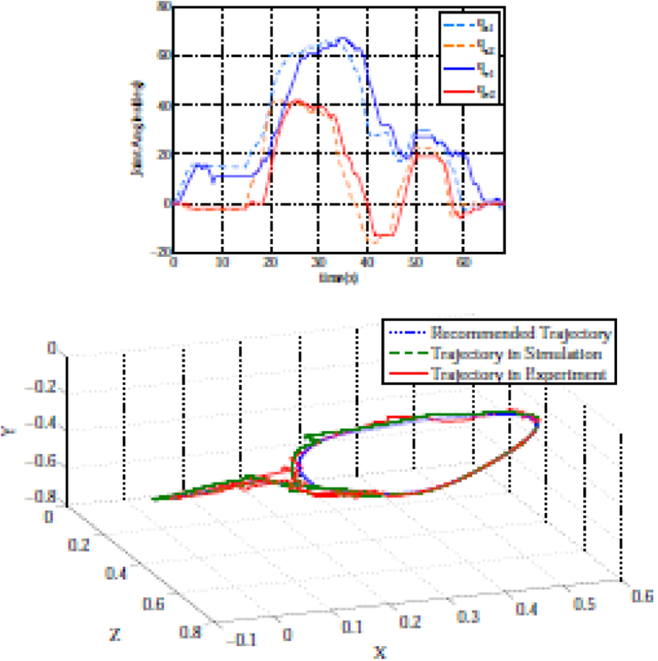
As preliminary experiment, six students with normal eyesight and sense of touch were invited as participants in the experiment. The experiments were conducted in a quiet environment as the concentration of the participant is important in the MIVRTS experiment. Before the experiment, all of the participants were explained how the system worked and given time to practice. At first, they worn the exoskeleton that was mounted with the MID. Then, the participants moved their upper limb along the recommended trajectory and the experiment started. The action page of the MIVRTS GUI is visible all the time. The parameters of the interaction controller are the same with the above experiment with zero gravity compensated force. The training exercises was conducted for five times with 3 min interval for each participant. The experiment results before and after the training exercises are recorded in order to compare the performance. And the experiment results of the six participants are portrayed in Figures 10 to 15. The evaluation results of the six participants are listed in Table 1. Where s and V represent the root mean square values and the variance values of the deviation separately.

The experiment results of the first participant.

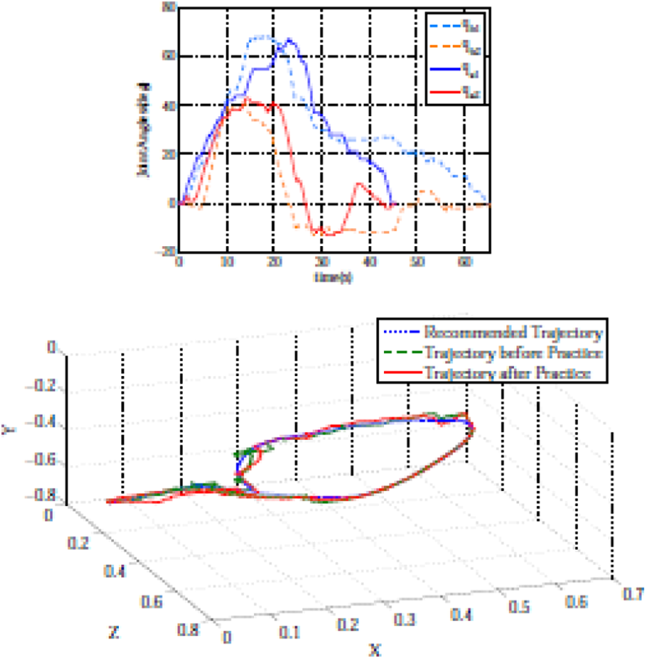
The experiment results of the second participant.

The experiment results of the third participant.

The experiment results of the fourth participant.

The experiment results of the fifth participant.
The experiment results of the sixth participant.
The evaluation results of the six participants.

It is obvious that the first two participants did not complete the experiment before the training exercises as the end point did not back to zero. All the participants complete the experiment after five times training exercises and the required time shortened in different degrees. The root mean square values of the deviation after training exercises sa are smaller and more steady than that sb before training exercises.
Conclusion
This article has presented a MIVRTS for the upper limb rehabilitation exoskeleton robot to provide motor rehabilitation strategies by stimulating motor nerve. The system identifies the user’s motion intention by a MID which is implemented via force sensor registers. A motion intention-based interaction control method was derived from the impedance control algorithm. It makes the training exercise process be conducted by the motion intention of the patient and constricted by the prescript trajectory. The interaction control method has a high cost performance and is valid in experiment and simulation. A graphical user interface about the illusion of immersion in VR environment was developed to feedback the motion state of the user’s upper limb in real time. The users can be present to the training exercises by themselves and fully engage in the virtual environment, so that they can relax, move, and recreate the motor neuro-pathways. All the simulations and experiments arrive at a conclusion that the MIVRTS system is effective for the upper limb rehabilitation exoskeleton.
Footnotes
Declaration of conflicting interests
The author(s) declared no potential conflicts of interest with respect to the research, authorship, and/or publication of this article.
Funding
The author(s) disclosed receipt of the following financial support for the research, authorship, and/or publication of this article: This work is supported by “Fundamental Research Funds for the Central Universities” (N150804001), 2015 Liaoning province Doctoral Fund (201501142), and National Natural Science Foundation of China (61503070).