
Abstract
Existing commodity RGB-D sensors have a limited field of view compared with a nearly 360° horizontal field of view of Lidar. This article presents a method to extend the field of view by stitching depth and color images from multiple RGB-D sensors to form a depth and a color panorama. Firstly, a set of 3-D matched key points are constructed based on 2-D matched key points and corresponding depth values to estimate transformation matrices between multiple RGB-D sensors. Then, depth and color images are projected to the 3-D space using estimated transformation matrices to construct textured 3-D points. Finally, projecting textured 3-D points to a compositing surface can create the depth panorama and the color panorama. Experiments validated the accuracy and efficiency of the proposed method.
Keywords
Introduction
LIDAR is a 3-D scanning device with a 360° field of view (FOV) that measures the distance to a target by illuminating the target with pulsed laser light and measuring the reflected pulses with a sensor. LIDAR is widely used in autonomous driving for its high accuracy and considerable measuring distance to detect obstacles, plan motion, construct high-definition maps, and so on. 1 –3 However, people tend to use structured light-based RGB-D sensors (Microsoft Kinect v1, Intel RealSense, etc.) to measure distances of objects in relatively small-scale applications of moving robots such as indoor mapping and localization, human–robot interaction, and path planning for their relatively low price and more dense depth images. 4 –6
Structured light-based RGB-D sensors measure distances of objects using efficient light-coding technologies. The depth sensor of the RGB-D sensor consists of an infrared (IR) projector combined with an IR camera. The IR projector projects a set of IR dots in 3-D space and the IR camera observes each dot and matches it with a dot in the known projector pattern to obtain a depth image. These RGB-D sensors are low cost and can provide a depth image with a video graphics array (VGA) resolution (640 × 480) at video rate (e.g. 30 Hz) using only the on-board calculation unit. One main drawback of RGB-D sensors is the limited FOV. The Kinect v1, for example, has a horizontal FOV of 57°. Thus, only the frontal side of objects can be observed.
In this article, we propose a novel method to stitch depth and color images from multiple RGB-D sensors to form depth and color panorama to extend the FOV of a single RGB-D sensor. Firstly, we construct a set of matched 3-D key points to estimate transformation matrices between multiple RGB-D sensors by minimizing the alignment error of matched 3-D key points using a nonlinear least squares method. These matched 3-D key points are constructed by integrating the 2-D key points extracted from color images and corresponding depth values from depth images. Then, color images together with depth images are projected to the 3-D space based on estimated transformation matrices. Finally, both depth and color panorama with extended FOV are obtained by projecting the depth and color images in 3-D space to a compositing surface.
Related works
There are many works about using multiple RGB-D sensors to extend the FOV. According to the arrangement of multiple RGB-D sensors, related works can be grouped into two categories: multiple RGB-D sensors that face inward 7,8 and face outward. 9 –11 When multiple RGB-D sensors are placed to face inward, they are used to cover all sides of an object for 3-D reconstruction. We focus on multiple RGB-D sensors that face outward for sensing the surrounding environment.
The primary step in stitching images (color or depth) into a panorama is to estimate transformation matrices between different cameras. In the traditional method of stitching color images, 10,12 since they have do not have access to the depth coordinates of pixels in a color image, transformation matrices are estimated based on matched 2-D key points in different images. The main disadvantage of these methods is that estimated transformation matrices are depth-dependent which means if distances between objects and the camera change, transformation matrices have to be reestimated.
In comparison, the RGB-D sensor provides a color image along with a depth image. Using only depth images or integrating with color images, depth-independent transformation matrices can be estimated. Song et al. only used depth images to calculate perspective transformations from other RGB-D sensors to a common plane. 9 The generated depth panorama is distorted due to the perspective transformation. Fernandez-Moral et al. proposed to calibrate multiple RGB-D sensors using lines 13 or planes 14 that have large spatial spans to be observed by multiple RGB-D sensors. In the study by Fernandez-Moral et al., 14 only depth images of planes are used, and in the study by Perez-Yus et al., 13 color images are used to extract lines and depth images provide coordinates of lines in 3-D space.
In contrast to previous works on stitching depth-dependent panorama using only color images or depth-independent panorama using plane or line features in both depth and color images, we proposed an accurate and efficient calibration method which estimates extrinsic parameters through constructing matched 3-D key points using point features in both depth and color images. Furthermore, a distributed capturing system is also presented to capture depth and color images from multiple RGB-D sensors in real time.
In the following, we give the details of our calibration approach and the construction of depth and color panorama using estimated calibration parameters. Then, experiments are taken to evaluate the accuracy and efficiency of the proposed stitching method using a multi-RGB-D camera rig. Finally, conclusion and future work are outlined.
Method
Method overview
Figure 1 shows the flowchart of the proposed method for constructing the depth and color panorama using depth and color images from multiple RGB-D sensors. The input to the method is depth and color images captured from multiple RGB-D sensors. We extract 2-D key points from color images and integrate with corresponding depth values from depth images to construct a set of matched 3-D key points to estimate transformation matrices between multiple RGB-D sensors. Then, multiple depth and color images are projected to 3-D space using estimated transformation matrices to construct textured 3-D points. Finally, the depth and color panorama are obtained by projecting textured 3-D points to a compositing surface.

Flowchart of the proposed method for constructing the depth and color panorama.
Construct matched 3-D point sets
There are a color camera and a depth camera in a single RGB-D sensor. In this process, we first extract SURF key points from pairs of color images captured by color cameras in neighboring RGB-D sensors. Then, integrating with depth values in-depth images are captured by corresponding depth cameras to construct matched 3-D points.
Due to different positions of the depth and color camera in an RGB-D sensor, the depth image is not aligned with the color image. Although the software development kit (SDK) of RGB-D sensors can do the alignment process automatically using the factory parameters, users may want to obtain these parameters by themselves for higher precision. Thus, the details of aligning the depth image with the color image are briefly presented here.
To align the depth image with the color image, intrinsic parameters of each camera and transformation matrices between the depth and color camera are needed to be known. These parameters can be obtained by the SDK of RGB-D sensors. For higher precision, the standard chessboard-based calibration method 15 can be used to get these intrinsic parameters. Since all RGB-D sensors we used are new, and intrinsic parameters obtained from SDK and the chessboard-based calibration method are almost the same, we used intrinsic parameters that are obtained from SDK in this article for efficiency.
Let K
c and K
d represent the intrinsic parameters of the color camera and the depth camera, respectively, T
cd represent the transformation matrix between them. Let

After aligning the depth image with the color image, the SURF key point detector is used to determine well-matched key points in pairs of images. Let
Furthermore, to improve the accuracy and efficiency of detecting matched key points. The SURF key point detector is only applied to the overlapping regions of an image pair, and a random sample consensus (RANSAC)-based filtering method is applied to refine matches. The overlapping regions can be roughly estimated by the FOV of an RGB-D sensor and the include angle between pairs of RGB-D sensors. In the RANSAC-based filtering method, RANSAC is used to select the best subset of corresponding key point pairs through estimating the homography matrix. A re-projection error threshold is predetermined to help the RANSAC-based filtering method to distinguish inliers from outliers.
Figure 2(a) and (b) shows the matched key points when the SURF key point detector is applied to the whole image and overlapping regions (blue rectangles), respectively. Well-matched key points are connected with green lines, and poorly matched key points are connected with red lines. There are 65 well-matched key points and 11 poorly matched key points in Figure 2(a) and 62 well-matched key points and 7 poorly matched key points in Figure 2(b). After applying the RANSAC-based filtering method, only well-matched key points (24 pairs) are left as shown in Figure 2(c).

(a) The detected matched key points when the key point detector is applied to the whole image. (b) The detected matched key points when the key point detector is only applied to the image regions within blue rectangles. (c) The matched key points when the random sample consensus (RANSAC)-based method is applied to refine the matched key points in (b). Well-matched key points are connected with green lines, and poorly matched key points are connected with red lines.
Estimate transformation matrices from matched 3-D point sets
The estimation of transformation matrices from 3-D point sets is a class of iterative closest point (ICP) problem. The ICP-based method estimates the transformation between two point clouds by minimizing the point-to-point distance metric. For each point in the source point cloud, the closest point in the reference point cloud is selected to estimate the point-to-point distance. Thus, ICP-based method cannot handle a large displacement.
In our method, matched 3-D points are already selected through matched key points in color images. The displacement between 3-D point sets (i.e. the relative displacement between two RGB-D sensors) can be larger, so long as matched key points can be extracted. There exists an analytic solution for the transformation between two point clouds when 3-D point correspondences are known. 16 Because of the measurement error of the RGB-D sensor (about 1 mm at 1 m distance 17 ), we chose to construct a nonlinear least squares formulation based on the square point-to-point distance of matched 3-D points and used the Levenberg–Marquardt (LM) algorithm to iteratively solve the formulation.
Let

We use the standard LM algorithm to solve equation (2). The derivative of equation (2) with respect to ξ is given by

where
Figure 3(a) and (b) shows panoramic point clouds that are constructed from depth and color images captured from two RGB-D sensors using poses that are estimated using generalized iterative closest point (GICP), 18 a state-of-the-art implementation of the ICP algorithm and the proposed approach, respectively. The two RGB-D sensors share an FOV with 50% overlap. Corresponding color images are presented in Figure 2. As shown in Figure 3(a), two point clouds are not correctly aligned, because it can not handle large displacement. The alignment result using the proposed calibration method is shown in Figure 3(b), two point clouds are well aligned. Note that there is a small misalignment of the table in Figure 3(b), this is because the table is too close to the RGB-D sensor and depth values of the table are invalid.
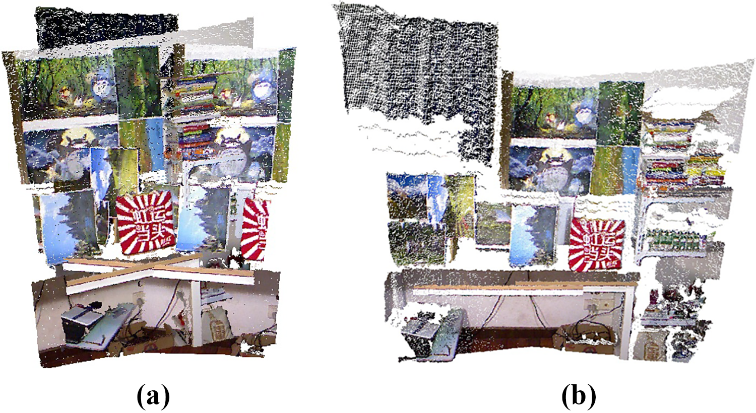
Alignment result of two point clouds with 50% overlap using GICP (a) and the proposed method (b).
Construct the depth and color panorama
If there are M RGB-D sensors in a vision system, take the coordinate system of a color camera in a random RGB-D sensor as the reference, the transformation matrix
Let
Furthermore, a depth panorama and a color panorama can be obtained by projecting textured 3-D points to a compositing surface. The usual choice for compositing a panorama with large FOV is to use a cylindrical or spherical projection. Figure 4(a) and (b) shows the cylindrical depth and color panorama obtained by projecting the panoramic point cloud in Figure 3(b) to a cylindrical surface with a bottom radius of the average focal length of the color cameras in the two RGB-D sensors. Note that both color images and depth images are well-aligned.

(a) Depth panorama and (b) color panorama that are constructed from (c) and (d) a pair of depth images and (e) and (f) a pair of color images.
Experimental results
System setup
Figure 5(a) shows the CAD design figure of the mounting rig that multiple RGB-D sensors are to be attached. Figure 5(b) shows the top view of the CAD model; the mounting angle of neighboring RGB-D sensors is 30°. Figure 5(c) shows the setup we built to verify the proposed approach of constructing the depth and color panorama. The setup consists of 12 Kinect v1 RGB-D sensors; all RGB-D sensors are placed vertically for a more compact design. The vertical FOV of a Kinect v1 RGB-D sensor is 43°. Thus, the overlap FOV of two neighboring RGB-D sensors is 13°

(a) The CAD design figure of the mounting rig that multiple RGB-D sensors are attached. (b) Top view of the CAD model, the mounting angle between neighboring RGB-D sensors is 30°. (c) The real setup used in this study for evaluating the proposed method composed of 12 Kinect v1 RGB-D cameras. (d) A distributed capturing system consisting of a gigabit switch and 12 low-cost Raspberry Pi single board computers.
Figure 5(d) shows a distributed capturing system that we built to capture depth and color images from multiple RGB-D sensors. The distributed capturing system is composed of a gigabit switch, 12 low-cost Raspberry Pi single board computers, and a laptop (which is not presented here). Each single board computer is connected with a Kinect v1 RGB-D sensor and is used to capture the depth and color images from an RGB-D sensor and send the frame data to the laptop through the gigabit switch using User Datagram Protocol. One pixel in the depth frame and the color frame has a size of 2 bytes and 3 bytes, respectively. Thus, when both the depth image and the color image from one RGB-D sensor are set to a size of 640 × 480, the total size of RGB-D frames from all 12 RGB-D sensors is 17.58 million bytes, which can be sent to the laptop through the gigabit switch at 7 fps. Decreasing the size of RGB-D frames can increase this frame rate, for instance a frame rate of 28 fps can be achieved when the size of RGB-D frames is set to 320 × 240.
Evaluation metrics and results
During the estimation of the transformation matrix T between a pair of RGB-D sensors, M pairs of matched 3-D points
The BPE estimates the 2-D alignment error between
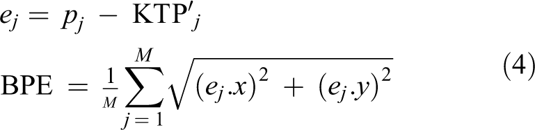
The 3AE is used to estimate the alignment error of matched 3-D points which can be calculated as follows

We used the setup in Figure 5 to capture 12 pairs of depth and color images to calculate the average value of BPE and 3AE. While extracting matched SURF key points, the distance threshold that is used to select well-matched key points is set to two times the minimum distance threshold of detected matched SURF key points. The re-projection error threshold is set to 0.1 pixel to refine selected matched 2-D key points. The values of BPE and 3AE for each pair of RGB-D sensors and the average value of BPE and 3AE are given in Table 1. The average BPE and 3AE is 1.1 pixels and 3.97 mm, respectively. When intrinsic parameters of multiple RGB-D sensors are estimated using the chess board-based method, optimum value of BPE and 3AE are 1.4 pixels and 3.8 mm, respectively, which show a slight difference.
BPE and 3AE of the estimated poses of 12 pairs of RGB-D cameras.a

BPE: Back-projection error; 3AE: 3-D alignment error.
a“Before” and “After” indicate the number of matched key points before and after applying the random sample consensus (RANSAC)-based filtering method, respectively.
The whole calibration process costs an average of 109 ms to calibrate a pair of RGB-D cameras, most of the time is spent extracting matched key points. When the calibration is done, depth and color images that are captured from multiple RGB-D sensors can be stitched into the depth and color panorama using estimated transformation matrices between multiple sensors. Figure 6 shows a 360° FOV color panorama and depth panorama. In the color panorama, some pixels are missing because of the corresponding depth values are invalid in depth maps. Note that there is no obvious misalignment in both the color panorama and the depth panorama. The depth values of objects in the depth panorama are continuous.

360° FOV (a) color panorama and (b) depth panorama that are constructed using the proposed stitching method. FOV: field of view.
It costs an average of 3.5 ms to stitch a depth image and a color image into the depth panorama and the color panorama. The frame rate of stitching 12 pairs of depth and color images with the same size of
In comparison, the calibration method in the study by Fernandez-Moral et al., 14 which is proposed to use plane patterns to calibrate multiple RGB-D sensors, got an ICP residual (3AE) of 2.9 mm. However, 200 images were captured to extract enough planes for calibration that costs much more time than our method.
Hengyu Li et al. proposed to use transformation matrices that are estimated only from color images to stitch depth and color images. 10 The method can generate a well-aligned depth and color panorama. However, estimated transformation matrices in the study by Li et al. 10 are depth-dependent, which means that when distances between objects and vision systems change, transformation matrices have to be reestimated. Depth maps are processed the same as color images while stitching 10 in that only positions of pixels are adjusted, the values of pixels are not changed. Although objects in depth maps are also aligned, the depth values of the same objects are discontinuous in the depth panorama. Figure 7 shows depth panoramas constructed using the method in the study of Li et al. 10 (Figure 7(a)) and the proposed method (Figure 7(b)). The depth values within the blue rectangle (the overlapping region) in Figure 7(a) are discontinuous. In contrast, depth values within the blue rectangle in Figure 7(b) remain continuous. Transformation matrices that are estimated in our method contain rotation matrices and translation matrices, which are depth-independent. Thus, once the calibration is done, transformation matrices can be used to stitch the depth and color panorama of scenes in which objects are in different distances, and the depth values of the same objects in the depth panorama can also remain continuous.

Comparison of the depth panorama constructed using (a) the method in the study by Li et al. 10 and (b) the proposed method, respectively. The blue rectangle in each panorama indicates the overlapping region between two source depth maps.
Conclusion and future work
In this article, a new method that estimates transformation matrices between multiple RGB-D sensors by constructing matched 3-D points using both depth images and color images is proposed to stitch depth and color images into the depth and color panorama with extended FOV. A multi-camera setup together with a capturing system was built to capture multiple depth and color images to evaluate the proposed method. Experiments verified the accuracy and efficiency of the proposed stitching method. The proposed stitching system can provide the depth and color panorama in real time.
In the future work, we will design a more compact multi-camera setup by designing an integrated circuit capture depth and color images from multiple RGB-D sensors instead of using a stack of single board computers. The more compact design that generates a depth and color panorama with extended FOV will be used to accelerate the reconstructing of indoor scenes and facilitate the sensing of moving robots.
Footnotes
Declaration of conflicting interests
The author(s) declared no potential conflicts of interest with respect to the research, authorship, and/or publication of this article.
Funding
The author(s) disclosed receipt of the following financial support for the research, authorship, and/or publication of this article: This research was funded by the National Natural Science Foundation of China (grant number 61305106), the Shanghai Natural Science Foundation (grant numbers 17ZR1409700 and 18ZR1415300), the basic research project of Shanghai Municipal Science and Technology Commission (grant number 16JC1400900), and the Shandong Provincial Natural Science Foundation (grant number ZR2017BF021).