
Abstract
This article concerns the problems of a defective depth map and limited field of view of Kinect-style RGB-D sensors. An anisotropic diffusion based hole-filling method is proposed to recover invalid depth data in the depth map. The field of view of the Kinect-style RGB-D sensor is extended by stitching depth and color images from several RGB-D sensors. By aligning the depth map with the color image, the registration data calculated by registering color images can be used to stitch depth and color images into a depth and color panoramic image concurrently in real time. Experiments show that the proposed stitching method can generate a RGB-D panorama with no invalid depth data and little distortion in real time and can be extended to incorporate more RGB-D sensors to construct even a 360° field of view panoramic RGB-D image.
Keywords
Introduction
Depth information is an important complement for computer vision applications based on visual (RGB) information. Traditional depth sensors include time-of-flight cameras, laser range scanners, structured light scanners, and binocular cameras. Another type of depth sensor is an infrared based sensor, such as the Microsoft Kinect, which generates a depth map by matching a dot in an infrared image with a dot in a precalibrated infrared pattern. 1 Compared with laser scanners and binocular cameras, the Kinect is much cheaper and can generate a reliable depth map at much higher speed. 2,3 Kinects have been widely used as primary 3D sensors in computer vision applications, such as detection, segmentation and recognition of objects, 4,5 3D modeling, 6,7 and simultaneous localization and mapping (SLAM). 8 However, a major limitation when utilizing Kinects in these applications is the narrow field of view of the Kinect, which limits the coverage of more objects in scenes. 3,9 The depth camera of the Kinect has a horizontal field of view of 57°, which is much smaller than the 240° field of view of the Hokuyo URG-04LX-UG01, a laser scanner with similar maximum range and accuracy to the Kinect. 3
To extend the sensing area of a single Kinect, combinations of Kinects have been used in 3D reconstruction 10,11 or 3D detection. 12–14 In these studies, several Kinects were placed to face the same object or to observe the same scenario to cover all sides of the model and avoid depth shadows caused by occlusion. Instead of placing Kinects to face inward, they can also be placed to face outward to extend the limited field of view through image stitching; this is the purpose of our work. Song et al. 15 provided a solution to extend the field of view by using a precalibrated rotated top–bottom arrangement of two Kinects; in this method, two depth maps were perspectively transformed to a common frontal flat reference coordinate to form a panoramic depth map by use of the homography between depth maps. Although the depth maps can be stitched seamlessly, the depth panorama is greatly distorted, since for larger fields of view we cannot maintain a flat representation without excessively stretching pixels near the border of the image. 16
To generate a depth panorama with little distortion and a large field of view, cylindrical or spherical projection is usually chosen. Each input image is warped to a cylindrical or spherical plane according to an estimated 3 × 3 camera matrix or homography. 16 This problem is well addressed by the work of Brown and Lowe, 17 in which the camera matrix was estimated and refined based on matched scale-invariant feature transform (SIFT) features between input color images. However, since depth maps lack SIFT features that can be extracted, this estimation method cannot be directly applied to depth map registration. In this study, we found that by aligning a depth map with a color image, the registration matrix of color images can be used to register depth maps. The problem of registering depth maps is transformed to the problem of registering color images. It can also be found that if the scenes around cameras do not change much, the registration matrixes do not need to be updated once they have been successfully estimated; this saves much time in estimating these matrixes and makes real-time stitching method possible. We also describe an efficient anisotropic diffusion based method to recover invalid depth data in the depth map obtained from the Kinect.
Method
In this section, the pipeline and implementation details of the proposed real-time RGB-D images stitching method are described. The proposed RGB-D images stitching method is outlined in Figure 1. The stitching method consists of three modules: depth map preprocessing, registration, and compositing. To register depth maps that lack feature points, the main idea of the proposed RGB-D images stitching method is to use the registration data from color images to register depth maps. The main purpose of the preprocessing module is to align the depth map with the color image so that the registration data of color images can be applied to the depth map registration. The registration module calculates registration data of color images that contain the relative rotation matrixes between pairs of captured color images based on the matched feature points. Finally, the registration data are fed into the compositing module to construct the RGB-D panorama. The registration module takes most of the time in this process; once the registration data are initialized, the registration module can run in a background thread, making real-time stitching possible. Constructing depth and color panoramas in parallel further accelerates the construction speed of the RGB-D panorama. The implementation details will be discussed in the following sections.

Proposed RGB-D image stitching method.
Suitable layout of two Kinects to extend field of view
Different layouts of the two Kinects will influence the amount of invalid depth pixels in each depth map and the total field of view of the stitched RGB-D panorama because of the interference between Kinects. Therefore, the suitable layout of the two Kinects must first be determined. There are mainly two categories of layout of two Kinects: side by side layout and superimposed layout. Depending on the included angle θ between Kinects, there are different types in each category, as shown in Figure 2. Through experiment, it was found that the side by side layout shown in Figure 2(c) and the superimposed layout in Figure 2(e) provide a similar widest field of view, which is almost twice the original field of view. However, since the two Kinects shown in Figure 2(c) have a greater overlapping area than those in Figure 2(e), this causes serious interference between Kinects, which causes more invalid data in the captured depth map, 18 as shown in Figure 3. Thus, we selected the superimposed layout shown in Figure 2(e) for our RGB-D image stitching.

Different layouts of two Kinects: (a–c) side by side, (d, e) superimposed.
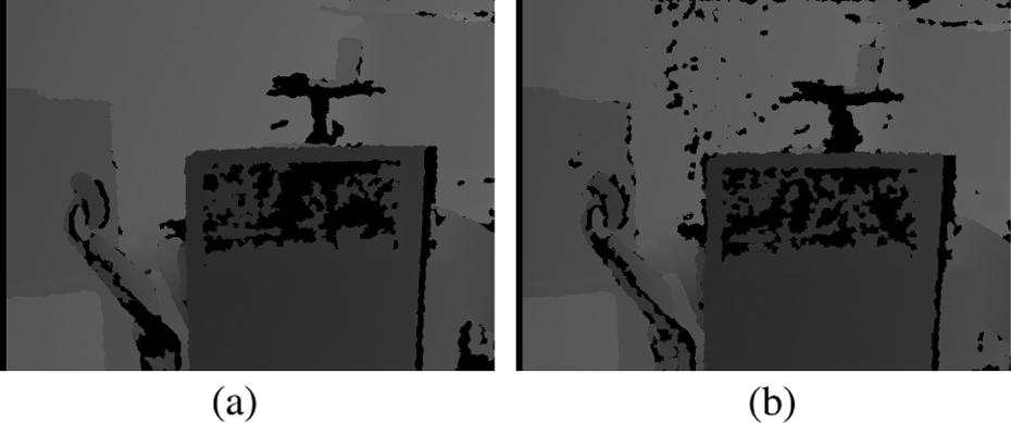
Interference between Kinects: (a) depth map from one Kinect; (b) depth map contains more holes because of interference between Kinects.
Depth map preprocessing
Align depth map with color image
To align the depth map with the color image, the relationship between them must be derived. Assume that the coordinates of a 3D point are denoted

Let p = [u, v,1]T denote the coordinates of the projection point of the 3D point in the image plane. According to a pinhole camera model, 19 , p and P are related by H, the intrinsic matrix of the camera, which is composed of the focal length parameters fx and fy, and the coordinates of the principal point u0 and v0, as seen in equation (2)

Applying equations (1) and (2) to the color and depth camera of the Kinect, we have


where Zdepth is the original depth value in pdepth in the Kinect depth camera coordinate system and Zcolor is the aligned depth value of Zdepth in pcolor in the color camera coordinate system. By simplifying equations (3) to (6), we obtain the relationship between the aligned depth map and the original depth map


where r and t are the rotation matrix and translation matrix that relate the depth camera coordinate system to the color coordinate system, which can be obtained by calibrating the Kinect depth and color cameras. Figure 4 shows the alignment result of the depth map using this method. From Figure 4(d) and (e), it can be seen that the depth map is aligned well with the color image. It is also worth noticing that there are fewer invalid depth pixels in the aligned depth map in Figure 4(c) than in the original depth map in Figure 4(b). This is a beneficial step for the following depth map hole-filling process.
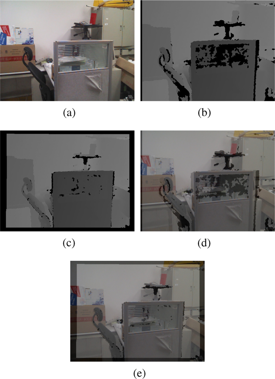
Alignment of depth map and color image: (a) color image, (b) raw depth map, (c) aligned depth map, (d) mixture of color image and raw depth map, (e) mixture of aligned depth map and color image.
Depth map hole filling
The depth map generated by the Kinect is very noisy and many regions have invalid depth data, shown as black holes, owing to multiple reflections, transparent objects, and scattering from certain surfaces. 9 To generate depth panorama without black holes, the depth map must be processed to recover invalid depth values before being fed into the compositing module. The anisotropic diffusion method was first used to refine the Kinect depth map by Vijayanagar et al., 20 who generated satisfying results without taking a lot of time. The proposed method is also based on the anisotropic diffusion method but there are two main differences: the anisotropic diffusion filter is just applied to the depth map of original size and the conduction coefficients are only computed from the depth map. Following the work of Perona and Malik, 21 considering the anisotropic diffusion equation for image I as

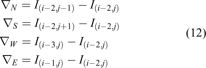
where div is the divergence operator, ∇ and Δ are the gradient and Laplacian operators, respectively, with respect to the space variables, and c(x, y, t) is the conduction coefficient. For image I with its origin on the top left corner, where i and j indicate the column index and row index, respectively, the discrete form of equation (9) can be given by
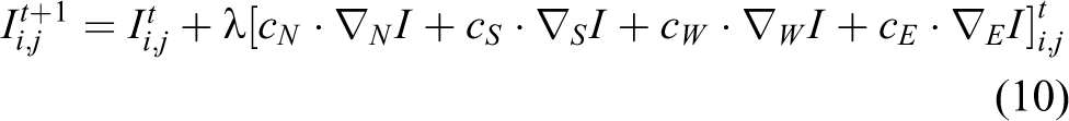
where 0 ⩽ λ ⩽ 1 for equation (10) to be stable, and ∇I are the nearest-neighbor differences. The conduction coefficient c is selected as

where K can be a fixed value set by hand. When the anisotropic diffusion filter is applied to fill depth holes, since Ii,j has a depth value of zero, we replace
The filled depth map of Figure 4(c) obtained through this method can be seen in Figure 5(b). The result shows that the proposed method can generate satisfying results.

Depth map hole filling using anisotropic diffusion: (a) cropped depth map from Figure 4(c); (b) filled depth map using the proposed hole-filling method.
Registration and compositing
After aligning the depth map with color image, the problem of registering the depth maps can be transformed to the problem of registering color images. The robust feature based color image registration method of Brown and Lowe 17 is used to calculate the registration data in the proposed method. Briefly, the SIFT feature points are first extracted and, based on matched feature points between pairs of images, rough camera parameters represented by homography are calculated. Then the bundle adjustment method is used to refine these camera parameters to generate registration data globally; the data are represented as a combination of rotations and focal lengths. Notice that it takes much longer to calculate the registration data than to construct the RGB-D panorama. For a scene without much change, the registration data do not need to be updated in real time. Thus, in the proposed RGB-D image stitching method, the time-consuming registration data calculating module is updated in a background thread and the main thread is used to construct the depth and color panorama concurrently, to ensure real-time stitching. In the compositing process, a spherical warper is used to map depth and color images onto the spherical compositing surface and a multiband image blender to construct the final RGB-D panorama.
Experimental results
In this section, the proposed real-time RGB-D image stitching method is verified by experiments. The adopted superimposed layout of the two Kinects is shown in Figure 6. the included angle between Kinects is 50°.

Superimposed layout of the two Kinects: (a) front view, (b) top view.
By using the standard stereo camera calibrator algorithm, the intrinsic parameters and relative position of color and depth camera of the two Kinects can be obtained. Figure 7 shows two pairs of color and depth images from a real scene that were captured to test the validity and efficiency of the proposed RGB-D image stitching method. Notice that there are many invalid depth pixels within the rectangles drawn in Figure 7(c) and (d). These depth holes are caused by the transparent glass board, as can be seen within the region of rectangle shown in Figure 7(a) and (b), which can be used to verify the validity of the proposed depth map hole-filling algorithm. In our experiments, the method is implemented through C++ programming based on Open Source Computer Vision (OpenCV) and is tested on a computer with a 3.4 GHz central processing unit and 16GB RAM. Both the color and depth images are captured at a size of 640 × 480 pixels.

Color and depth images from a real scene: (a) color image from Kinect 1; (b) color image from Kinect 2; (c) raw depth map from Kinect 1; (d) raw depth map from Kinect 2.
The aligned depth maps are shown in Figure 8(a) and (b); Figure 8(c) and (d) show the filled depth map. The result of the stitched depth map is shown in Figure 9(a). It can be seen that the depth panorama contains no invalid depth pixels and aligns precisely with the corresponding color panorama in Figure 9(b). The field of view of the constructed RGB-D panorama is almost twice as large as the field of view of the original depth and color image from a single Kinect. The depth panorama constructed using the the method of Song et al. 15 is shown in Figure 9(c).

Preprocessed depth maps: (a) aligned depth map of Kinect 1; (b) aligned depth map of Kinect 2; (c) filled depth map of Kinect 1;(d) filled depth map of Kinect 2.

Stitching result of a real scene using the proposed method: (a) stitching result of depth maps; (b) stitching result of color images; (c) stitching result using method proposed by Song et al.15
To compare the results on distortion between Song’s method and the proposed method, image quality indexes of the peak signal-to-noise ratio and the Mean Structural Similarity algorithm were calculated. When calculating values of the two indexes, the ground truth depth maps in Figure 7(c) and (d) were used as the reference images; image regions of the same size cropped on the left and right from the result of Song’s method and our method were evaluated and compared. To be fair, the depth hole-filling process was not applied in our stitching process. From the evaluation results in Table 1 we can see that the stitching result of the proposed method obtains a higher score; this means that the constructed panorama of the proposed method is less distorted. The registration module took 274 ms to update the registration data and 41 ms to construct the RGB-D panorama, the speed was up to 25 fps.
Objective assessment of stitching result using method of Song et al. 15 and proposed method.

Furthermore, the proposed stitching method can be easily extended to incorporate more pairs of Kinects to generate RGB-D panoramas with a larger field of view. Figure 10 shows the time consumption of registration and the compositing module when more pairs of Kinects are incorporated. Notice that when six pairs of Kinects are incorporated to generate a RGB-D panorama with a 360° field of view the proposed method can still operate at 4 fps. Figure 11 shows an example in which three pairs of Kinects are used to construct a RGB-D panorama with an almost 300° field of view. For visual salience, the depth map is shown using HSV (hue, saturation, value) color space. Figure 12 shows the layout of the three pairs of Kinects.

Consumption time of registration and compositing with respect to the number of pairs of Kinects.

RGB-D panorama constructed by the proposed stitching method using three pairs of Kinects.

Layout of three pairs of Kinects to generate RGB-D panorama.
As the number of pairs of Kinects increases, it will be difficult to capture and stitch RGB-D images in a single computer and the synchronization problem must be considered. We recommend the use of a router to establish a simple local area network that includes a number of low-cost single-board computers, such as the Raspberry Pi, and a high-performance computer. Single-board computers are used to capture color and depth data from each Kinect and send the data to a high-performance computer through cables based on the User Datagram Protocol in real time. The high-performance computer is used to receive image data from several channels in real time and implement the stitching algorithm.
Conclusions and future work
This article has presented a real-time RGB-D image stitching method to extend the limited field of view of the depth map of Kinect-style RGB-D sensors. The main idea is to use registration data of color images to construct depth and color panorama. This has several advantages over previous approaches. Firstly, by aligning the depth map with the color image, the registration data calculated by registering color images can be used to construct a spherical depth panorama with little distortion. Secondly, by using a background thread to update registration data, the compositing module in the main thread can construct depth and color panorama in real time concurrently. Thirdly, the stitching method can be easily expanded to incorporate more Kinects to extend the field of view of the depth and color map to any degree and even a 360° panorama. An efficient anisotropic diffusion based method is also proposed to recover invalid depth data in the depth map from the Kinect. One limitation of the proposed method is that the update period of registration data is slow, which will cause a distorted panorama when fast-moving objects come across the overlapped regions between pairs of color and depth images. Our current and future work aims to speed up the registration and compositing module using a graphics processing unit, to add a module to detect moving objects, so as to make the stitching method more robust to the change of environment, and to apply this RGB-D panorama capturing system to applications such as SLAM and 3D modeling.
Footnotes
Acknowledgements
The authors gratefully acknowledge the helpful comments and suggestions of anonymous reviewers, which improved the presentation.
Declaration of conflicting interests
The author(s) declared no potential conflicts of interest with respect to the research, authorship, and/or publication of this article.
Funding
The author(s) disclosed receipt of the following financial support for the research, authorship, and/or publication of this article: This work was supported by the Key Projects of the National Natural Science Foundation of China (grant number 61233010), the National Nature Science Foundation of China (grant numbers 61305106 and 61403245), and the Shanghai Municipal Science and Technology Commission Project (grant number 14JC1491500)