
Abstract
Recent advancements in deep learning require a large amount of the annotated training data containing various terms and conditions of the environment. Thus, developing and testing algorithms for the navigation of mobile robots can be expensive and time-consuming. Motivated by the aforementioned problems, this article presents a photorealistic simulator for the computer vision community working with omnidirectional vision systems. Built using unity, the simulator integrates sensors, mobile robots, and elements of the indoor environment and allows one to generate synthetic photorealistic data sets with automatic ground truth annotations. With the aid of the proposed simulator, two practical applications are studied, namely extrinsic calibration of the vision system and three-dimensional reconstruction of the indoor environment. For the proposed calibration and reconstruction techniques, the processes themselves are simple, robust, and accurate. Proposed methods are evaluated experimentally with data generated by the simulator. The proposed simulator and supporting materials are available online: http://www.ilabit.org.
Introduction
The indoor reconstruction is a crucial technique in computer vision (CV), contributing to various applications such as virtual and augmented reality, 1,2 layout recovery, 3,4 and mobile navigation. 5–7 Perception and sensing become an important part of the reconstruction of unknown environments. In general, reconstruction methods can be based on passive or active sensing techniques; each method has its own relative merits.
Passive vision systems do not rely on energy being emitted into the scene. 8 –13 This type of sensing technique operates similar to human vision and the hardware requirements are modest (e.g. stereo vision). They do, however, suffer from particular difficulties, such as point extraction in nontextured environments, correspondence problem, low accuracy, and speed. 14 Therefore, the reconstruction of indoor environments with simple corridors can be time-consuming and not as accurate as expected.
In contrast to the passive vision systems, the active vision systems may rely on energy (e.g. structured light) being emitted into the scene. This type of sensing technique may overcome or alleviate problems existing in passive vision systems. In this case, one of the cameras is replaced by an external projecting device (e.g. laser emitter), and the emitting light is detected by the remaining cameras. 14 Important here is the calibration between the camera and the laser source in order for the measurement result to be as accurate as required.
Besides sensing techniques, another performance indicator of the indoor reconstruction is the field of view (FOV). Normal or even wide-angle charge-coupled device cameras still have relatively modest FOVs, limiting the reconstruction of the whole scene. For example, the ceiling is not usually visible 15 and yet it is an important component of the main structure of the indoor environment. Therefore, the aim of recent research is to improve the situation by extending the FOV by deploying omnidirectional cameras. In view of the aforementioned developments, this article considers a more universal, low-cost vision system, which improves three-dimensional (3D) reconstruction results for a wide range of indoor scenarios.
In the article, 16 it was shown how useful a simulation environment can be for comparative analysis between methods. In this article, we also take advantage of it when comparing 3D reconstruction methods. Additionally, in this article, we decided to go further and ensure open access to our simulator so as to provide the opportunity for other scholars to test their theories and conduct experiments with omnidirectional vision systems. Our simulator runs on Windows, macOS, and Linux.
The contributions of our work are three-fold: (1) A customizable photorealistic simulator for the CV community working with omnidirectional vision systems with the structured light in indoor scenarios. As a consequence, two practical applications are studied within the proposed simulation environment: (2) An improved extrinsic calibration of an omnidirectional camera and a laser plane is proposed. (3) A 3D reconstruction method for omnidirectional vision system based on structured light in combination with semantic segmentation. The proposed approach raises the possibility of reconstructing environments with a single-image capture. Simulation results have proven to be are accurate and robust for various indoor scenes.
The remainder of this article is presented in five sections. The second section reviews the related work. The third section provides a simulator overview. The fourth section is the proposed calibration approach. The fifth section is the proposed 3D reconstruction approach. Finally, the conclusion is drawn in the sixth section.
Related work
This article presents a novel reconstruction method for indoor scenes on a basis of the omnidirectional vision system with structured light. The reconstruction method is tested by means of the proposed simulator. The distinctive advantage of our method is that with a single capture from the camera, it is possible to recover both depth (employing data from the structured light) and the structure of the indoor environment (by semantic segmentation). However, before moving to the reconstruction method itself (“3D reconstruction of indoor environments” section), two preliminary steps related to the simulation environment should be considered. The section “Simulator” presents the simulation environment and reveals its capability. The section “Calibration of the vision system” is the proposed method for extrinsic calibration between vision sensors.
Simulator
In real experiments, there is a measurement uncertainty, which makes the comparison between methods more complicated. Moreover, in real cases, it is difficult or not possible to estimate real values of some of the parameters, for example, real location or orientation of the laser plane, whereas inside the simulation environment, they are known. In the last few decades, a wide variety of robotic simulators have been developed commercially or in research laboratories, 17 resulting in considerable publication in this area. An exhaustive review is beyond the scope of this article, so this section considers only those most relevant to our article, namely the simulators supporting omnidirectional cameras and structured light. Widely used simulators as Gazebo 18 and USARSim 19 support laser plugins but unfortunately, they do not include omnidirectional cameras. In contrast, in works, 20,21 authors managed to integrate omnidirectional cameras to these simulators. Authors superimposed images of the environment onto the faces of a cube, after which they were able to use this as a texture for creating a hyperbolic mirror or a fisheye camera. However, such manipulations require certain programming skills that could be problematic for some users. In recent years, NVIDIA released the photorealistic robotics simulator, namely NVIDIA Isaac Sim, 22 and the latest version of this simulator supports a fisheye camera. However, the use of this simulator is limited to computers with NVIDIA GPUs. Multiple platforms support is provided by programs such as blender and unity.
To generate photorealistic synthetic images, in a couple of works, blender was considered as the basis for the creation of omnidirectional vision systems. 23,24 Blender is an open-source suite of tools for 3D modeling, rendering, and animation. However, it is not suited to programming tasks and communication with other programs, which restricts its use in certain cases. More flexibility is provided by game engines (e.g. unity), which support both programming opportunities as well as realistic graphics and physics. By taking an advantage of modern game engines, Bourke released a publicly available fisheye camera within unity, 25 supporting a variable FOV. Therefore, development based upon the unity platform may capture omnidirectional images of their 3D scenes. This camera model was also considered in Kholodilin et al. 16 The authors demonstrated that modern game engines (e.g. unity) allow users to create photorealistic virtual environments that are suitable for testing theories before experiments are performed in real conditions. However, the process of developing a new scene is time-consuming and requires certain skills in unity. To facilitate research in this field, in this work, we decided to release the simulator, supporting the omnidirectional camera and the structured light to the CV community. The simulator has a developed user interface and customizable sections. Therefore, it can be used independently of unity. To the best of our knowledge, this is the first customizable simulator, which targets the study of the omnidirectional vision system with the laser illumination in indoor environments. No particular skills in unity are required to use our simulator and it is installed in the same way any other standard gaming application. If the functionality of the built version of the simulator is insufficient, then the full unity project is made available for users to modify to suit their specific needs.
Calibration of the vision system
The calibration process was analyzed in Kholodilin et al., 16 and it focused on the calibration procedure itself and the verification of the calibration results by mapping. However, the configuration of the vision system proposed in Kholodilin et al. 16 is not suitable for the 3D reconstruction tasks, because the camera is located parallel to the floor. As a result, part of the walls and the whole ceiling were out of the FOV of the camera. In this article, we propose a vision system in a different configuration and technique for its extrinsic calibration. A configuration with the camera located perpendicular to the floor provides visibility of all elements of the indoor environment. With respect to the calibration, we demonstrate that the proposed calibration technique provides more flexibility without loss of reliability and robustness.
3D reconstruction of indoor environments
Numerous approaches have been proposed for the 3D reconstruction of the indoor environment. For example, a digital representation of the scene can be generated with 3D point clouds from a series of images. 6 By considering common features between images is possible to determine camera poses (Bundler) and subsequently, 3D point clouds can be created. The performance of these methods depends on being able to reliably detect features in the surroundings; therefore, methods based on the passive vision systems may fail for featureless, or for example, dark and reflective environments.
Another approach to creating a digital representation of the scene is to use depth cameras such as Microsoft’s Kinect. 26,27 However, a key limitation of the Kinect sensor is the limited FOV. In an attempt to address these deficiencies, Tsai et al. presented a vision system with multiple RGBD (Kinect) and digital single-lens reflex cameras. 28 By merging the conventional images with the depth images, authors were able to reconstruct the environment even in featureless areas. From the results presented in their work, it can be seen that even if multiple sensors are involved, there can still be unreconstructed regions. This makes the method less applicable in certain applications, for example, mobile navigation. This problem might be solved by integrating even more vision sensors to the system, but this increases the computation and overall expense of the vision system.
A wide horizontal FOV can be achieved by replacing several Kinect sensors with a light detection and ranging (LiDAR) sensor. 6 This involves fewer elements in the vision system, making it more reliable, but still, a single LiDAR unit generally provides insufficient vertical information. At the same time, vision systems with multiple LiDARs are problematic due to their cost, size, and weight. Several approaches based on a single LiDAR sensor have attempted to address this problem. 28 –32 The general idea of these works, which provide a cost-effective vision system and achieve a wide vertical FOV, is that authors have attempted to shift from rigid vision systems to more flexible configurations by rotating the LiDAR sensor. This makes it possible to extract more features of the environment with a single LiDAR unit. Even though these LiDAR-based approaches provide a fully omnidirectional depth-sensing capability, they are still a relatively costly sensor for the indoor environment. A more cost-effective and lightweight solution is achieved by using a structured light approach.
A structured light solution is not only cost-effective and lightweight but it also allows easy detection of projected features by the camera and the subsequent calculation of depth information from laser triangulation. This approach provides a wide FOV while achieving portability and affordability. Son et al. proposed a tiny palm-sized vision sensor, which is composed of a fisheye camera, structured light, and rotating motor. With the rotational movement, a 3D omnidirectional sensing capability is achieved. 33 Particular attention needs to be made to the type of encoder used, for example, magnetic encoders may suffer from nonlinearity problems. Additionally, angular position measurement error may adversely affect the reconstruction results. De Ruvo et al. also proposed the vision system based on a rotation platform. 34 By ensuring accurate control of the angular velocity, the authors achieved a high precision 3D omnidirectional reconstruction. However, this type of vision system has a relatively large and complex structure, which is challenging to recreate. Moreover, both methods described above are focused on a single reconstruction and the reconstructed models are not textured. To overcome this problem, Lian et al. proposed an omnidirectional vision system where a vertical laser sensor acquires the geometrical data. 7 The authors then merged the reconstruction results with the textured data captured by the omnidirectional camera. However, the reconstruction process of the whole environment would be time-consuming as additional movements of the mobile robot are required. To reduce the reconstruction time, it is necessary to consider other approaches.
The recent advancements in deep learning have been applied to research on structure reconstruction of indoor scenes, for example, layout recovery from panoramic images. 3,4 In doing so, it is possible to generate the 3D structure of an indoor scene from an image captured from a single position in space. The main limitation is that the depth data are not involved in the reconstruction procedure. The process of creating a reliable 3D digital model of the indoor environment with less input data from the vision sensors is still an active area of research.
Simulator overview
Need for simulation
One of the main goals of our simulation environment is to provide researchers and engineers greater opportunities when testing theories and algorithms involving omnidirectional vision systems. Our simulation solution enables algorithms without the need to simultaneously acquire the hardware. Moreover, empowering omnidirectional vision systems with CV capabilities (e.g. simultaneous localization and mapping, path planning, and semantic segmentation) is becoming an increasingly important research direction in the field of mobile robots. However, in real-world applications, it might be difficult or even impossible to generate ground truth data for comparative analysis with the experiment data. The following issues may influence the ground truth data generation: the drift of mobile robot wheels, noise and drift of sensors, the accuracy of the semantically labeled data, measurement uncertainty, and so on. Taking into account all the abovementioned issues, we built a high-fidelity simulation environment, which is aimed at bridging the gap between simulation and reality, at the same time making it relevant for CV researchers and engineers. Our simulation environment allows experiments to be performed in a cost-effective way in comparison to real experiments. It is easier to set up, works faster, and is more convenient to use than physical experiments. With the proposed simulator, it is also possible to generate depth data, semantically labeled data, and path data, which can be tested within the photorealistic simulated indoor scenarios. This opens up new opportunities for evaluating performance across a diverse set of experiments.
Individual features
The proposed simulator can be simply installed and configured on Windows, macOS as well as the Linux operating systems. The simulator package includes (1) interaction with scenes and objects, (2) communication with other programs through transmission control protocol (internet protocol), and (3) fully implemented applications related to the calibration of the vision system as well as 2D/3D mapping. All these features allow researchers to configure their own experimental setups and design better algorithms for these purposes. An attempt has been made to create realistic scenes by using rendering capabilities such as light sources, reflections, and shadows. Figure 1 shows a snapshot taken by our simulator, illustrating these rendering capabilities.

Several modes are supported by the simulator. The image above shows ordinary mode. The image below shows semantic labeling mode and depth mode. The middle image shows zoomed sections of the main screen.
Capabilities
The simulator consists of several screens: simulation, calibration, and measurement. Simulation is the main screen where experiments take place (see Figure 1). Elements included in the simulation can be configured and controlled with the panels on the left and right. For example, changing the resolution of the camera, its FOV, activating/changing/moving objects, tracking of the mobile robot, and so on.
The calibration screen consists of a checkerboard pattern presented on a 3D panel as seen from the virtual camera point of view (whose location and resolution can be dynamically adjusted). The intrinsic calibration of the lens is achieved by interactively moving the camera or checkerboard pattern (see Figure 2). As with the simulation screen, it supports changing the resolution of the camera, its FOV, and changing the relative size of the checkerboard pattern.

The calibration screen.
The measurement screen includes the measurement tool, which is highlighted in yellow in Figure 3. By moving this tool, it is possible to measure distances from the camera to certain objects in the simulated scene; these may or may not be visible in the simulation screen. In Figure 3, this tool was moved to the laser strip associated with the sofa.

The measurement screen.
Calibration method
System model
The system model was previously described in Kholodilin et al. 16 and only a brief overview is presented in this section. The configuration of the proposed vision is different (the camera is rotated, see Figure 4) and how this difference affects the equations is explained in the following.

(a) Previous configuration and (b) proposed configuration.
World coordinates of the laser plane (X, Y, Z) can be obtained as follows

where u and v represent pixel coordinates and


where ai are coefficients; N is the degree; and points uc and vc are the center of the image.
The laser emitter has a rigid configuration, consequently the distance to the camera is constant: along the Z-axis in Figure 4(a) and along X-axis in Figure 4(b). Taking into account the aforementioned criteria, for the proposed vision system, equation (1) can be simplified as follows

Problem
In Kholodilin et al., 16 a novel calibration technique for obtaining extrinsic parameters between the camera and the laser plane was presented. This calibration method was based on the box target and proved its robustness in comparison with other calibration methods. This approach, however, contains some limitations, namely it is not suited to the configuration of the vision system considered in our current work as we lose part of the target (see Figure 4(b)) required for the calibration procedure. In this section, we consider an improved calibration technique and estimate its robustness in comparison with our previous calibration method.
Calibration procedure
The goal of the extrinsic calibration is to find parameters of the rotation matrix of the camera and the transformation matrix of the laser plane, respectively. In general form, this optimization problem can be formulated as follows

An improved calibration target was developed (see Figure 5) for solving the optimization problem described in equation (5). The main advantage of this target is its versatility as it can be applied to various configurations of a vision system. Another advantage is its flexibility as it can be simply placed in front of the mobile robot. The proposed target allows an extrinsic calibration to be performed by only capturing a single snapshot, and this procedure is explained in the following.

The proposed calibration target.
Extrinsic calibration of the camera
This section explains the process of obtaining parameters forming the camera rotation matrix Rc
as described in equation (5). To carry out the calibration process to obtain camera extrinsic parameters, first of all, pixel coordinates belonging to the border (between white and black regions) of the target are projected by equation (4) to the world coordinate system (see Figure 6(a)). After that for each parameter pitch, roll, and yaw, the optimization is described as a series of equations (6)–(8). The pitch is calculated when projected to the world coordinates vectors


(a) Projection with unknown pitch and roll and (b) projection with known pitch, roll, and yaw.
The yaw is calculated when projected to the world coordinates vectors
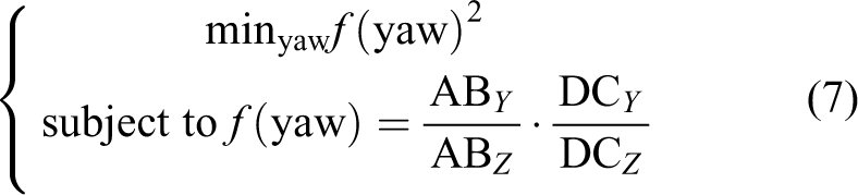
Once the pitch and yaw are known, it is possible to calculate the roll. The roll can be found by minimization of the slope of the vector

At this point, pixel coordinates belonging to the border of the target can be projected by equation (4) to world coordinates with the pitch, roll, and yaw determined during the calibration procedure (see Figure 6(b)). Once the camera is calibrated, we can move to the calibration of the laser plane.
Extrinsic calibration of the laser plane
This section outlines the process of obtaining parameters forming the transformation matrix

(a) Projection with unknown pitch, roll, and distance and (b) projection with known pitch, roll, and distance.
The pitch is calculated when projected to the world coordinates vectors

Another parameter related with the Rl
is the roll. The roll can be found by minimization of the slope of the vector

The last unknown parameter in the transformation matrix of the laser plane represents the distance to the laser plane. The real distance D 1 between the left and right sides of the target is known. The distance D 2 between the sides of the target can be found experimentally from the world coordinates of the laser. Thus, the variable representing the distance to the laser plane can be calculated as the difference between D 1 and D 2. This minimization problem can be written as follows

The pixel coordinates of the laser beam can now be projected by equation (4) to the world ones with the pitch, roll, and distance to the laser plane, determined during the extrinsic calibration (see Figure 7(b)).
Evaluation
Experimental setup
To evaluate the merits of the proposed calibration technique as well as to determine the relative quality and performance, it was compared with two other calibration methods. The experimental setup is similar to the one presented in Kholodilin et al. 16 and is depicted in Table 1. Method 1 is based on the box target and its calibration technique was considered in Kholodilin et al. 16 Method 2 is based on the checkerboard and its calibration technique was considered in Xu et al. 35 Firstly, the comparison of extrinsic parameters (Rc , Rl , Tl ) was based on the case where all calibration targets were visible (see Figure 8). Secondly, the performance of the calibration method was estimated for the configuration of the vision system considered in this article (see Figure 9). For this configuration, one side of the box target (method 1) was not visible, thus the proposed method was compared only with method 2. Thirty-five configurations of the vision system were included in the experiment, where parameters of the rotation matrixes of the camera and the laser plane were varied but did not exceed 10°.
The experimental setup.


Configuration of the vision system #1. (a) method 1, (b) proposed, and (c) method 2.

Configuration of the vision system #2. (a) Proposed and (b) method 2.
Results
Table 2 presents the mean absolute error and the root means squared error for the comparative analysis between the calibration methods. For configuration of vision system #1, method 1 showed better results, followed by the proposed method, and lastly method 2. For configuration of vision system #2, method 1 is no longer applicable; thus among the other two methods, the proposed method showed better results. It is also worthwhile mentioning that the proposed method is faster than method 2. The average run time among all configurations for the proposed method is almost 2.5 times faster than method 2. Maximum absolute error (AE) presented in Table 2 relates to the index of the particular experiment, which is presented in brackets. In “3D reconstruction” section for these particular configurations, a visual analysis is presented based on the 3D reconstruction.
The experiment results.

MAE: mean absolute error; AE: absolute error; RMSE: root mean squared error.
Discussion
In the article, 16 it was shown that for configuration of vision system #1, method 1 works better than method 2. The current work aims at evaluating the proposed method against other calibration techniques. It was assumed that by modifying the calibration target and calibration technique of method 1, it would be possible to achieve similar calibration results. Contrary to the expectations, the calibration results of method 1 were better than both other methods as depicted in Table 2. Thus, for configuration #1, it is better to use method 1. The experiment results of the proposed method are not as good as of method 1, but the proposed method is more universal and can be implemented for different vision system configurations. It is also worthwhile mentioning that for both configuration #1 and configuration #2, the proposed method showed better calibration results than method 2, which is based on the checkerboard patterns.
3D reconstruction method
Once the vision system was calibrated, we can consider the reconstruction of the 3D structure of the indoor environment. Our method includes several key steps, which are shown in Figure 10. First of all, interesting regions in the input image are segmented with semantic labels. Secondly, images of these objects are extracted and transformed so as to be imaged in a perspective projection. After that, the depth information is recovered based on the laser data. Finally, the 3D model is assembled. These steps are described in more detail in the following.

From a single fisheye snapshot to the 3D model of the indoor environment.
Semantic segmentation
One of the benefits of our simulator is that it can provide automatic ground truth labeling for the main parts of the scene (see Figure 10). The problem with the manual labeling is that the process itself is time-consuming as images may contain a wide range of elements, this is especially so for omnidirectional images. This section demonstrates the capacity of the automatic ground truth labeling by training a semantic segmentation network using deep learning.
Feature extraction
There are a variety of features for better image understanding, which, in general, can be named as hand-crafted features and learned features. Hand-crafted features are extracted manually using an algorithm defined by an expert. Learned features can be extracted with the use of convolutional neural networks (CNNs). 36,37
CNNs architectures are used in fields such as image recognition, image annotation, and image retrieval.. 38 As for image classification, CNN architecture consists of several convolutional layers followed by one or more fully connected layers. 39 Image feature extraction based on CNNs has demonstrated its effectiveness in a number of applications. 40 –42
In this article, the goal of the CNN is the detection of features of an indoor environment (floor, ceiling, walls, and doors) by labeling them with different colors (semantic segmentation). He et al. pointed out that the deeper the neural network, the more difficult it is to train it. 43 This problem was solved by using the residual learning framework, namely ResNet. Experimental results showed a better performance in training and testing on the ImageNet Large Scale Visual Recognition Challenge 2015 validation set with a top one recognition accuracy of about 80%. 43 An operating principle of a residual network is that residual functions (instead of unreferenced functions) with reference to the layer inputs should be learned by each layer of the network. These architectures are easier to optimize and it is possible to obtain improved accuracy by significantly increasing the depth. 43 Thus, these networks were considered in our work.
Experimental setup
The data set was generated by our simulator and contains 300 labeled images. About 80% of the data set was partitioned into training data and the remaining 20% was used as test data. This data set is composed of 240-by-240-pixel images and tested by two networks: ResNet18 and ResNet50. Networks were trained with the use of a single CPU with a clock speed equal to 2.5 GHz; 10G of RAM, and the graphics processing unit (GPU) was an Intel HD Graphics 4000, which has 1.5G memory. We used 64-bit macOS as the operating system.
Results
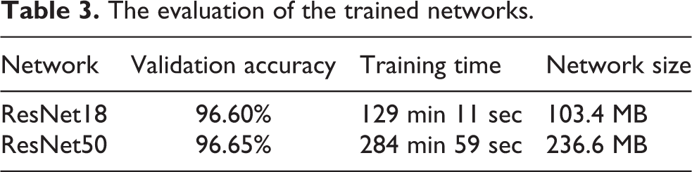
Figure 11 shows the behavior of the ResNets. Table 3 indicates that the performance of the ResNet18 is not inferior to ResNet50, but at the same time, it took less time to train ResNet18 and the network size is lower in comparison with ResNet50. Figure 12 shows some of the output results of the trained networks. By visual representation, it can be seen that both networks were trained in an accurate way by comparing with the ground truth.

Neural network performance evaluation. ResNet18 is shown in red color and ResNet50 is shown in blue color.

Training results.
The evaluation of the trained networks.
Discussion
It was demonstrated that the labeled data generated by our simulator are suitable for training neural networks. The automatic labeling itself can significantly simplify the process of collecting data for testing theories and verifying experiment results. It was also found that by using deep learning, the semantic segmentation network can be well-trained with a modest number of the network layers. This approach is additionally fast and does not increase the output network size.
Perspective projection
Preparation
Once the semantic segmentation network was trained, the portion of interest can be extracted from the input fisheye image. First of all, for every element (floor, ceiling, walls, and doors), masks are created (see Figure 10). It is worthwhile mentioning that the reconstruction method proposed in the article allows one to obtain the 3D model of the indoor scene within the visible region of the laser beam associated with the walls in the fisheye image (see Figure 10). Next, with the previously created masks and the working region of the laser beam, it is possible to extract the interesting portions of the scene (see Figure 13). Finally, when the elements of interest are extracted from the fisheye image, the perspective projections can be created.

Upper row shows extracted regions of the indoor environment (floor, ceiling, walls, and doors) with the visible laser beam. Lower row shows the corresponding perspective projection for extracted regions of the indoor environment.
Perspective projection
The process of creating the perspective projection image is performed in the reverse direction, that is, for every pixel (or subpixel for anti-aliasing) in the perspective image plane, one needs to find the best RGB estimate in the fisheye image.
The high-level process is as follows:

Initialization of the virtual camera.

Perspective image.

Rotate this vector P about the axes corresponding to roll, pitch, and yaw to orientate the perspective camera as desired, call this vector P′.
Calculate the angles ø and θ by equation (13), see Figure 16.

Transformation between world and camera coordinates.

Determine the image index (I, J) in normalized fisheye image coordinates given these

Transformation to the image coordinates.

where
Results of the perspective projection are shown in Figure 13.
3D reconstruction
Last step is related to the reconstruction of the indoor environment. For reconstructing the depth of the scene several steps are required. The image coordinates of the laser beam are extracted and distances to the corresponding walls and doors are calculated by equation (4). Once the location of the wall is known, it is possible to calculate distances to the floor and ceiling. Now, the labeled image regions between the parts of interest can be extracted as follows:
In a similar fashion to the laser plane, distances to the floor and ceiling can be successfully found by triangulation. The distance from the mobile robot to the particular wall along Y-axis is known and constant. Taking into account the aforementioned criteria, an equation for calculating world coordinates of the wall and ceiling can be written as follows

By our reconstruction method, it is also possible to reconstruct a corner. For this procedure, the endpoints of the laser beam have to be extracted. These endpoints are used to divide walls in a corner for two independent meshes. Then based on these endpoints, orientation for each of the walls in a corner is calculated. Finally, the 3D model can be assembled from the segmented parts of the scene in combination with the corresponding distances. Figure 18 shows individual reconstructed 3D models as well as a global map. Simulation results show that the proposed reconstruction technique provides accurate and robust 3D models for different configurations of indoor scenes. Results also show that by using a single-input image, it is possible to reconstruct not only the layout of the indoor environment but also the depth as well.

Reconstruction results (single reconstruction and global map are presented).
Table 2 presents indices associated with each particular experiment with the maximum AE. Figure 18 illustrates the corresponding 3D models for some of these configurations. The goal is to compare calibration methods with a visual analysis. For configuration 6, the reconstruction models are quite similar. However, from other configurations, it can be seen that reconstruction results are better for the proposed method.
Conclusion and future work
This article presents a photorealistic simulator applicable to various applications of CV. With the aid of the proposed simulator, two practical applications were studied, namely extrinsic calibration of the vision system and 3D reconstruction of the indoor environment. As far as we know, this is the first simulator based on an omnidirectional camera and structured light. This provides controlled environmental conditions, which might be not available in real-world cases and it opens new opportunities in testing theories and experiments. We strongly believe that this simulator can be of assistance to researchers and enable those without the requisite hardware to perform experiments in a safe manner.
As for the proposed calibration and reconstruction techniques, the processes themselves are straightforward. Moreover, to implement the proposed techniques, only one input image is required. The simulation results showed that our calibration method outperforms the existing state-of-the-art method and our reconstruction method is able to reconstruct not only the layout of the indoor scene but also depth information.
Further work will focus on the compatibility of the data trained within the simulation environment to the real cases. One of the key advantages of employing virtual environments is their ability to represent a diverse and dynamic range of real-world conditions. To create more realistic scenarios, it is planned to extend the capability of the current version of the simulator by adding pedestrians and by creating a manual as well as an automated environment generation system. This will mean that users will be able to interact with standardized blocks representing elements, such as walls, floor, ceiling, furniture, or obstacles. This approach will easily allow the generation of a wide variety of training and testing environments. It is planned to provide a smooth transition between synthetic data and appearance in the real world by deep learning. Moreover, recent work by Sadeghi et al. showed that transfer from virtual environments to real cases is possible even without a strong degree of photorealism. 44
Footnotes
Declaration of conflicting interests
The author(s) declared no potential conflicts of interest with respect to the research, authorship, and/or publication of this article.
Funding
The author(s) disclosed receipt of the following financial support for the research, authorship, and/or publication of this article: This work was supported by the National Nature Science Foundation of China under Grant No. 61472037.