
Abstract
As one of the classical theories of projective geometry, Pascal’s theorem is closely related to the conic, which is the image of a circle. A circle is the geometric element typically used as a template for camera calibration methods. In this work, we propose a calibration method based on Pascal’s theorem and its inference, in which a circle is used as the calibration template. The proposed calibration method can be applied to solve the image of the circular points via the Newton iteration method. The intrinsic parameters of the camera can then be determined based on the constraints of the images of the circular points and the image of the absolute conic. The results of simulations and experiments conducted verify the validity and feasibility of the proposed calibration method.
Keywords
Introduction
Computer vision is widely used for industrial detection, medical image analysis, and global positioning systems. 1 In addition, the camera pose can be obtained from its absolute orientation, 2 in which camera calibration plays a vital role. The main purpose of camera calibration is to determine the intrinsic parameters of the camera and solve the extrinsic parameters to position the photographic objective automatically. Cameras can be calibrated for motion scenes via the self-calibration method. 3 Calibration accuracy is one of the most crucial elements of camera calibration methods. Wu et al. 4 employed a T-shaped checkerboard and the iterative closest point algorithm to improve calibration accuracy. A circle is a common geometric element in a scene and is therefore typically used as the calibration template. The geometric properties or other projective invariance relations between two or more circles have also been used extensively in calibration methods, where the relative location and main position relationships of the camera may be separated, intersecting, concentric, or tangent. The image of the circular points can be obtained based on the common self-polar triangle of the separated circles to determine the vanishing point. 5 The center of the circle in the imaging plane can be determined based on the coplanar arranging circles 6 or the common self-polar triangle of concentric circles. 7 Bin 8 obtained the intrinsic parameters of the camera based on the image of the circular points. The common diameter was used to solve the vanishing point based on the invariance of the cross ratio algebraic projective geometry. Chen and Zhao 9 proposed location relationships for three tangent circles to solve the image of their centers. Based on the invariance of the cross ratio, they obtained one vanishing point by combining the image of a tangent point with its corresponding image point on the diameter, while the other vanishing point was simultaneously obtained from two parallel tangent lines. The intrinsic parameters of the camera were determined from a linear relationship. Rudakova and Monasse 10 first rectified the distorted image and used the equation coefficients of the circle image to calculate the homography matrix via the least squares method to determine the intrinsic parameters of the camera. Zhang 11 estimated the homography matrix between the images to determine the intrinsic and extrinsic parameters, which were continuously optimized and the radial distortions corrected simultaneously. Based on the projection of the two extremities of a chord for each pair of images, El Abderrahmani and Satori 12 estimated the homography matrix between each pair of images and determined the intrinsic parameters from a nonlinear relationship. Liu et al. 13 used the images of longitude and latitude circles on a sphere to determine the initial intrinsic parameters. They selected the intersection points between the images of the latitude and used longitude circle nonlinear optimization to optimize the intrinsic and extrinsic parameters of the camera. However, as the accuracy of the solutions was unsatisfactory, application of the method is restricted to situations where the intrinsic parameters were obtained by solving the images of the circular points. Meng and Hu 14 used a circle and several lines through the center of the circle as the calibration template. However, in their method, the image of the circular points is not obtained directly and there are superfluous lines. Wu et al. 15 proposed a camera calibration method involving the affine scaling invariance of parallel circles. In their proposed method, the intersections of the parallel circles are computed to obtain the circular points and, thus, determine the intrinsic parameters of the camera. However, in the method, it is necessary to identify which intersections of the parallel circles are the images of the circular points.
In all the calibration methods outlined above, the intrinsic parameters are obtained in relation to an infinite element. Rosenhahn and Bayro-Corrochano 16 implemented a different approach, in which the image features of the absolute conic are extracted based on Pascal’s theorem and algebraic expressions are used to solve the intrinsic parameters of the camera. However, in their approach, only four intrinsic parameters can be determined and the algebraic expressions are inherently abstract.
In this work, we developed a calibration method in which the intrinsic parameters of a pinhole camera are determined based on the projective invariant of Pascal’s theorem, where Pascal’s theorem and its inference are extended to the affine plane in the complex field. According to Pascal’s theorem, for a pinhole camera model (in which a circle is used as the calibration template), the intersection points of the pairs at the opposite sides of the hexagon inscribed in the conic are collinear, where the six vertices of the hexagon can be any four points on the circle image and its circular points. In this manner, we can obtain the image of the circular points on the image plane. Further, the equations for the image of the circular points can be obtained directly to calibrate the camera based on the constraints of the images of the circular points and the image of the absolute conic.
The remainder of this article is organized as follows. The underlying theory of our calibration method is described in the “Preliminaries” section. The camera calibration method proposed in this work is based on the Pascal’s theorem and its inference is presented in the “Calibration of the pinhole camera” section. The simulations and experiments performed to verify the validity of our proposed method are presented and discussed in the “Experiments” section. In addition, the results obtained from our method are compared with those obtained from classical methods developed by Huang et al. 5 and Zhang. 11 Finally, the conclusions drawn based on the findings of this work are presented in the “Conclusions” section of this article.
Preliminaries
In Figure 1, let


Conic
where the rotation matrix

Theorem 1
For a simple, arbitrary six-point graph inscribed in a conic, the points of the intersection of the opposite sides of the hexagon are collinear. This line is Pascal’s line. 18
Theorem 2
The circular points
Lemma 1
If there are five different intersections of the nonsingular conic with another nonsingular conic, the two conics are coincident. 20
Based on theorem 1, theorem 2, and lemma 1, we formulate the following proposition.
Proposition 1
In Figure 2(a), the simple six-point graph is composed of four arbitrary points,

(a) Pascal’s line in circle
Proof
In Figure 2(a), let the equation of circle
Let the points of the intersection of the opposite sides of the hexagon be


By taking another point

That is

Hence, curve
that is

From the equations for lines


Because the coordinates of point

but it also satisfies equation (9), point
Inference 1
From proposition 1, the simple six-point graph, composed of five arbitrary points on circle
It is evident that an inference is established according to proposition 1 and therefore, the proof process can be omitted.
Calibration of the pinhole camera
Solving the image of the circular points
For the pinhole camera model, the four points
Proposition 2
In Figure 2(b), the intersection points of the pairs of opposite sides of
Proof
In Figure 2(b), the points


The three points

where

Because

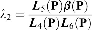
From equation (15), the images
Inference 2
From proposition 2, the simple six-point graph is composed of five arbitrary points and one of the images of the circular points on the circle image satisfies Pascal’s theorem and therefore, one of the images of the circular points can be solved.
It is apparent that an inference is established according to proposition 2 and therefore, the proof process can be omitted.
Computation of the camera intrinsic parameters
The image of the absolute conic is
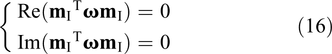
where Re and Im denote the real and imaginary parts, respectively. The image of the absolute conic
Based on proposition 2 and inference 2, we propose the following camera calibration procedure: Step 1: Capture three images from different orientations. Step 2: Extract the feature points using Canny edge detector after segmenting the image by a threshold
23
and fit the feature points to get the conic using the least squares method.
24
Step 3: Solve the appropriate points on the fitted conic according to proposition 2 or inference 2 and compute the images of the circular points according to equation (15). Step 4: Obtain
Experiments
To verify the effectiveness of our proposed calibration method and test its sensitivity to noise, we performed a large number of experiments using simulated data and real images.
Computer simulations
For the computer simulations, the intrinsic parameters used with the camera were fu = 500, fv = 600, u 0 = 400, v 0 = 300, and s = 0.
Effect of positions of points on the intrinsic parameters
By choosing four feature points on the circle image and adding circular points to form a hexagon, the diverse connective sequence of the intersection points of the pairs of opposite sides of the hexagon may have 60 different Pascal lines. With the help of Pascal’s theorem and its inference, the general constraint equations on the conic are transformed into the form of the constraint about Pascal’s line. No point matching is needed between the images, but the relative position of the four points will influence the accuracy of the calibration results. Hence, we investigated the effect of Gaussian noise on the standard deviations of fu , fv , u 0, v 0, and s for different test cases of the relative positions of the four feature points. Because the conic is an ellipse on the image plane, the conic is divided into four parts according to the major axis and minor axis of the ellipse. Five cases were considered for the distributions of the four feature points: average (Figure 3(a)), three-one (Figure 3(b)), half (Figure 3(c)), two-two (Figure 3(d)), and all (Figure 3(e)). Gaussian noise with a mean of zero and variance of σ was added to every pixel in the conic for the five test cases. The variance σ was varied from zero to two pixels. We performed 50 independent simulations for each value of σ and determined the deviations of the camera intrinsic parameters for the five test cases, as shown in Figure 4(a) to (e). The simulations were similar to the situation given in inference 2, and therefore, the tests can be omitted.
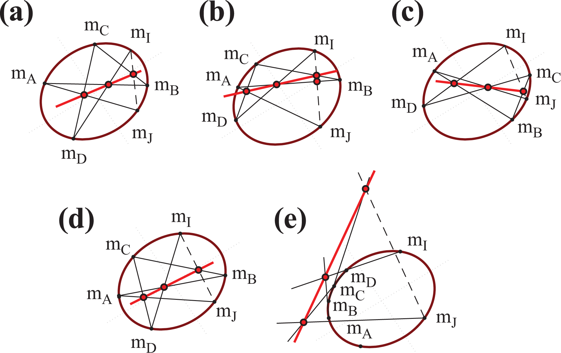
Test cases of the relative positions of the feature points: (a) average, (b) three-one, (c) half, (d) two-two, and (e) all.

Standard deviation curves of (a) fu , (b) fv , (c) u 0, (d) v 0, and (e) sas a function of the Gaussian noise variance σ for the five test cases shown in Figure 3.
The standard deviation curves of the five intrinsic parameters (fu , fv , u 0, v 0, and s) as a function of the Gaussian noise variance σ are shown in Figure 4. It can be observed that the standard deviations of the intrinsic parameters increase in an almost linear fashion with increasing Gaussian noise variance. However, at the same Gaussian noise variance, the standard deviations are the lowest for the “average” case compared to all the test cases considered in this study. For this reason, the “average” case is the most suitable test case for the calibration method.
Comparison with other calibration methods
To assess the effects of Gaussian noise, we compared our calibration method with those developed by Huang et al. 5 and Zhang 11 in recent years, where a circle is used as the calibration template. The camera intrinsic parameters were computed based on proposition 2 (PT1), inference 2 (PT2), and the methods proposed by Huang et al. 5 and Zhang. 11 In our calibration methods (PT1 and PT2), the feature points were chosen based on the following criterion: The distributions of the feature points in the conic must be relatively uniform. Next, Gaussian noise with variance σ was added to each point in the conic. The variance σ was varied from zero to two pixels.
We conducted 50 experiments for each value of σ and then determined the average values of the camera intrinsic parameters. Further, we compared the standard deviation curves of fu , fv , u 0, v 0, and s obtained from our proposed calibration methods with those obtained by the calibration methods of Huang et al. 5 and Zhang, 11 as shown in Figure 5. It can be seen that the standard deviation curves of fu , fv , u 0, v 0, and s increase in an almost linear fashion with increasing Gaussian noise variance σ. However, at the same Gaussian noise variance, the standard deviations of the intrinsic parameters are lower than those obtained using the methods of Huang et al. 5 and Zhang. 11 It is evident that our calibration methods (PT1 and PT2) are more effective within the Gaussian noise variances investigated in this work.

Standard deviation curves of (a) fu , (b) fv , (c) u 0, (d) v 0, and (e) s as a function of the Gaussian noise variance σ for different calibration methods.
Real data experiments
We also performed experiments to validate our proposed calibration method, in which the resolution of the camera was 2456 × 2058 pixels. The calibration template consisted of a disc and checkerboard. A robot manipulator was used to capture images of the calibration template from different orientations (Figure 6(a) to (c)), and three images were selected, as shown in Figure 7(a) to (c). Canny edge detector was used to extract the contour of the circular image in Figure 7(a) to (c); the results are shown in Figure 8(a) to (c). The least squares method was used to fit the equation of the contour. The four points were calculated from the equation fitted of the circular images that satisfy the “average” case for PT1 according to the major axis and minor axis of the conic equation. Thus, the intrinsic parameters of the camera were solved using our proposed calibration methods (PT1 and PT2) as well as those developed by Huang et al. 5 and Zhang. 11 The intrinsic parameters of the camera obtained from the experiments are summarized in Table 1.

(a) to (c) Photographs of the robot manipulator used to capture images of the calibration template (disc and checkerboard) at different orientations.

(a) to (c) Photographs of the calibration template (disc and checkerboard) captured from different orientations.

(a) to (c) Extraction of the contour of the circular image and checkerboard using Canny edge detector.

aThe unit for all camera intrinsic parameters is pixels.
To further verify the validity of the camera intrinsic parameters presented in Table 1, the corners of the checkerboard in Figure 7(a) and (b) were extracted using the Harris algorithm, 25 as shown in Figure 9(a) and (b). The results in Table 1 were used to reconstruct the three-dimensional (3-D) information of the checkerboard in Figure 9 based on the polar geometric constraints 26 of point pairs in the two images. The 3-D reconstruction results are shown in Figure 10(a) to (d). We calculated the angle between any two straight lines in the parallel and perpendicular orientations by fitting the lines of each row and column in Figure 10 using the least squares method and determined the average values to verify the parallelism and orthogonality of the lines, as shown in Table 2. It should be noted that all the angles presented in Table 2 are approximations of the actual values. It is apparent that our proposed calibration methods (PT1 and PT2) are effective within a certain range of error.

(a) and (b) Extraction of the corners of the checkerboard using Harris algorithm.

Average angle between any two straight lines in the parallel and perpendicular orientations in Figure 10.a

aThe unit for the average angles is degrees (°).
Conclusions
In this article, we proposed a calibration method in which the intrinsic parameters of a pinhole camera are determined based on Pascal’s theorem and its inference in order to expand the range of applications for the calibration method. In addition, we extended Pascal’s theorem and its inference to the affine plane in the complex field to obtain the constraints of the images of the circular points. Further, the general constraint equations on the conic are transformed into the form of the constraint about the Pascal’s line. Our calibration method directly uses the properties of a circle and infinite line without the need to consider the geometric position relationships between the circles. Based on the images of the circular points on the conic, we can obtain the nonlinear equations of the images of the circular points. We computed the images of the circular points using the Newton iteration method to determine the intrinsic parameters of the camera. The results of the simulations and experiments performed prove the effectiveness of our proposed camera calibration method.
Footnotes
Declaration of conflicting interests
The author(s) declared no potential conflicts of interest with respect to the research, authorship, and/or publication of this article.
Funding
The author(s) disclosed receipt of the following financial support for the research, authorship and/or publication of this article: This work was supported by the National Natural Science Foundation of China (NSFC) [Grant Nos. 61663048, 11861075], the Program for Innovative Research Team (in Science and Technology) in Universities of Yunnan Province, and the Key Joint Project of the Science and Technology Department of Yunnan Province and Yunnan University [Grant No. 2018FY001 (-014)].