
Abstract
Two linear calibration methods based on space-line projection properties for a paracatadioptric camera are presented. Considering the central catadioptric system, a straight line is projected into a circle on the viewing spherical surface for the first projection. The tangent lines in a group at antipode point pairs with respect to the circle are parallel, with the infinity point being the intersection point; therefore, the infinity line can be obtained from two groups of antipode point pairs. Further, the direction of the polar line of an infinity point with respect to the circle is orthogonal to the direction of its infinity point. Hence, on the imaging plane, images of the circular points or orthogonal vanishing points are used to determine the intrinsic parameters. On the basis of the properties of the antipodal point pairs and a least-squares fitting, a corresponding optimization algorithm for line image fitting is proposed. Experimental results demonstrate the robustness of the two calibration methods, that is, for images of the circular points and orthogonal vanishing points.
Keywords
Introduction
The rapid development of computer vision technology has caused an increase in the stringency of visual performance requirements. 1 In general, increasing the field of view improves the visual performance of a camera. 2,3 An effective means of enhancing the field of view of a camera is to incorporate mirrors into the camera, as proposed by Hecht and Zajac. 4 The resulting configuration system is called a catadioptric system. Such a system can be classified into two types on the basis of the presence or absence of a unique effective viewpoint, that is, a central or noncentral system, respectively. 5 The surface of the mirror of a central catadioptric system is categorized into four types: parabolic, hyperbolic, ellipsoidal, and planar mirrors. The basic feature points in an image captured by a central catadioptric camera can easily be converted into three-dimensional (3-D) coordinates by a projection inverse—a technique broadly applied in vision systems. 4 –6
Geyer and Daniilidis 6 proposed a unified model of projection image formation for a central catadioptric system that is equivalent to two-step projection by a unit sphere. The calibration methods for central catadioptric cameras can be classified into four categories: self-, 7,8 point-, 9 –11 line-, 12 –19 and sphere-based calibration. 20 –23 This article considers methods that exploit the projection properties of one line in the unit sphere model to calibrate a paracatadioptric (i.e. with a parabolic mirror) camera.
Many calibration methods that employ 3-D space lines exist for central catadioptric cameras. The advantage of using lines for calibration is that the target scene usually contains lines; thus, a specific template is not required. Geyer and Daniilidis 12 calibrated a paracatadioptric camera using an image of two groups of parallel lines and an image of three lines. They also proposed unifying projection model theory for central catadioptric systems with a unique effective viewpoint. 13 In their model, the projective lines and points are dual to each other. They also posited a geometric argument in which the center catadioptric system except the planar projection can be calibrated by one image of lines. Further, Barreto and Araujo 14 studied the line images and presented several projective invariant properties of the central catadioptric system using one image of three or more lines to calibrate the camera. The properties include the fact that the intersections of the images of the lines are the principal point, and the polar lines of the principal point with respect to the line images intersect the line image at the image of the circular points. According to the cross ratio invariants of the line image, the mirror parameter is determined. In addition, Wu et al. 15 derived the linear constraints of the line image according to the relationship between the projection of the antipodal points, the projection properties of the lines in the central catadioptric camera, and the cross ratio invariants. Any central catadioptric camera can be calibrated by linear constraints using one image of three or more lines. Ying and Hu 16 proposed a calibration method that uses the geometric invariants of an image of the line and sphere in central catadioptric cameras. One-line image provides three invariants and a sphere provides two invariants. The images of two lines or three spheres can calibrate central catadioptric cameras. Further, Ying and Zha 17 reported that all line images in a central catadioptric system with the same intrinsic parameters belong to the family of conics with two degrees of freedom. They detected line images via the Hough transform and calibrated the camera according to the relationship between the camera intrinsic parameters and the family of conics. Vandeportaele et al. 18 used one image of three or more lines to calibrate paracatadioptric cameras by applying the geometric distance obtained from the intrinsic parameters instead of the algebraic distance. The approach demonstrates that a line is projected to a straight line or circular arc. Finally, Wu et al. 19 proposed a calibration method for paracatadioptric cameras based on lines that are not a conic fitting under a single view. The method establishes sets of linear equations for the camera intrinsic parameters, focal lengths, and skew factor, and the principal point is the image center of the mirror contour.
On the basis of the abovementioned literature analysis, this article presents methods of paracatadioptric camera calibration utilizing the projection of one line and the properties of the polar line of an infinity point with respect to a circle. Considering the unit sphere model, a straight line is projected to a circle of the spherical surface. For a point taken on the circle, the two tangents passing through an antipode point pair are parallel and intersect at the infinity point. Further, the direction of the polar line of an infinity point with respect to the circle is orthogonal to the direction of the infinity point. Therefore, on the image plane, images of the circular points and orthogonal vanishing points can be obtained to determine the camera intrinsic parameters. Then, on the basis of the properties of the antipodal point pairs and a least-squares fitting, an optimization algorithm for line image fitting can be implemented. In this work, two such calibration algorithms are proposed.
The remainder of this article is organized as follows. A review of the unit sphere model for central catadioptric cameras and several related concepts are presented in the next section. Then, two calibration algorithms for paracatadioptric cameras from one line image are described in detail, and an algorithm for line image fitting is presented. The two calibration algorithms are next verified by simulation tests and real experiments. Finally, some concluding remarks are presented.
Preliminaries
In this section, we briefly review the projection process of a central catadioptric system with the unity sphere model, 6 the relationship of the antipodal image points, 15 and the properties of the polar line of the infinity point with respect to a circle. 24
Central catadioptric projection system
As shown in Figure 1, the projection of a 3-D scene point in the central catadioptric camera is equivalent to two-step projection by a unit sphere.
6
First, in the world coordinate system

Projection model of the 3-D point
Let the pinhole-camera intrinsic parameter matrix be

where fu
and fv
are the focal lengths for the u- and v-axis directions, respectively,

where λ
1 and λ
2 are two nonzero scale factors,
Similarly, the projection of a 3-D scene line in the central catadioptric camera is equivalent to two-step projection by a unit sphere model. First, a 3-D space line
Proposition 1
In Figure 1, if
where

Properties of the polar line of infinity point with respect to a circle
Definition
Given a point
Proposition 2
The direction of the polar line of an infinity point with respect to a circle and the direction of the infinity point are orthogonal.
Proof
As shown in Figure 2, the polar line of the infinity point

Properties of the polar line of infinity point with respect to a circle.
Paracatadioptric camera calibration and line image fitting
In this section, through an analysis of the projection properties of one line for a paracatadioptric camera, the manner in which the properties of the polar line of the infinity point with respect to a circle can be used for the calibration of a paracatadioptric camera is explained, which corresponds to proposition 3 (for orthogonal vanishing points) and proposition 4 (for imaged circular points) in the following. According to the properties of the antipodal points and a least-squares fitting, an optimization algorithm for line image fitting is proposed.
Properties of the line image for a paracatadioptric camera
Proposition 3
For a central catadioptric system, given two different points on the line image, we can obtain two groups of orthogonal vanishing points.
Proof
As shown in Figure 1, for the unit sphere model, the projection of the line
As shown in Figure 3, on the catadioptric image plane, the line image is denoted by

where × is the vector product and ⋅ is the product. We denote the images of


Polar line of a vanishing point with respect to a line image.
The vanishing line

The polar lines of


On the basis of proposition 2,
The choice of the locations of the images points
Proposition 4
For a central catadioptric system, given two different points on the line image, the images of the circular points can be obtained.
Proof
For proposition 3, the vanishing line
Line image fitting in a central catadioptric system
The image of a straight line is conic in a central catadioptric system, but only a section of the conic is visible in the image plane. Therefore, the line image fitting is inaccurate when only a section of the conic is known.
Proposition 5
In a central catadioptric system (see Figure 1), with knowledge of the image point
Proof
Let the conic

We minimize the algebraic distance

where (xj
, yj
) are the coordinates of

where

We then minimize the objective function; that is, we obtain the partial derivative of equation (13) with respect to

The solution of equation (14) is

and the coefficients of the conic are
Similarly, through normalization with b = 1, c = 1, d = 1, e = 1, and f = 1, the coefficients of a conic, that is,

Line-based calibration method for a paracatadioptric camera
A group of orthogonal vanishing points

A group of circular points

The points

where Re and Im represent the real and imaginary parts, respectively.
Note that a group of orthogonal vanishing points provides one linear constraint on the IAC, but all of the orthogonal vanishing points for a plane only provide two constraints on the IAC. 24 A group of the images of the circular points can provide two constraints on the IAC. Therefore, at least three views of one line should be provided to satisfy propositions 3 and 4.
The two algorithms proposed in this study, that is, for the images of the circular points (proposition 4) or orthogonal vanishing points (proposition 3), consist of the following steps:
Step 1: Views including at least one line image are input, and the pixel coordinates of the line image and the projective contour of the mirror are extracted in
Step 2: Two different points,
Step 3: The vanishing line
Step 4: The two common intersection points (i.e. the imaged circular points) for the vanishing line
Step 5: (a) When the orthogonal vanishing points are known, solve for
(b) When the images of the circular points are known, solve for
Step 6: Determine
Experiments
We tested the validity and robustness of two calibration algorithms via simulation tests and real experiments. Further, we compared the results with Barreto and Araujo’s 14 three-line method and Wu et al.’s 15 calibration methods. In the following, the methods derived from propositions 3 and 4 are referred to as “Ours 1” and “Ours 2,” respectively.
Experiment using simulation data
Let the simulated central catadioptric camera be a paracatadioptric camera, that is, ξ = 1, with the five intrinsic parameters being
Simulated line images.
In the simulation experiment, a line image was fit according to the method presented in proposition 5 (step 1 of both algorithms). Five hundred points were chosen on each line image, with 200 points chosen on the mirror projective contour. To test the sensitivity of the calibration methods to noise, Gaussian noise with a zero mean and a standard deviation σ of zero to three pixels was added to the chosen pixel coordinates. After the noise was added, we compared the difference in the results given by our proposed methods (corresponding to propositions 3 and 4) and those reported in the literature. 14,15 For each noise level, 1000 independent trials were performed to determine the absolute error of the intrinsic parameters. The average results of the absolute error are shown in Figure 5(a) to (e). The results indicate that, when σ is zero, the absolute errors of the intrinsic parameters are zero; the absolute errors of our two methods and the methods of Barreto and Araujo 14 and Wu et al. 15 increase virtually linearly with the noise level σ. However, the absolute errors of our proposed algorithms increase more slowly than those of the other calibration algorithms. The contrast in the simulation experimental results confirms that our proposed methods are feasible.

Variations in the absolute errors of the intrinsic parameters with different calibration methods under varying levels of Gaussian noise.
We compared the runtimes of the four methods using MATLAB 2016a implementations of all algorithms on a computer equipped with a Pentium IV processor running at 2.1 GHz and 2.0 GB of RAM. We performed 1000 independent trials to obtain the average values of the runtimes, the results of which are listed in Table 1. The average value of the runtimes of Wu et al. 15 is far greater than the other methods because the generalized inverses of antipodal image points needed to be computed before establishing the linear constraints between the antipodal image points and the IAC.
Runtimes for the four algorithms (unit: seconds).

Experiment with real data
In the real experiment, a checkerboard was used to calibrate the model to replace the lines. A catadioptric camera shot the scene from different viewing angles, and three pictures were selected as real images. Three experimental images with resolutions of 3680 × 3488 pixels are shown in Figure 6(a) to (c). First, the edges were detected using the Canny algorithm to detect the edges of the images, as shown in Figure 7(a) to (c). The equations of the line images were obtained using the method given in proposition 5 (step 1 of both proposed algorithms). Then, the intrinsic camera parameters were obtained on the basis of our calibration algorithms and the methods of Barreto and Araujo 14 and Wu et al. 15 The calibration results are listed in Table 2 for the real experiments. Note that the calibration results exhibit little difference; thus, our calibration methods are efficient. To further check the accuracy of the calibration results in Table 2, Figure 6(a) is taken as an example and rectified to its projective image using the determined intrinsic parameters, as shown in Figure 8(a) to (d). Again, the results indicate that our proposed calibration algorithms are effective.

Three checkerboard images captured by a paracatadioptric camera.
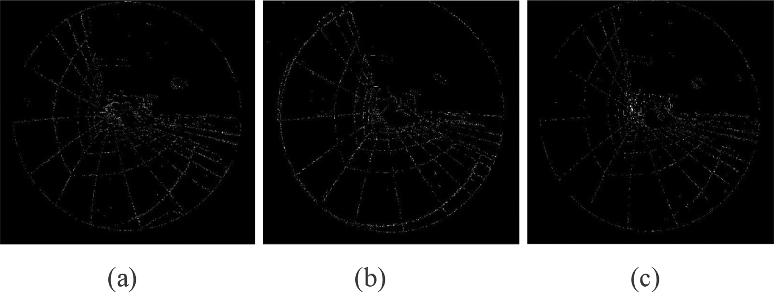
Resulting edges of the three images extracted in Figure 6.
Comparison of the calibration results of the intrinsic parameters with different methods (unit: pixels).


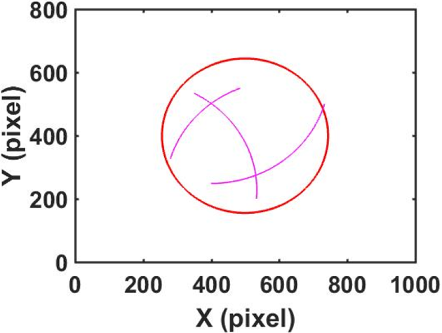
In order to validate the accuracy of the calibration results in Table 2, the checkerboard pattern in Figure 6 was reconstructed. A valid region of the checkerboard pattern images from Figure 6(a) to (c) was chosen. On the basis of the Harris corner detector, 27 the feature points of the checkerboard shown in Figure 9(a) to (c) were selected. Applying the epipolar geometry constraint algorithms for two views of the paracatadioptric camera, 28 52 corresponding points were selected from the two visible sides of the checkerboard image and were then used for reconstruction (see Appendix 1). The reconstruction results obtained on the basis of the data listed in Table 2 are shown in Figure 10(a) to (d). From Figure 10, it is clear that the reconstructed 3-D points are coplanar for the two sides.
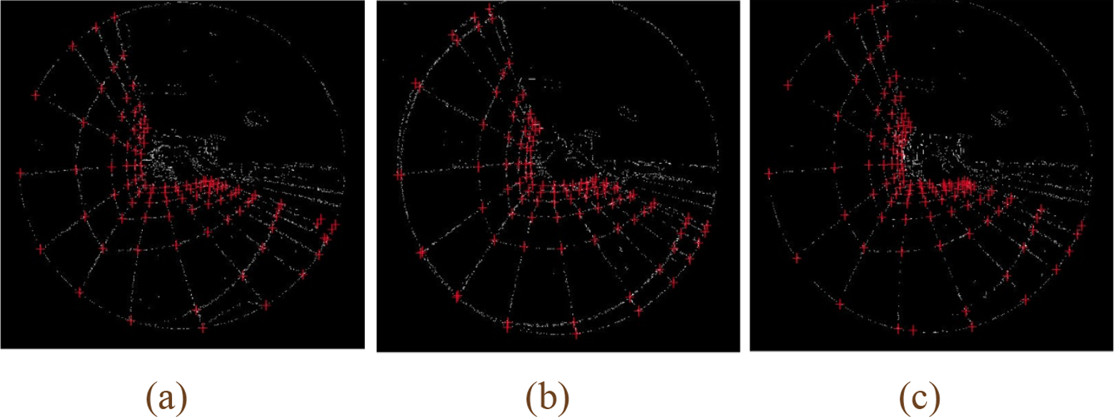
(a) to (c) Results of Harris corner detection for Figure 7(a) to (c), respectively.

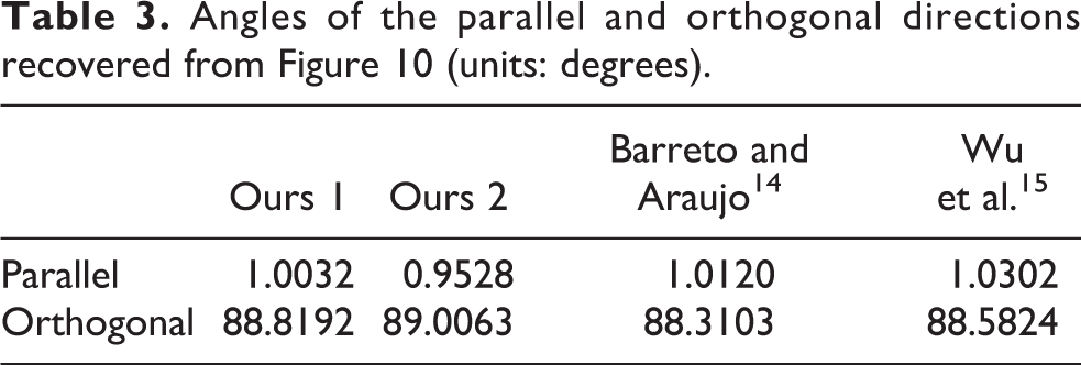
The parallelism and orthogonality in Figure 10(a) to (d) were also checked. First, according to least-squares fittings, the equations of the lines for every row or column in Figure 10(a) to (d) were obtained. Then, the average of the angles between any two points in parallel directions was calculated. Similarly, the average of the angle for the orthogonal direction was calculated. The results for the angles obtained from Figure 10 are summarized in Table 3. The real angle for the parallel line direction is 0°, and that for the orthogonal direction is 90° on the calibration checkerboard pattern. The 3-D reconstruction angles are similar to the true values in the parallel or orthogonal direction. This indirectly proves that the calibration results of the intrinsic parameters in Table 2 are effective.
Angles of the parallel and orthogonal directions recovered from Figure 10 (units: degrees).
Conclusion
A camera calibration algorithm is often related to a vanishing point or an image of circular points. In this work, for application to three images containing one line, two calibration methods based on the properties of the polar line of an infinity point with respect to a circle in a paracatadioptric camera and incorporating the orthogonal vanishing points or the images of the circular points were proposed. In this approach, for the unit sphere model, a straight line is projected to a circle on the unit sphere. The tangents of the circle at antipodal point pairs are parallel and intersect at an infinity point. Then, an infinity line can be obtained according to two groups of antipodal points. The direction of the polar line of an infinity point with respect to a circle and the direction of the infinity point are orthogonal. Further, the intersection point of the infinity line and the circle is a circular point. According to the projective invariance, the images of the circular points and the orthogonal vanishing points can be determined. The camera intrinsic parameters can then be obtained according to the relationship between the images of the circular points or orthogonal vanishing points and the intrinsic parameters. The experimental results verify the robustness of our proposed calibration methods. An optimization method based on the fitting of one line image according to the relationship between antipodal points was also proposed.
In the literature, 14 on the basis of the geometric invariance under a projective transformation, one image containing three or more lines is used to calibrate the camera. A pair of lines is projected into two circles and intersect at a pair of antipodal points on the viewing spherical surface. Three lines are projected into three circles, which intersect at three pairs of antipodal points, and the intersection point of the three lines passing though the antipodal points is the center of the three circles. The polar line of the center of the circle with respect to the circle is the infinity line, which intersects the circle at the circular points. On the basis of the geometric invariance under a projective transformation, the three lines passing through the intersection points corresponding to the line images intersect at the principle point, that is, the image of the center of the circle. The polar lines of the principal point with respect to the line image intersect the line image at the image of the circular points. The images of the circular points are used to determine the intrinsic parameters. In the literature, 15 a relationship between the projection on the viewing sphere of a space point and its image was derived to obtain a linear constraint between the antipodal image points and the IAC. First, the principal point was determined by the intersecting point of the three line images. Then, two pairs of antipodal image points were taken from each of the three line images according to the constraint, and central catadioptric cameras were calibrated for a single view.
In this study, the elements at infinity are obtained on the basis of both the properties of the tangent lines of a circle and the properties of the polar line of an infinity point with respect to a circle.
Footnotes
Declaration of conflicting interests
The author(s) declared no potential conflicts of interest with respect to the research, authorship, and/or publication of this article.
Funding
The author(s) disclosed receipt of the following financial support for the research, authorship, and/or publication of this article: This work was supported by the National Natural Science Foundation of China (NSFC) (61663048 and 11361074).