
Abstract
Combined vision system is a perspective display concept to enhance a situation awareness of the pilots during aircraft landing, which integrates a real 2-D image captured from forward-looking infrared camera with a synthetic 3-D image derived by the aircraft pose and terrain database. However, the inertial measured errors significantly affect the conformal display of combined vision. This article proposes a novel method for real and synthetic images registration based on visual–inertial fusion. It includes the following key steps: (1) detect and extract the real runway features from forward-looking infrared image; (2) generate the synthetic runway features simultaneously; (3) set up vision measurement model with real and synthetic runway features; (4) integrate inertial data and visual observations in the square-root unscented Kalman filter; (5) create a synthetic 3-D scene by the filtered pose data and integrate it with a real 2-D image. The experimental results demonstrate that our method can guarantee the conformal display of combined vision system in GPS-denied and low visibility conditions.
Keywords
Introduction
The landing is the most accident-prone flight stage for the fixed-wing aircrafts since it needs the aircraft to rapidly descend and brake in a narrow airspace. The flight accidents in landing phase account for more than 70% of the total flight period accidents worldwide, of which 30% of all fatal accidents are categorized as controlled flight into terrain (CFIT) due to the lack of outside visual reference and situation awareness. 1 Recently with the rapid development of image processing and infrared sensing, they have been applied to airborne cockpit electronic system to improve flight safety especially in GPS-denied and low visibility conditions. As a novel airborne assistant landing means, combined vision system (CVS) can provide an equivalent visual operation ability for the crew with a perspective flight scene 2 during landing. It integrates the real 2-D image captured by forward-looking infrared (FLIR) camera and the synthetic 3-D image derived from the aircraft pose and the terrain database, 3 then the superimposed image is displayed on a primary flight display to enhance flight visibility of the crew. It is remarkable that the real 2-D image must be conformal to the synthetic 3-D terrain in the combined vision in real time. Otherwise, it will mislead the crew to cause flight accident. However, it is difficult to directly align the FLIR image with the synthetic terrain due to some inevitable errors.
The real 2-D image and the synthetic 3-D image can be understood as two independent perspective images relative to the same physical scene, and they are photographed at the same time by the same camera under the measured pose and the real pose. When the measured pose is not equal to the real pose, the deviations between them lead to obvious misalignments between the real image and the synthetic image. The main reasons for the deviations include the sensors installation errors, image processing delay, terrain data errors, and inertial navigation system (INS) measurement errors. 4 The deviations can be partially eliminated by relative pose calibration, 5 –7 time synchronization, 8 –10 and high precision terrain database. However, the measured pose errors derived from the random drifts of accelerometers and gyroscopes are the critical issues to be solved.
In recent years, researchers in Honeywell adopted the integrated navigation of laser INS and local area augmentation system to support alignment of real and synthetic images. 11 Horn in German Aerospace Center (DLR) used fuzzy logic-based method. 12 The researchers in Russia State Research Institute of Aviation Systems (GosNIIAS) proposed a morphological registration method, 13,14 while the researchers in India National Aerospace Laboratory (CSIR-NAL) used differential GPS (DGPS) instruments to provide accurate navigation and positioning for ESVS system. 15 However, these traditional methods rely heavily on high-precision INS and ground-based augmentation system (GBAS), they can neither be used to low-cost general aviation nor robustly run in GPS-denied condition. Besides, visual cues implied in FLIR images are not fully excavated and utilized. Consequently, how to satisfy the accurate registration of real and synthetic images in CVS with low cost and high robustness has become an important topic.
An alternative solution to achieve aircraft landing pose is vision-aided navigation, which is characterized by low cost, autonomy, and high precision. In recent years, many vision-based motion estimation methods for the fixed-wing aircraft landing have been proposed, which can be divided into two categories, the ground-based methods 16 –19 and the airborne-based methods. 20 –24 The former often utilizes cameras located on the ground to detect, track, and position the aircraft, which has high positioning accuracy. However, these methods cannot estimate the attitude of the aircraft. The latter fully utilizes the airborne sensors and on-board visual navigation algorithms to achieve autonomous navigation. Gui et al. 20 proposed an accuracy vision navigation method for UAV landing based on artificial markers. Nevertheless, this method needs to place four infrared lamps on the runway in advance. Cai et al. 21 adopted square root unsent Kalman filter (SR-UKF) to fuse homography matrix and inertial measurements to implement the UAV auto landing navigation. However, it is very difficult to satisfy the precondition of this method that the world coordinates of the point array are known. Fan et al. 22 employed spectral residual saliency map to detect region of interest (ROI), then select sparse coding and spatial pyramid matching to recognize runway and use orthogonal iteration to estimate position and attitude. Due to the low accuracy of runway detection, this method cannot achieve precise motion estimation of the aircraft. Ruchanurucks et al. 23 used Efficient Perspective-n-Point solution to estimate relative pose for an automatic landing-aided system for landing a fixed-wing UAV on the runway. Nevertheless, the accuracy of this method is more susceptible to the errors of image detection. Patruno et al. 24 proposed a landing approach based on human-made land marker for multi-rotor unmanned aerial vehicle. It is not suitable for approach and landing navigation of fixed-wing aircraft. Gibert et al. in Airbus 25 designed two nonlinear observers based on high gain approach and sliding mode theory and apply them to a vision-based landing solution for civil aircraft in an unknown runway. However, the update rate of aircraft states is too low to satisfy system requirements. As the basis of visual landing navigation, the results of runway detection can affect the accuracy of pose estimation directly. Wu et al. 26 adopted a fast line segment detector (LSD) 27 to detect the line segments and used regional self-similarity and contextual information to recognize the runway. However, it can be distracted by the edges of rivers, roads, and taxiways easily. Liu et al. 28,29 designed and improved a method based on multi-sensor fusion to realize real-time runway detection. Although it runs very fast, it cannot accurately extract runway features. Moore et al. 30 utilized an image matching pipeline to determine runway by comparing with many stored runway images. Although the above methods have achieved remarkable progress in vision landing navigation, they cannot provide accurate aircraft pose parameters with high update rate to support registration of 2-D–3-D images in low visibility condition.
For the purpose of implementing the accurate registration between real 2-D image and synthetic 3-D image in CVS, a novel method based on visual–inertial fusion framework is proposed in this article. Firstly, an existing runway detection method 31 is improved to accurately detect and extract three vertexes (the front left corner, the front right corner, and the vanish point of the runway) of runway triangle contour from FLIR images instead of general four corners or four edges. Simultaneously, synthetic runway features are derived by runway geo-information and aircraft’s pose parameters. Secondly, we propose to use real and synthetic runway features to create vision cues and integrate them with inertial data in SR-UKF 32 to estimate motion errors. Meanwhile, the measured motion states are corrected with the estimated state errors. Thirdly, the synthetic 3-D scene is generated by the corrected pose data and integrated with real 2-D FLIR image. Meanwhile, the airworthiness requirement of the CVS image conformality 2 is transformed into the pixel deviation between real and synthetic images in row and column directions to be convenient for verification. Finally, we design a flight data acquisition platform equipped on a general aircraft. The proposed method is proven to be able to guarantee the conformal display by real flight data.
The article is organized as follows: the second section analyzes the landing phase by CVS, defines reference frames, and proposes the algorithm framework. The third section presents the visual–inertial fusion method in detail. The experimental results are shown in the fourth section. Finally, the conclusion and future work are drawn in the fifth section.
System overview
Landing by CVS
During the landing, pilots follow the instrument flight rules before manipulating the aircraft to a decision height (DH = 60.96 m). If visual landing conditions are met at DH, the aircraft will continue to land, otherwise it will be pulled up at once. The pilot follows the visual flight rules from DH to the ground. With the help of CVS, the pilot can decide to land or pull up before descending to 30.48 m in low visibility conditions, which can extend the decision time and increase the landing probability. As shown in Figure 1, during the period of aircraft descending from 152.4 to 30.48 m, CVS not only provides the perfect registration of real and synthetic images but also achieves the accurate pose estimation of the aircraft.

Approach and landing by CVS. CVS: combined vision system.
Reference frames
In the proposed method, an FLIR camera and an INS are installed on the aircraft. As shown in Figure 2, these reference frames obey to the right-hand rule in this article.

Reference frames and runway model. INS: inertial navigation system.
{D} represents the geodetic reference frame, any point i in {D} is
Algorithm framework
The foundation of the proposed image matching approach is the SR-UKF that integrates inertial data with accurate vision observations and runway geographic information. All input images are captured and synchronized with the inertial data by unified time stamp. In the SR-UKF, the processing model is the error propagation equations of INS, while the vision measurement model comes from real and synthetic runway features. Thus, the 3-D synthetic scene is derived by the filtered pose parameters and airport terrain database, and it can be strictly aligned with the real image. As shown in Figure 3, the part in red box is the core of this algorithm framework.

Algorithm framework for conformal display in CVS. CVS: combined vision system; INS: inertial navigation system; SR-UKF: square-root unscented Kalman filter.
Real and synthetic images registration
Process model
Firstly, the system state is defined as follows

where

where
Considering the discrete-time, the model can be written as follows

where

Measurement model
Synthetic runway features
One point 1. From {D} to {E}
The geodetic coordinate can be transformed into the ECEF coordinate, as follows

where
2. From {E} to {G}
Any known point

where
3. From {N} to {B}
The navigation coordinate system {N} has the same origin with the body coordinate system {B}, the former rotates yaw-pitch-roll angle round X N-Y N-Z N axis to the latter in sequence, as follows

where
4. From {B} to {C}
The rigid connection between aircraft body and camera contains a relative rotation

5. From {C} to {P}
According to the pinhole camera model, 33 the pixel coordinate projection of any point in the pixel coordinate system is
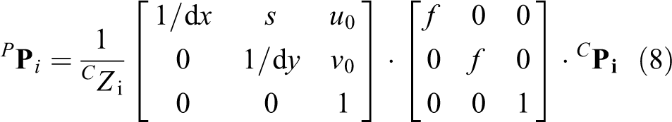
where

where ψ, θ, and ϕ denote yaw, pitch, and roll of the aircraft, and La,

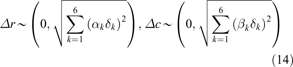
To further analyze the error distribution of the projected pixel, the error transfer equations of the row pixel and the column pixel can be obtained from equation (9)

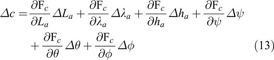
where
where

Probability distribution of point A.
Real runway features
This article improves an existing hierarchical method 31 from coarse to fine to accurately detect and extract runway features from the FLIR image. In the coarse layer, You Only Look Once (YOLO) algorithm 34,35 is trained to detect the ROI of the runway. Due to its special geometry, line segments give a high-level description of airport runway. In the fine layer, the line segments are extracted from ROI by EDlines detector 36 and are classified into the corresponding line set characterized by its neighborhood and slope. Some random points are selected from these line segments by its weight. Then, these random points in each line set are fitted into a complete runway line by RANSAC. Finally, three vertexes of the runway triangle contour can be calculated by the right edge, the left edge, and the front edge of the runway.
1. ROI detection
In this article, the YOLO algorithm 34,35 is used to detect ROI of the airport runway, which is a target detection system based on a single neural network. The detection process is to (1) divide an input image into 7 × 7 networks, (2) give each network a prediction of two borders, to (3) remove the less possible window according to the 7 × 7 × 2 target windows predicted in the last step and use the non-maximum suppression to remove the redundant windows.
2. Line segments extraction
Line segments based on its special geometry can give a high-level description of airport runway. An ideal line segment detection algorithm can process any images regardless of its origin, orientation, or size and extract accurate line segments in real time without parameters tuning. Among existing algorithms, EDLines detector 36 and LSD 27 can satisfy the above-mentioned requirements. However, EDLines runs up to 11 times faster than LSD, 27 which makes it more suitable for real-time runway detection.
3. Runway line fitting
Due to low illumination, weak contrast, and blur in FLIR image, there are three major problems when the line segments’ detectors (e.g. Hough, LSD, and EDLines) are applied to FLIR images: (1) the detected runway edges are composed of small line segments with different orientations; (2) there are often gap-filling segments which lead to discontinuity of runway edges 37 ; (3) when the aircraft is still far from the runway, the projection region of runway onto the image plane is relatively small. It is very difficult to accurately detect and extract the back edge of the runway from the FLIR image. This article uses only three vertexes of the runway triangle as visual cues and proposes a fast method to classify and fit three sets of line segments into three runway edges, as shown in Figure 5.

Runway line segments fitting.
Some symbols are defined to depict these line segments quantitatively, as follows
If a line segment Li falls into the neighborhood of the ideal runway line
4. Vertexes calculation
The right edge, the left edge, and the front edge of the runway intersect each other, so three intersection points are the vertices of the runway triangle, which are
Vision measurement
When

where
Vision–inertial fusion
The UKF adopts a deterministic sampling technique to estimate the state and covariance of the nonlinear models directly. Compared with the EKF, the UKF can predict the state of the nonlinear system more accurately rather than calculate the Jacobian and Hessian matrices of the process and measurement models. Since the UKF need to calculate the square root of state covariance matrix during sigma points at each time update, it may cause negative definite state covariance matrix. However, the SR-UKF requires less numerical computations and has more accuracy using a Cholesky factorization of the error covariance matrix in propagation directly.
32
The visual–inertial fusion based on SR-UKF is presented as follows 1. Initialization


Calculate the matrix square root of the initial state covariance

2. Time update
Sigma points calculation

One-step state prediction


Square root of one-step state prediction
Vision measurement prediction
3. Vision measurement update


State noise prediction:
In the proposed method, the scalar weights are defined as:
Images registration
Considering the flight safety, CVS must provide a conformal display between real and synthetic images, otherwise the mismatched image can mislead or confuse the pilot. The accuracy of the CVS image should not result in a greater than 5 mrad display error at the center of the display at a range of 609.6 m (30.48 m altitude on a 3° glideslope). 2 Therefore, this ergonomics requirement should be changed to the pixel deviation of key elements between real and synthetic images in the horizontal and vertical directions, respectively.
Assuming that the distance from the design eye position to the screen center of the head down display screen is d, the pixel sizes of the head down display (HDD) screen in the horizontal and vertical direction are sh and sv, respectively, then the horizontal pixel deviation of image alignment should not exceed
Experiments
Vehicle and sensor setup
The flight data acquisition platform is Y-12F general aircraft which is equipped with a vision sensors suite (including a FLIR camera), an INS (Applanix AV510), a flight data recorder (FDR, AMPEX miniR 700), an air data computer (ADC, CAIC XSC-6E), and a radio altimeter (RALT, Honeywell KRA405b). The DGPS base station (Trimble R5) is used to provide the ground truth by inertial-DGPS integration. The FDR is charge of recording the real-time measurements of INS, GPS, ADC, and RALT. The complete structure of the flight data acquisition system is shown in Figure 6.

The structure of the flight data acquisition system. FLIR: forward-looking infrared.
The vision sensors suite is mounted on the front of the aircraft radome, which consists of a short-wave infrared (SWIR) camera (NIP PHK03M100CSW0, NIP Co., Ltd., PAMINA), a visible light camera, a mounting bracket, and a metal shell, as shown in Figure 7. This article only discusses FLIR images. Furthermore, the INS and FDR are installed on the cabin deck of the aircraft. The flight data have been collected at a general aviation airport (Pu Cheng, China), and the terrain data of the airport and its surrounding have been surveyed. There are five data sets of takeoffs and landings including fog, haze, cloudy, and sunny weather conditions. Each data set consists of FLIR video (frame rate 24 Hz, resolution 640 × 512), INS date (update 100 Hz), GPS data (update 20 Hz), ADC data (update 16 Hz), and radar altimeter (update 16 Hz), which are labeled with time stamp to synchronize measurements. Moreover, the relative position

Vision sensors installation and aircraft landing.
Besides runway detection needs to train YOLO neural network on workstation, other experiments are implemented on Jetson TX2 board. As shown in Figure 8, the experiment platform is a NVIDIA Jetson TX2-embedded computer board with 6 ARM CPU cores, 256 Pascal GPU cores, and 8 GB memory. Furthermore, a complete landing process under fog condition is used for verifying the proposed algorithm. The aircraft descended from 152.4 m to 14.32 m, through three typical altitudes of 60.96 m, 30.48 m, and 18.29 m, flying for 59.45 s.

The structure of CVS platform prototype. CVS: combined vision system.
Runway detection
Runway detection algorithm includes two parts: runway recognition and feature extraction. In the first part, tiny YOLO is used to recognize the runway target from FLIR video. YOLO needs to be trained on the workstation with Intel Core i7-6700, 3.40 GHz CPU, 8 GB RAM, NVIDIA display card 1070, and OS Ubuntu14.04. In this article, 1000 photos are selected from the FLIR video, in which 800 photos are used as training sets and 200 photos as test sets. This training process iterates 80,200 times and runs 36 h. Therefore, the trained YOLO runs on the embedded computer board TX2, reads FLIR video, and recognizes runway ROI. In the second part, EDLines detector is used to extract line segments from ROI, then these line segments are fitted into runway edges.
As shown in Figure 9, the three row images from up to down are captured at 60.96 m, 30.48 m, and 18.29 m, respectively. In the left column, the red rectangles denote the estimated ROI of runway images. In the middle column, the blued trapezoids represent the synthetic runway edges, which are used to estimate each neighborhood of runway edges. Moreover, some short line segments (red color) are extracted from ROI by EDLines detector. In the right column, the green lines show the three edges of runway.

Runway detection.
The statistics of runway detection listed in Table 1 show that the pixels ratio of ROI/CCD is less than 25%. Obviously, the proposed method is more efficient than others, 38 because of narrowing the detection area.
Experimental result of the runway features under different scenarios.

ROI: region of interest.
Motion estimation
Among motion parameters, the pitch and altitude of aircraft have great influence on the 2-D–3-D image registration of CVS. 39 Therefore, eliminating the random errors of these parameters can effectively guarantee conformal display. In our experiments, the result of INS/DGPS integration is selected as ground truth, and the proposed algorithm is compared with pure INS mode, INS/GPS mode, 40 and INS/GPS/ADC/RALT mode. 41 As shown in Figure 10, the pose error of pure INS is larger than the others, while the estimated pose error of our method is smaller than those of the others. Especially the pitch and altitude of the proposed algorithm are closest to the ground truth.
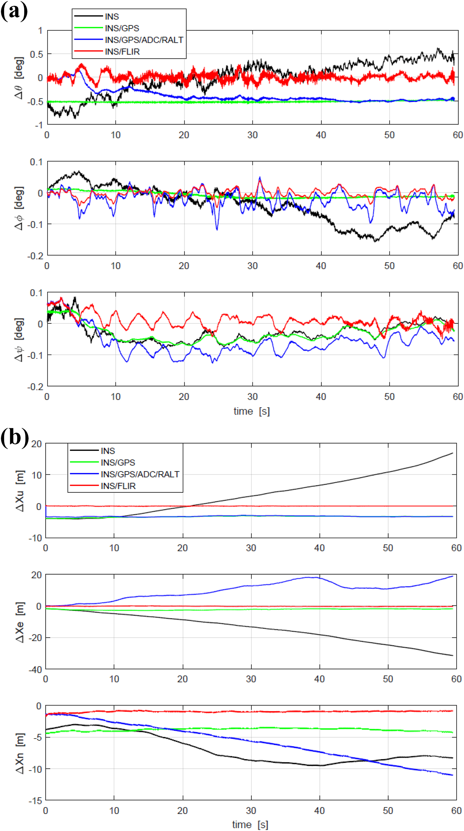
Pose errors estimation. (a) Euler angles and (b) position.
The root mean squared errors (RMSEs) of INS motion parameters are listed in Table 2. This statistic shows that the proposed method is superior to other methods.
The RMS errors of motion estimation.

INS: inertial navigation system; ADC: air data computer; RALT: radio altimeter; FLIR: forward-looking infrared; RMS: root mean square.
Images registration
To verify this proposed algorithm, the synthetic runway features derived by the filtered pose parameters is compared with the real runway features extracted from FLIR image, then the registration validation is judged by the pixel deviation discussed in the section “Images registration.” The triangle area formed by point A, point D, and point V is in the center of the combined vision, and it includes the key elements of a runway. Therefore, the pixel deviations of these three points can fully reflect the registration accuracy of real and synthetic images. As shown in Figure 11, the row and column pixel errors of the front left corner A, the front right corner point D, and the vanish point V are no greater than 7 pixels, which meets the requirement of real and synthetic image registration.
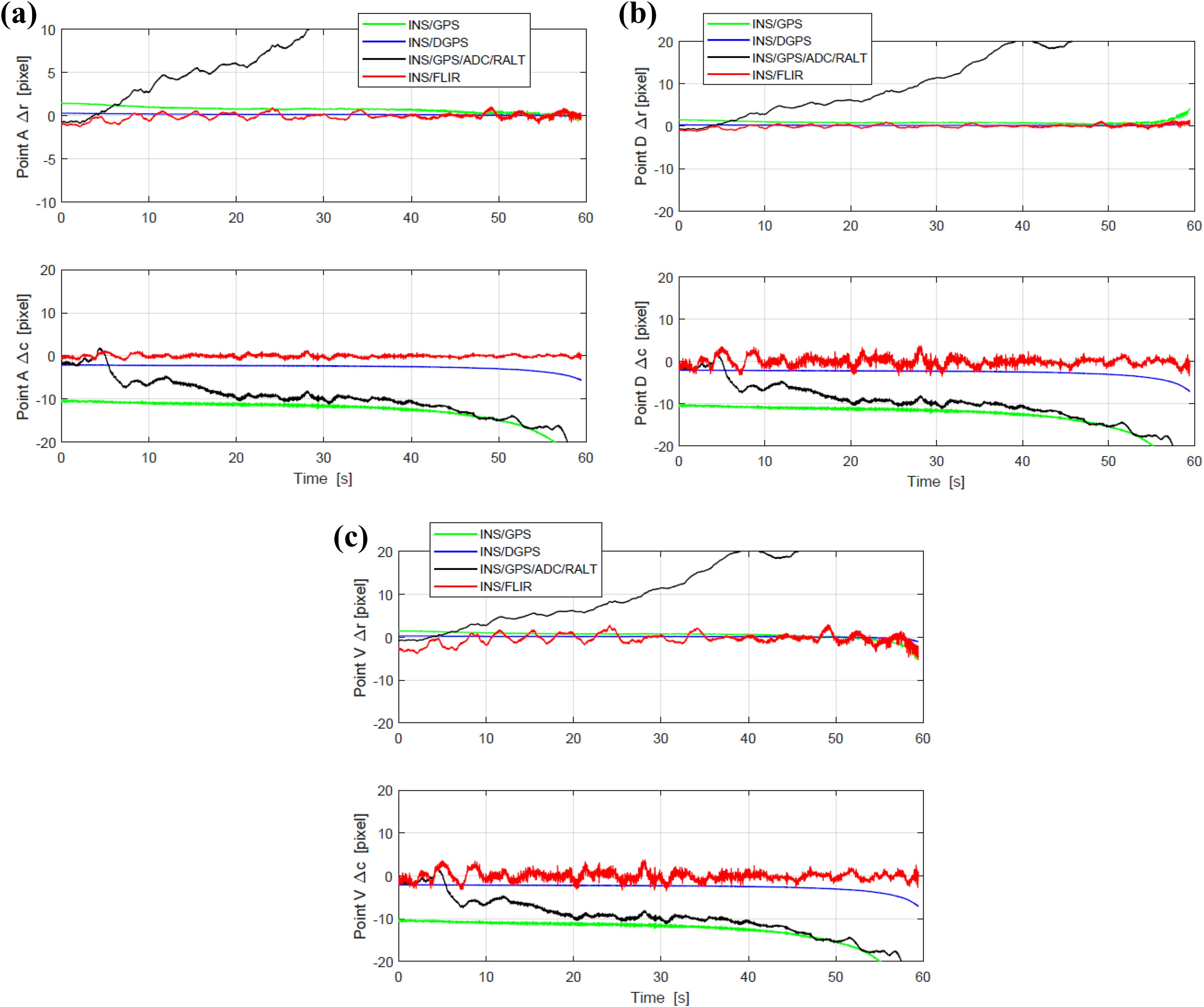
Pixel errors of real and synthetic image registration. (a) row/column pixel bias of point A; (b) row/column pixel bias of point D; and (c) row/column pixel bias of point V.
In addition, the RMSEs of pixel-level registration of point A, D, and V are listed in Table 3. The registration errors (row and column) of INS/GPS/ADC/RALT mode are slightly larger than those of the others, while the registration errors of the proposed algorithm are smaller than those of INS/GPS and INS/GPS/ADC/RALT and even superior to the registration accuracy of INS/DGPS.
RMS pixel registration errors of points A, D, and V.
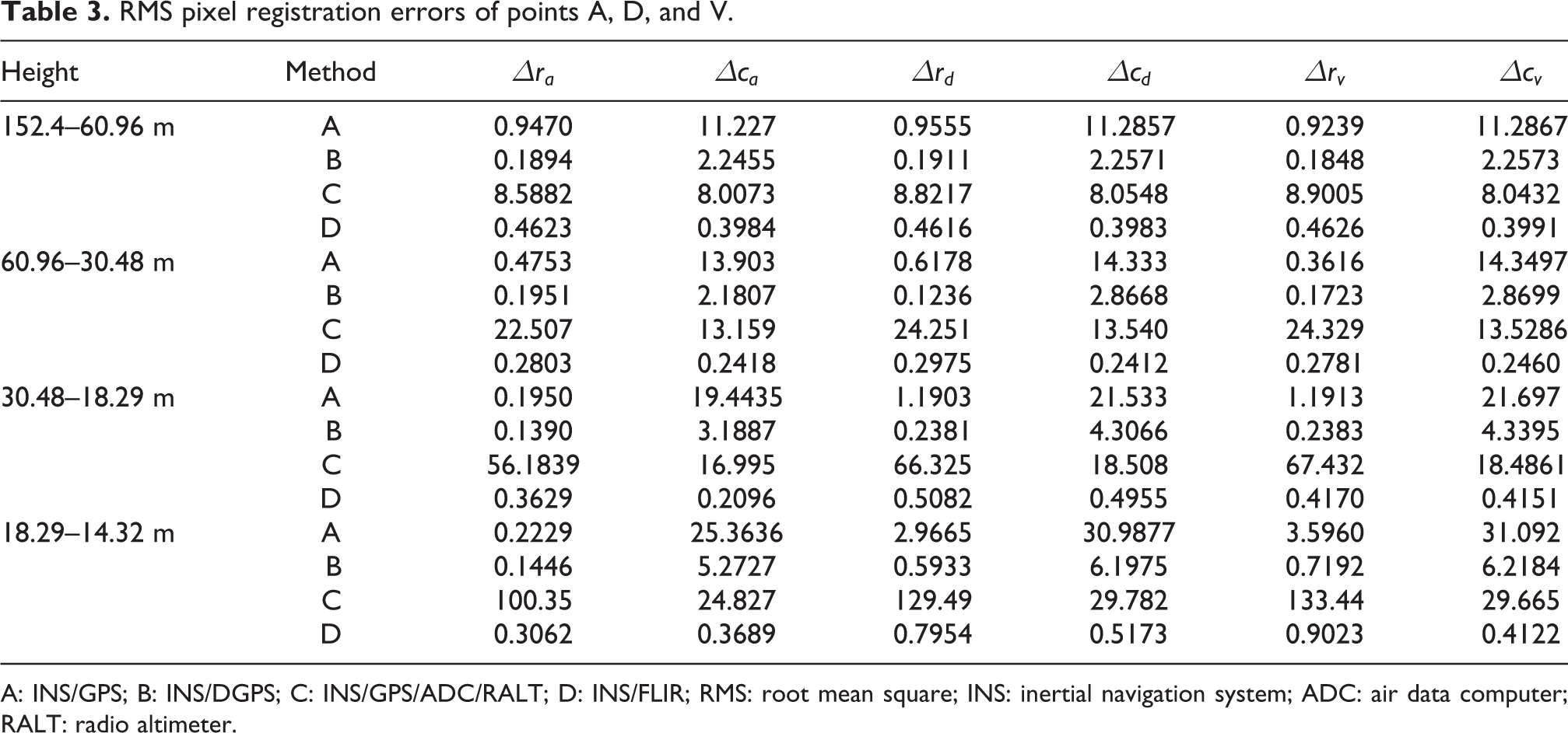
A: INS/GPS; B: INS/DGPS; C: INS/GPS/ADC/RALT; D: INS/FLIR; RMS: root mean square; INS: inertial navigation system; ADC: air data computer; RALT: radio altimeter.
As shown in Figure 12, a prototype of CVS based on embedded computer board (NVIDIA Jetson TX2) is realized. The synthetic 3-D scene is generated by open source 3-D engine (Open Scene Graph, OSG) and is derived by terrain database and the corrected aircraft pose parameters. The flight symbols are designed by electronic instruments development software (ANSYS SCADE Display) and be superimposed on the synthetic scene. The accurate registration between 3-D synthetic scene and 2-D FLIR image is verified by the proposed algorithm. When the application runs on NVIDIA Jetson TX2, the frame rate of CVS is 40–44 Hz. The processing time of each frame is 22.7–25 ms, in which the average time of runway detection is 2 ms, data processing occupied 14–16 ms, and image rendering needs 6–7 ms.
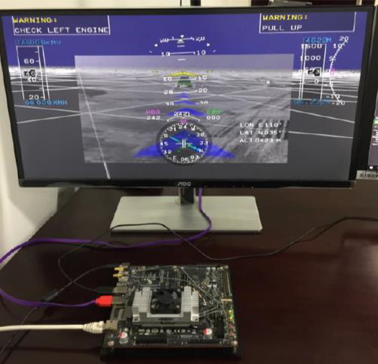
The prototype of CVS based on Jetson TX2. CVS: combined vision system.
Conclusion and future work
In this article, a novel visual–inertial fusion-based registration between real and synthetic images in CVS is proposed. To improve the robustness of CVS, vision observations are established by the three vertices of runway contour extracted from the FLIR images, and the propagation model is formed by the inertial error transfer equation. Through SR-UKF fusion of visual information and inertial data, the errors of inertial measurement can be estimated precisely and the accuracy of pose estimation can be improved. Finally, our proposed method is verified by real flight data. The accurate registration between 3-D synthetic scene and 2-D FLIR image can be achieved. In future works, the authors could use an open-source camera/INS calibration toolbox—ETH Kalibr 42 –44 instead of an electronic total station for calibration.
Footnotes
Declaration of conflicting interests
The author(s) declared no potential conflicts of interest with respect to the research, authorship, and/or publication of this article.
Funding
The author(s) disclosed receipt of the following financial support for the research, authorship, and/or publication of this article: This work was supported by AVIC Technology Innovation Foundation of China (No. 2014D63130R) and Aviation Science Foundation of China (No. 2014ZC31004 and No. 2017ZC31008).