
Abstract
The inverse dynamic model of a three-revolute–prismatic–spherical parallel robot based on Lagrange method is presented. This parallel robot presents a different configuration in the orientation of the actuators of the already reported in the literature. The dynamic model is validated by simulations obtained with a virtual prototype under MSC Automatic Dynamic Analysis of Mechanical Systems environment. For positioning the moving platform in a desired orientation, a proportional–integral–derivative-type controller is implemented for trajectory tracking using the dynamic of the actuators. In this dynamic, the load supported is unknown, that is, due to the inclination of the moving platform, the weight is not evenly distributed. Algebraic identification of parameters is implemented in order to know the load and improve the response in the orientation of the moving platform. Some simulations were performed with the virtual prototype in co-simulation environment under MSC Automatic Dynamic Analysis of Mechanical Systems/View and MATLAB/Simulink to verify the performance of the proportional–integral–derivative controller using the algebraic parameters identification.
Introduction
Parallel robots are defined as a closed kinematic chain mechanism based on two platforms, a fixed and a moving, the latter also known as end effector or moving platform. The end effector is connected to the base through independent kinematic chains, which tend to be symmetrical and through different types of joints, such as prismatic, rotational, universal, and spherical. 1 According to their structure, parallel robots present certain advantages such as rigid structure, high precision, low inertia, and high speeds and accelerations, which have allowed them to be introduced in applications such as motion simulators, three-dimensional printers, rehabilitation systems, medical surgeries, positioning of objects, among others. 2 –8 However, parallel robots also present certain disadvantages such as limitation in the workspace, complexity in the analysis and design of the robot, difficulty in obtaining kinematic and dynamic models because they are highly nonlinear and complex, as well as the singularities that they present due to their configuration. 9 –12
Control in parallel robots is complex; according to Zubizarreta et al., 13 the best control approaches require dynamic models that are difficult to determine and may require significant computational effort that makes it difficult to implement in real time. To achieve a desired control response, the most advanced control methods only consider active joints; as a consequence, the movement of the other joints of the mechanism must be estimated by the kinematic model. This results in the end position of the effector being based on the precision of the model and the parameters identification. Verdeş et al. proposed a parallel robot with two degrees of rotation and one degree of translation. The authors use a set control, that is to say, they use as inputs of the algorithm the difference of the angles calculated by means of the equations of inverse kinematics and the value of the sensors. 14
Chiacchio et al. mention that independent joint controllers (of proportional-derivative (PD) or proportional–integral–derivative (PID) type) are usually employed in industrial robot manipulators but cannot achieve satisfactory performance due to their inherent low rejection to disturbances and parameter variations. 15
Based on the information given above, it was decided to use a method of parameters identification. The algebraic identification methodology requires a rather precise knowledge of the model of the plant; on the other hand, the algebraic identification method is model based and aimed at obtaining an exact, static, formula for the unknown parameters. The parameter calculation formula are obtained via specific algebraic manipulations carried out on the model equations. The operations carried out in algebraic manipulations to eliminate the influence of initial conditions and, also, the so-called classical perturbations (step inputs, ramps, etc.). 16
The design of the three-revolute–prismatic–spherical (3-RPS) parallel robot presented in this article aims to assist in the landing (landing on deck of helicopters on ships). To achieve the objective, the design considers three degrees of freedom (DOF): one translational movement and two rotational movements to keep the platform in horizontal position while the ship is moving. The purpose is to keep the moving platform in a horizontal position, despite the movement of the ship due to the sea waves, in order to make the landing easier and safer, thus avoiding material risks and human losses. The article is divided into five sections. The first section presents the introduction to the work. The second and third sections describe the design of the parallel robot, the kinematic and dynamic models, the control as well as the parameters identification. Subsequently, the fourth section shows the simulation results of the mathematical models and the virtual prototype. Finally, the last section presents the conclusions.
System description
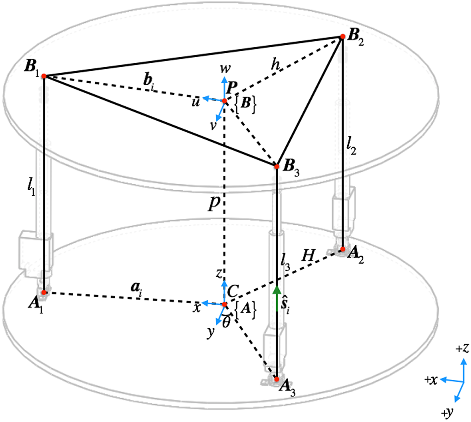
An RPS parallel robot of three DOFs was designed 17 (see Figure 1). The prismatic joints are considered to be actively actuated. As shown in Figure 2, two of the actuators (l 2 and l 3) are in the opposite position with respect to the x-axis, which means that the axes of revolute joints are parallel; however, the third actuator is oriented at 90°, that is, the axis of the revolute joint rotates with respect to the axis y. The 3-RPS parallel robots, proposed by other authors, have the actuators oriented to the center. 18 –23 However, there is a similar robot proposed by Li et al., 24 which consists of a base and a moving platform connected by two identical revolute–prismatic–universal limbs and one spherical–prismatic–revolute limb.

Configuration of the 3-RPS parallel robot. 3-RPS: three-revolute–prismatic–spherical.
Geometric model of the 3-RPS robot. 3-RPS: three-revolute–prismatic–spherical.
Mathematical model
Inverse kinematic
The design of the geometric model of the 3-RPS parallel robot is presented in Figure 2. Revolute joints on the fixed base platform and spherical joints on the moving platform are denoted by
The kinematic parameters can be defined as

In the inverse kinematics, the lengths of the actuator li must be determined as a variable function of the orientation of α and β angles. The lengths li for each actuator can be calculated by the following relations

where li
is length of the ith actuated link,
The vector

According to Figure 2, the geometry of the parallel robot can be expressed as
The lengths of the actuator li can be calculated by the following equation

Finally, the inverse kinematic equations are given by

Numerical simulations were performed using the following design parameters of the parallel robot:
Forward kinematic
The forward kinematics of the parallel robot consist in finding the orientation of the moving platform given the lengths of the actuators

Determination of the 3-RPS structure angles. 3-RPS: three-revolute–prismatic–spherical.
The mathematical model of forward kinematics (7) was reported by Ruiz Hidalgo et al., 25 which is given by a nonlinear system of three equations

To solve the nonlinear forward kinematic equation (7), the Newton–Kantorovich method was implemented. Then proceeded to obtain the α and β angles according to Figure 4.

Angles geometrical representation.
Considering Figure 4(a), the midpoint (8) of the distance between points B 2 and B 3 was determined, later the distance d 1 (9) was calculated, to finally obtain what would be the angle α (10)


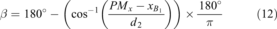
The midpoint (8) of the distance between the points B 2 and B 3 was obtained, and the distance d 2 (11) was later calculated, to finally obtain what would be the angle β (12) (Figure 4(b))
Parallel robot dynamic
To position the moving platform of the robot parallel in the angle α, the displacements of the actuators l 2 and l 3 must move in opposite direction, while the actuator l 1 must remain static (Figure 5(a)). On the other hand, to generate movement with respect to the angle β, l 2 and l 3 are displaced toward the same direction and l 1 moves in the opposite direction (Figure 5(b)).

(a) Moving platform oriented to an angle α and (b) angle β.
To determine the mathematical modeling, three assumptions are considered: (1) forces of the actuators act vertically, derived that the angles
The dynamic equations of the 3-RPS parallel robot are obtained by applying the Euler–Lagrange equation

where α, β, and z represent the movements of the moving platform;
The kinetic energy of the moving platform is given by

where

The potential energy is given by

The mathematical model of the moving platform is given by the set of highly nonlinear differential equation (17). To obtain these equations, kinetic energy (14) and potential energy (16) were substituted in the Lagrangian equation (13), which is given by L = K − V; later the model was derived to obtain the solution

It can be seen that the mathematical model is highly nonlinear, with coupled terms and multivariable. Although the parallel robot is 3-DOF and there are three force inputs (fully actuated system), for controlling α or β angles, two or three actuators are required, which indicates that in these coordinates the system is overactuated.
The Lagrangian motion equations of the parallel robot (17) can be represented in the standard form

where
In addition,
Algebraic parameters identification
Niu et al. 26 conclude that some control strategies developed for controlling the movement of the parallel manipulator require that the manipulator parameters and the load must be known in advance and many of the control techniques, such as PID and fuzzy logic controllers, do not give satisfactory results in the presence of the parameters uncertainties and the unmodeled dynamic in the movement tracking of the manipulators. For this reason, it is proposed to implement a methodology for identifying the mass that each actuator should load to control the moving platform. Next, the procedure for applying the algebraic identification is shown.
The mathematical model for each actuator, considering that the mass of the moving platform and the load it will support (helicopter, passengers, load, etc.) mi , is described by the following ordinary differential equation

where Fi is the force provided by the actuator and bi is a viscous damping. Applying the Laplace transform

Deriving twice with respect to s

Multiplying by s 2 and applying the inverse Laplace transform

Clearing m (mass) is given by

Expressed of the following form
Control
For the mathematical model of the actuator, it is considered to provide the force Fi that should move a mass mi at a distance zi . In this analysis, viscous damping bi and a constant perturbation Pi are considered. The disturbance represents part of the weight that each actuator of the parallel robot must support, which is unknown.
The mathematical model can be obtained by applying Newton’s second law, which is given by

where the subscript
Next, the following PID-type controller is proposed for the desired position trajectory tracking of the moving platform
By replacing equation (26) in equation (25), it results
The use of this controller produces the following closed-loop dynamic for the path-tracking error given by

Taking the first derivative with respect to time

The controller gain

The PID-type controller is a decentralized uncoordinated control strategy relying on the measured error between the desired and the actual position of the actuator hinge.
The desired position trajectory is given by the following Bézier polynomial

where

The parameters of the polynomial are
Figure 6 shows the control diagram implemented in the virtual prototype. It can be seen in the diagram that the input is the desired position, in this case, the angles α and β and the displacement along the z-axis. Subsequently, the actuator lengths are obtained through the inverse kinematics and are used to define the desired trajectories (Bézier polynomial). Finally, the desired position and speed are compared with the real ones so that the PID-type controller is calculated, in order to send the control signal (control force) to the virtual prototype.

PID-type controller diagram with the virtual prototype. PID: proportional–integral–derivative.
Simulation results
Virtual prototype and PID-type controller
Some simulations were carried out with the virtual prototype of the parallel robot in the MD Automatic Dynamic Analysis of Mechanical Systems (ADAMS) software to verify the performance of the PID controller (see Figures 7 and 8).
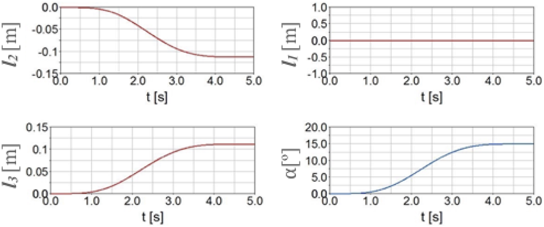
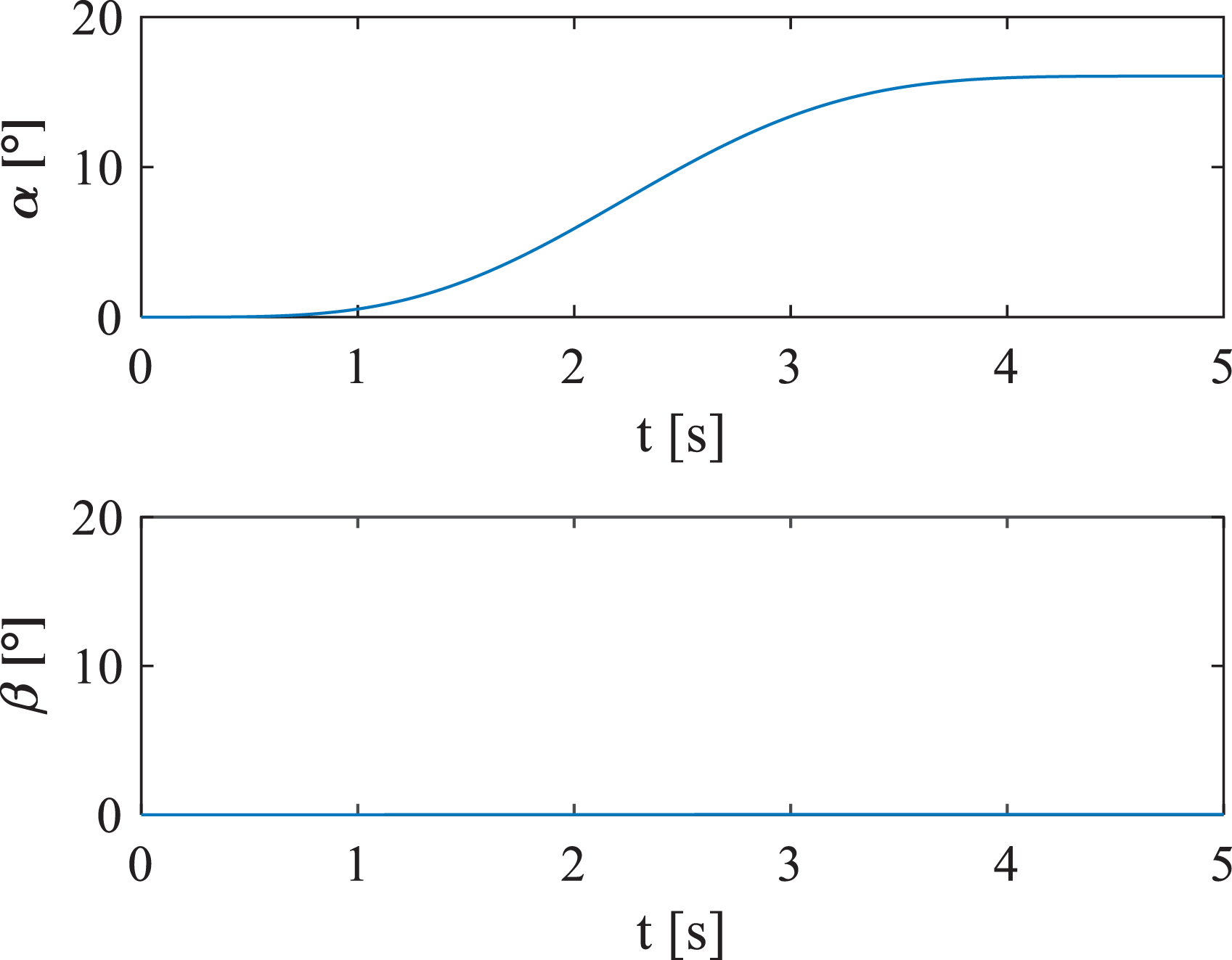
Simulation results for the α = 15° and displacements in actuators.
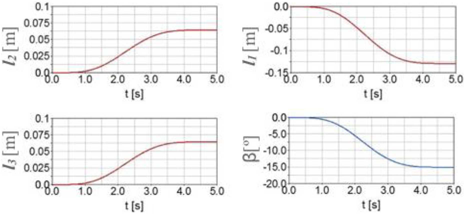
Simulation results for the β = −15° and displacements in actuators.
In Figure 7, angular response of α is shown. The moving platform rotates around the x-axis (Figure 5(a)); this movement is obtained only by the displacement of the actuators 2 (l
2) and 3 (l
3) in the opposite direction. It can be seen that the displacements of the actuators are smooth to get the orientation of the moving platform (
Figure 8 shows the angular response of β. It can be seen that a smooth trajectory from 0° to 15° is obtained on the moving platform. For this movement, displacements of 0.0648 m are required in l 2 and l 3 and −0.1291 m for l 1 (see Figure 8).
Dynamic model with prototype virtual simulations
Figure 9 shows the diagram of the dynamic model implemented in Simulink with the PID-type controller. The simulation results shown in Figures 10 and 11 are similar to Figure 7.

PID-type controller diagram with the mathematical model. PID: proportional–integral–derivative.
Response for
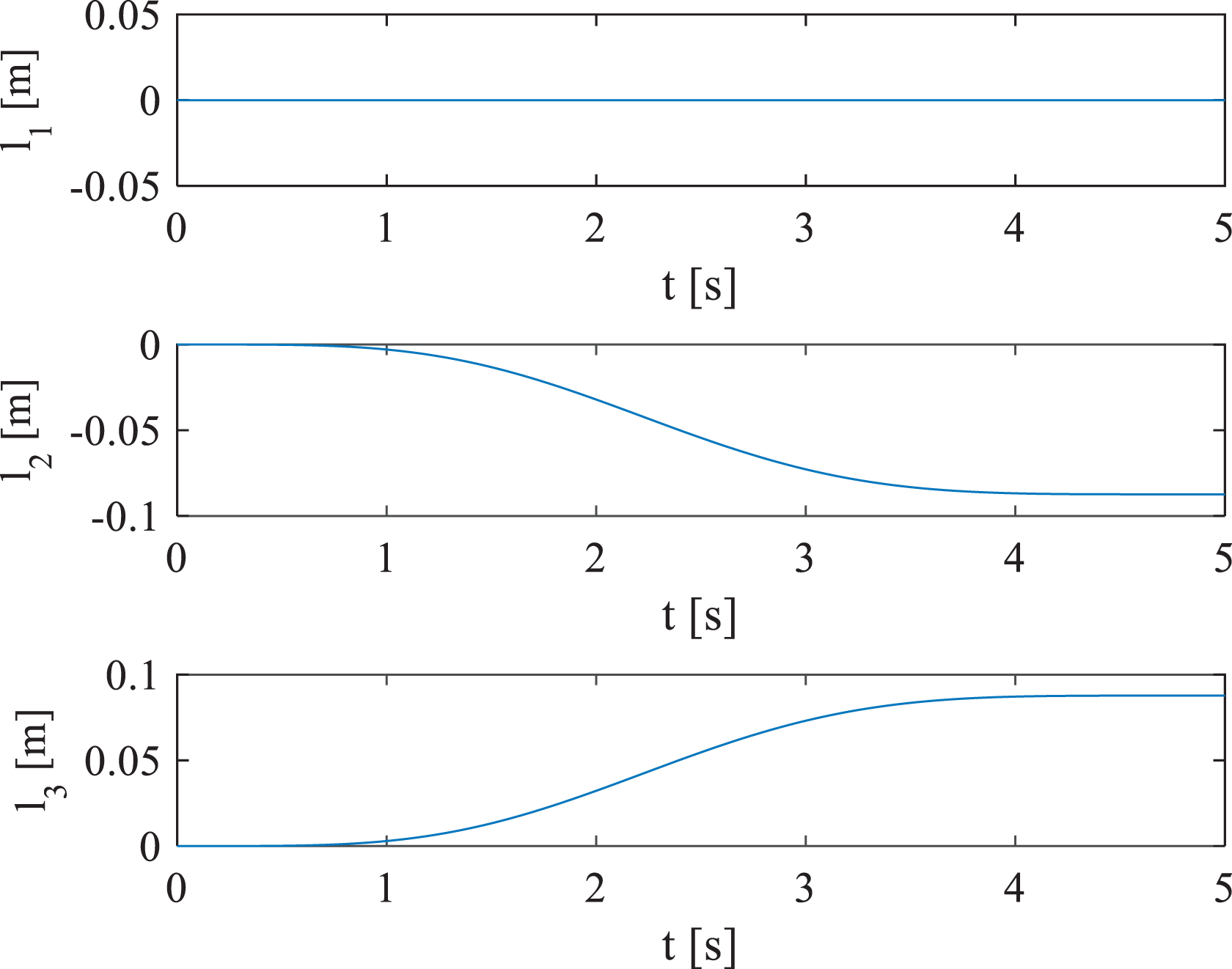
Response of the displacements of actuators for
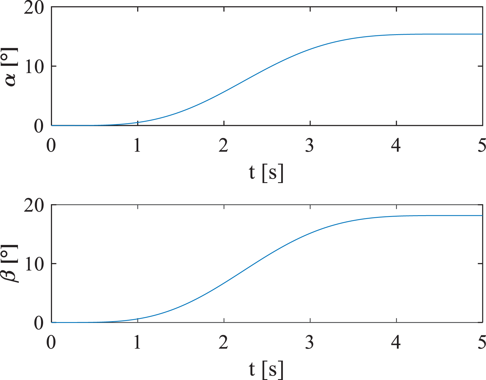
The response to position the moving platform at an angle of
The response of the moving platform for

Response for a desired angle of

Displacements of actuators for
In Figure 14, the response of the moving platform for
Response for a desired angle of
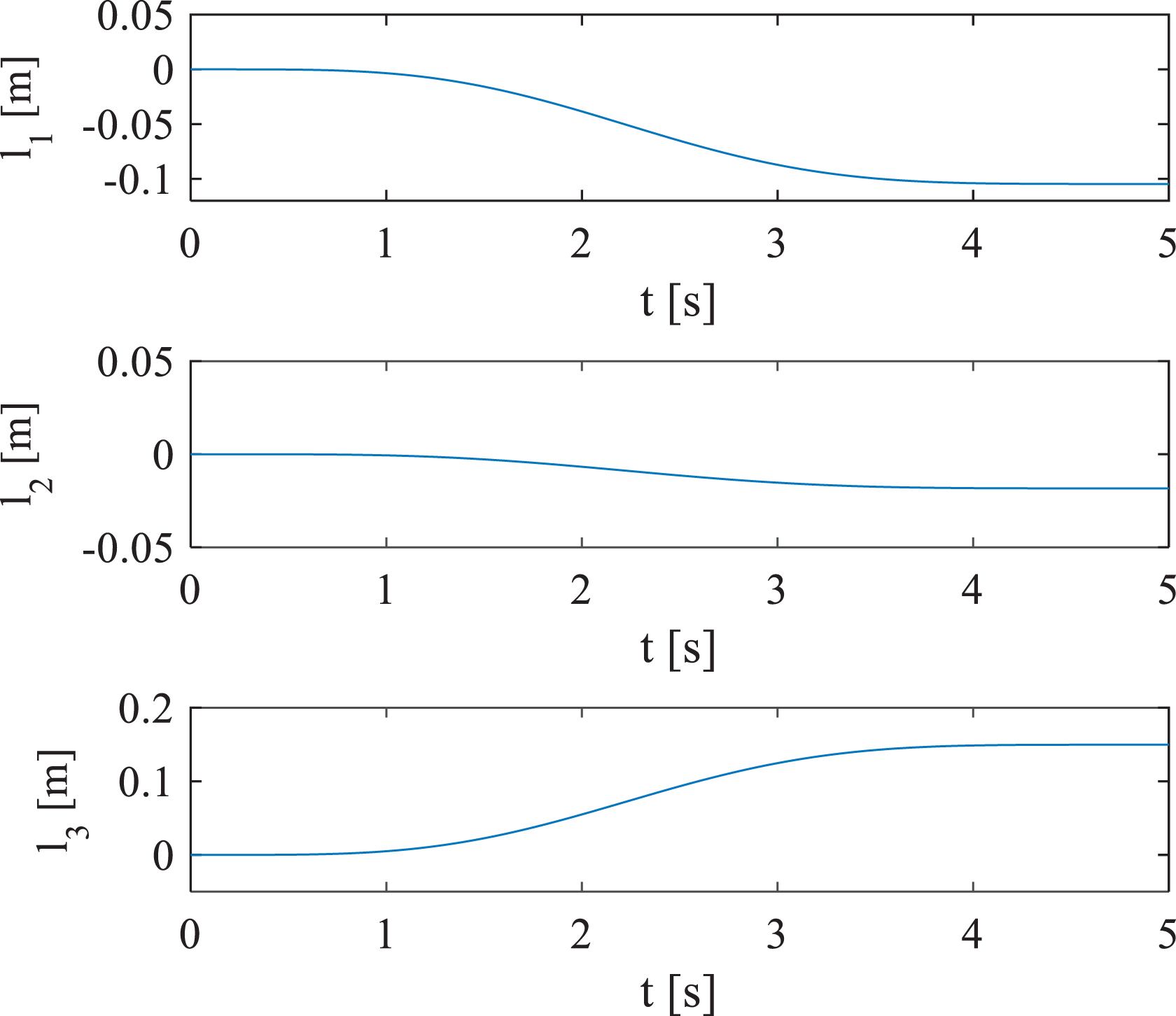
Displacements of actuators for
Figure 16 shows the simulation results for
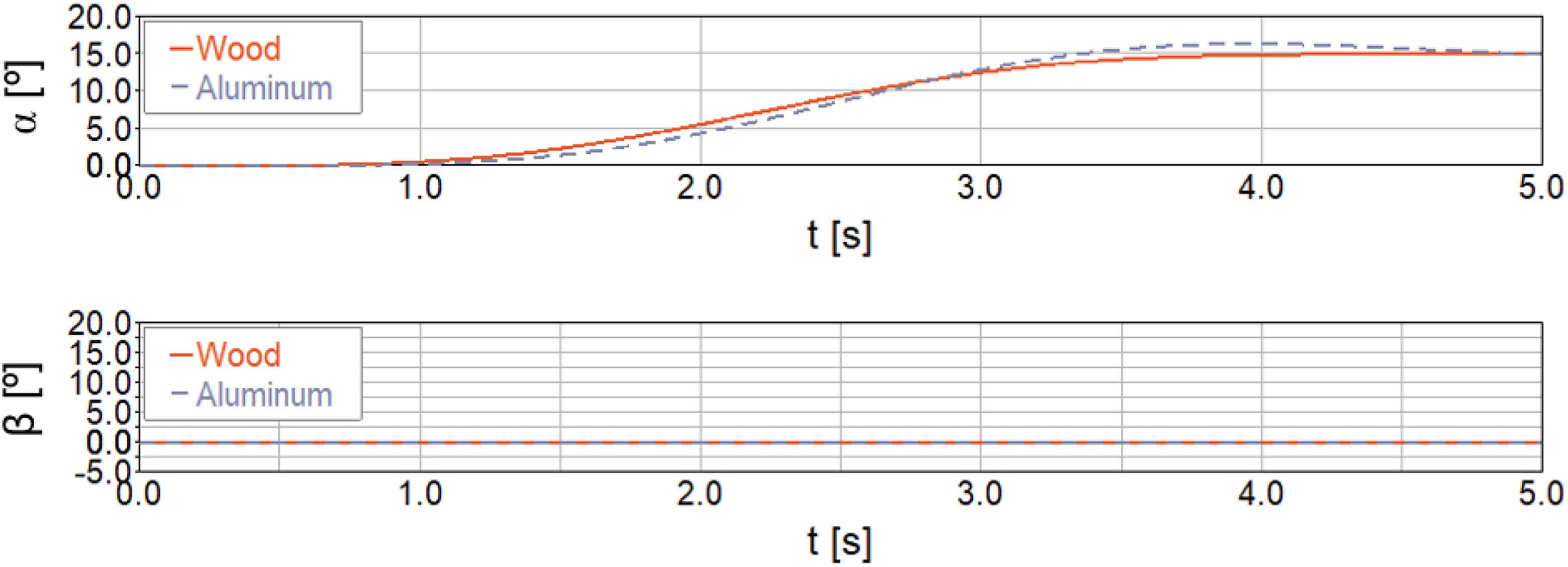
Angles moving platform for material of wood and aluminum.
In Figure 17, the displacements of the actuators
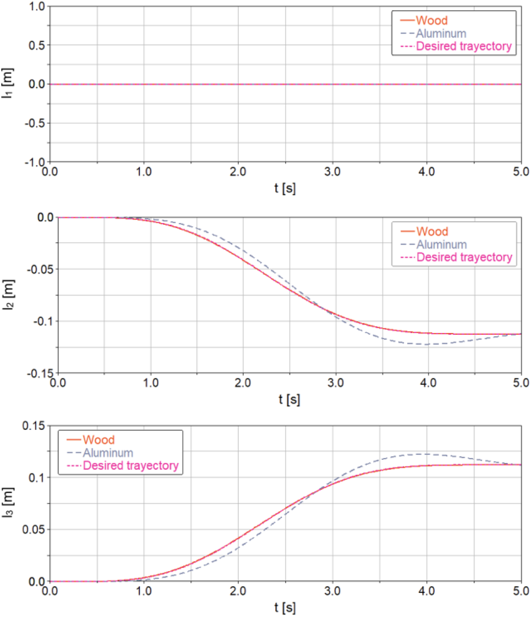
Displacements of actuators for the moving platform of wood and aluminum.
Figure 18 shows the simulation results for

α and β angles in the moving platform made of wood and aluminum.
Figure 19 shows the displacements of the actuators

Displacements of actuators (
Algebraic parameters identification simulation
According to Figures 16 to 19, it was observed that the controller does not follow the trajectory because of parametric uncertainty. Therefore, the algebraic identification was implemented to feedback the controller and, in this way, if any load is placed on the moving platform, the controller will have the correct value of mass. Through the algebraic identification, the values of the (mass) used in the control of the actuators were obtained (Figure 20).

Distribution of the moving platform mass in the three actuators.
Simulation results of the parameters identification were performed in co-simulation with ADAMS and Simulink.
The moving platform mass is 9 kg (wood material), in the controller of each actuator was placed a mass of 3.0802 kg. Therefore, the force obtained from the controller is shown in Figure 21.

Response of actuators
The mass values that were placed in the identifier as initial value were
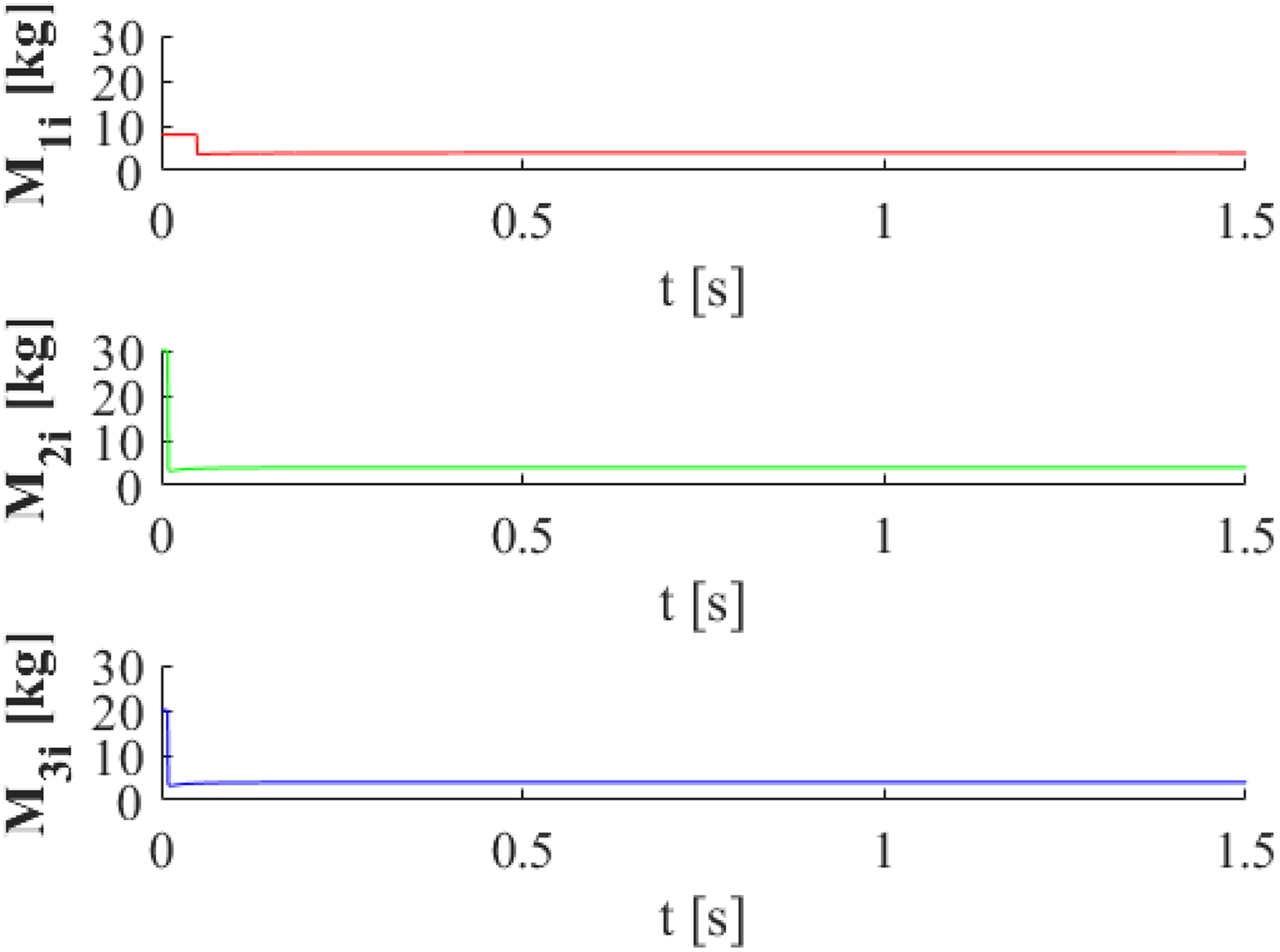
Mass algebraic identification of actuators (wood material).
The displacement of the actuators is shown in Figure 23; since the angles α and β are equal to zero, the displacement was only carried out on the z-axis.

Displacement response of actuators
In Figure 24, the response of the algebraic identification can be appreciated; in this case, the material of the platform was changed by aluminum, moving platform weight is 56.0994 kg. Here it is clear how the mass parameter identification is quickly performed and it is almost exact with respect to the real parameter in the virtual prototype.

Mass algebraic identification of actuators (aluminum material).
The response of the control force (26) and the corresponding displacement of the actuators are shown in Figures 25 and 26, respectively. The angles α and β are equal to zero, because the moving platform displacement was only carried out on the z-axis.

Response of actuators

Displacement response of actuators
As can be observed in the simulations with the algebraic identification (Figures 21 to 26), the controller responds appropriately since it is able to estimate the mass of the platform. It is important to mention that these simulations were done by moving the platform over the z-axis, in order to corroborate that the algebraic identification is working properly. However, if the platform changes position, that is, the actuators move differently, the mass will vary in each actuator, but the identifier will estimate the mass according to the position of the platform.
A scale prototype is being constructed to validate the kinematics, dynamics, and control strategies, in which the Max Jac Thomson Linear Actuators MX24-B8M30E1 were selected based on the results presented in this article.
Conclusion
This article presents a 3-RPS parallel robot, which has the characteristic of having two actuators directed to the same axis and not to the center as the known 3-RPS robots and a third actuator directed to the center of the platform. A PID-type controller is proposed for positioning the moving platform in a desired orientation, which is based on determining the lengths of the actuators considering the kinematic model and thus achieve the position desired on the moving platform of the parallel robot. The simulation results obtained from the virtual prototype in MSC ADAMS, the kinematic and dynamic models show a good approximation, and the position of the moving platform is controlled. Coupled with this, the implementation of parameters identification helped to improve the response of the controller. Without this data, it is not possible to obtain the desired response if the weight of the moving platform is modified.
Footnotes
Declaration of conflicting interests
The author(s) declared no potential conflicts of interest with respect to the research, authorship, and/or publication of this article.
Funding
The author(s) disclosed receipt of the following financial support for the research, authorship, and/or publication of this article: This work was supported by grants of the Tecnológico Nacional de México through Fortalecimiento a Cuerpos Académicos with the project “Diseño y construcción de un robot paralelo para el anaveaje”, IDCA 24320, CENIDET-CA-16.